RIDGID 760 FXP Power Drive Manuel utilisateur
- Catégorie
- Outils électroportatifs
- Taper
- Manuel utilisateur

760 FXP Power Drive
• Français– 17
• Castellano – 35
• Deutsche – 55
Power Drive
Manual

999-995-242.10_REV A
ii
760 FXP Power Drive
Table of Contents
Safety Symbols ............................................................................................................................................................. 2
General Power Tool Safety Warnings*
Work Area Safety ....................................................................................................................................................... 2
Electrical Safety ......................................................................................................................................................... 2
Personal Safety .......................................................................................................................................................... 3
Power Tool Use And Care ........................................................................................................................................... 3
Battery Tool Use And Care ......................................................................................................................................... 3
Service ....................................................................................................................................................................... 4
Specific Safety Information ......................................................................................................................................... 4
Power Drive Safety ..................................................................................................................................................... 4
RIDGID® Contact Information ...................................................................................................................................... 5
Description .................................................................................................................................................................... 5
Specifications ............................................................................................................................................................... 6
Standard Equipment ................................................................................................................................................... 7
Pre-Operation Inspection ............................................................................................................................................. 7
Set-Up and Operation
Installing Die Heads ................................................................................................................................................... 8
Resisting Threading Forces ...................................................................................................................................... 10
Installing/Removing Battery .......................................................................................................................................11
Threading ..................................................................................................................................................................11
Inspecting Threads ................................................................................................................................................... 12
RIDGID Link App Connection (Wireless Communication) ...................................................................................... 13
760 FXP Power drive – other uses ............................................................................................................................ 13
Storage ........................................................................................................................................................................ 14
Maintenance Instructions .......................................................................................................................................... 14
Cleaning ................................................................................................................................................................... 14
Changing Dies in Die Heads .................................................................................................................................... 14
Troubleshooting ........................................................................................................................................................ 15
Service And Repair .................................................................................................................................................. 16
Threading Oil .............................................................................................................................................................. 16
Optional Equipment ................................................................................................................................................... 16
Disposal ....................................................................................................................................................................... 16
Electromagnetic Compatibility (EMC) ...................................................................................................................... 16
FCC/ICES Statement ......................................................................................................................... Inside Back Cover
EC Declaration ................................................................................................................................... Inside Back Cover
Lifetime Warranty ..........................................................................................................................................Back Cover
*Original Instructions - English

760 FXP Power Drive
Power Drive
WARNING!
Read this Operator’s Manual
carefully before using this
tool. Failure to understand
and follow the contents of this
manual may result in electrical
shock, fire and/or serious per-
sonal injury
760 FXP Power Drive
Record Serial Number below and retain product serial number which is located on nameplate.
Serial
No.

999-995-242.10_REV A
2
760 FXP Power Drive
General Power Tool Safety
Warnings*
WARNING
Read all safety warnings, instructions, illustra-
tions and specifications provided with this power
tool. Failure to follow all instructions listed below
may result in electric shock, fire and/or serious
injury.
SAVE ALL WARNINGS AND INSTRUCTIONS
FOR FUTURE REFERENCE!
The term “power tool” in the warnings refers to your
mains-operated (corded) power tool or battery-operated
(cordless) power tool.
Work Area Safety
• Keep work area clean and well lit. Cluttered or dark
areas invite accidents.
• Do not operate power tools in explosive atmo-
spheres, such as in the presence of flammable liq-
uids, gases or dust. Power tools create sparks which
may ignite the dust or fumes.
• Keep children and bystanders away while operating
a power tool. Distractions can cause you to lose con-
trol.
Electrical Safety
• Power tool plugs must match the outlet. Never mo-
dify the plug in any way. Do not use any adapter
plugs with earthed (grounded) power tools. Un-
modified plugs and matching outlets will reduce risk of
electric shock.
• Avoid body contact with earthed or grounded sur-
faces, such as pipes, radiators, ranges and refrig-
erators. There is an increased risk of electric shock if
your body is earthed or grounded.
• Do not expose power tools to rain or wet condi-
tions. Water entering a power tool will increase the
risk of electric shock.
• Do not abuse the cord. Never use the cord for car-
rying, pulling or unplugging the power tool. Keep
cord away from heat, oil, sharp edges or moving
parts. Damaged or entangled cords increase the risk
of electric shock.
• When operating a power tool outdoors, use an
extension cord suitable for outdoor use. Use of a
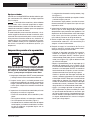
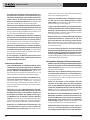
Safety Symbols
In this operator’s manual and on the product, safety symbols and signal words are used to communicate important safety
information. This section is provided to improve understanding of these signal words and symbols.
This is the safety alert symbol. It is used to alert you to potential personal injury hazards. Obey all safety messages that follow
this symbol to avoid possible injury or death.
DANGER indicates a hazardous situation which, if not avoided, will result in death or serious injury.
WARNING indicates a hazardous situation which, if not avoided, could result in death or serious injury.
CAUTION indicates a hazardous situation which, if not avoided, could result in minor or moderate injury.
NOTICE indicates information that relates to the protection of property.
This symbol means read the operator’s manual carefully
before using the equipment. The operator’s manual
contains important information on the safe and proper
operation of the equipment.
This symbol means always wear safety glasses with
side shields or goggles when handling or using this
equipment to reduce the risk of eye injury.
This symbol indicates the risk of fingers, hands, clothes
and other objects catching on or between gears or other
rotating parts and causing crushing injuries.
This symbol indicates the risk of electrical shock.
NOTICE
DANGER
WARNING
CAUTION
This symbol indicates the risk of machine tipping, caus-
ing striking or crushing injuries.
This symbol means do not wear gloves while operating
this machine to reduce the risk of entanglement.
This symbol means use support device to resist the
threading forces, improve control, and reduce the risk of
striking, crushing, and/or other injuries.
This symbol indicates that the marked equipment ex-
ceeds 55 lbs. (25kg). Exercise caution when lifting or
moving to reduce the risk of injury.
* The text used in the general power tool safety warnings section of this manual is verbatim, as required, from the applicable UL/CSA/EN 62841-1 standard. This
section contains general safety practices for many different types of power tools. Not every precaution applies to every tool, and some do not apply to this tool.

999-995-242.10_REV A 3
760 FXP Power Drive
3
cord suitable for outdoor use reduces the risk of electric
shock.
• If operating a power tool in a damp location is un-
avoidable, use a Ground Fault Circuit Interrupter
(GFCI) protected supply. Use of a GFCI reduces the
risk of electric shock.
• If operating a power tool in a damp location is
unavoidable, use a Residual Current Device (RCD)
protected supply. Use of a RCD reduces the risk of
electric shock.
• It is recommended that the tool always be supplied
via a Residual Current Device having a residual
current of 30mA or less.
Personal Safety
• Stay alert, watch what you are doing and use com-
mon sense when operating a power tool. Do not
use a power tool while you are tired or under the in-
fluence of drugs, alcohol or medication. A moment
of inattention while operating power tools may result in
serious personal injury.
• Use personal protective equipment. Always wear
eye protection. Protective equipment such as dust
mask, non-skid safety shoes, hard hat, or hearing
protection used for appropriate conditions will reduce
personal injuries.
• Prevent unintentional starting. Ensure the switch
is in the OFF-position before connecting to power
source and/or battery pack, picking up or carrying
the tool. Carrying power tools with your finger on the
switch or energizing power tools that have the switch
ON invites accidents.
• Remove any adjusting key or wrench before turn-
ing the power tool ON. A wrench or a key left attached
to a rotating part of the power tool may result in per-
sonal injury.
• Do not overreach. Keep proper footing and balance
at all times. This enables better control of the power
tool in unexpected situations.
• Dress properly. Do not wear loose clothing or jew-
elry. Keep your hair, clothing and gloves away from
moving parts. Loose clothes, jewelry or long hair can
be caught in moving parts.
• If devices are provided for the connection of dust
extraction and collection facilities, ensure these
are connected and properly used. Use of dust col-
lection can reduce dust-related hazards.
• Do not let familiarity gained from frequent use of
tools allow you to become complacent and ignore
tool safety principles. A careless action can cause
severe injury within a fraction of a second.
Power Tool Use And Care
• Do not force the power tool. Use the correct power
tool for your application. The correct power tool will
do the job better and safer at the rate for which it was
designed.
• Do not use the power tool if the switch does not
turn it ON and OFF. Any power tool that cannot be
controlled with the switch is dangerous and must be
repaired.
• Disconnect the plug from the power source and/
or remove the battery pack, if detachable, from
the power tool before making any adjustments,
changing accessories, or storing power tools.
Such preventive safety measures reduce the risk of
starting the power tool accidentally.
• Store idle power tools out of the reach of children
and do not allow persons unfamiliar with the
power tool or these instructions to operate the
power tool. Power tools are dangerous in the hands
of untrained users.
• Maintain power tools and accessories. Check for
misalignment or binding of moving parts, break-
age of parts and any other condition that may
affect the power tool’s operation. If damaged, have
the power tool repaired before use. Many accidents
are caused by poorly maintained power tools.
• Keep cutting tools sharp and clean. Properly main-
tained cutting tools with sharp cutting edges are less
likely to bind and are easier to control.
• Use the power tool, accessories and tool bits etc.
in accordance with these instructions, taking into
account the working conditions and the work to
be performed. Use of the power tool for operations
different from those intended could result in a hazard-
ous situation.
• Keep handles and grasping surfaces dry, clean
and free from oil and grease. Slippery handles and
grasping surfaces do not allow for safe handling and
control of the tool in unexpected situations.
Battery Tool Use And Care
• Recharge only with the charger specified by the
manufacturer. A charger that is suitable for one type
of battery pack may create a risk of fire when used with
another battery pack.
• Use power tools only with specifically designated

999-995-242.10_REV A
4
760 FXP Power Drive
Power Drive Safety
• Always use the support device provided with the
tool. Loss of control during operation can result in per-
sonal injury.
• Keep sleeves and jackets buttoned while operat-
ing the tool. Do not reach across the tool or pipe.
Clothing can be caught by the pipe or the tool resulting
in entanglement.
• Only one person must control the work process
and tool operation. Additional people involved in the
process may result in unintended operation and per-
sonal injury.
• Keep floors dry and free of slippery materials such
as oil. Slippery floors invite accidents.
• Do not wear gloves while operating the tool. Do not
reach across the tool or pipe. Gloves can be caught
by the pipe or the tool resulting in entanglement.
• Always firmly hold the power drive when threading
or backing die head off the pipe to resist threading
forces, regardless of support device use. This will
reduce the risk of striking, crushing and other injuries.
• Follow instructions on proper use of this machine.
Do not use for other purposes such as drilling
holes or turning winches. Other uses or modifying
this machine for other applications may increase the
risk of serious injury.
• Do not use this power drive if ON/OFF switch is
broken. This switch is a safety device that lets you shut
off the motor by releasing the switch.
• Do not use dull or damaged dies. Sharp cutting tools
require less torque and the power drive is easier to
control.
• Keep handles dry and clean, free from oil and
grease. Allows for better control of tool.
• Only use RIDGID die heads with RIDGID 760 FXP
Power Drive. Other die heads may not fit correctly in
the power drive increasing the risk of equipment dam-
age and personal injury.
• Before operating a RIDGID® Power Drive, read and
understand:
– This operator’s manual
– The battery/charger manual
– The instructions for any other equipment or material
used with this tool
Failure to follow all instructions and warnings may
result in property damage and/or serious injury.
battery packs. Use of any other battery packs may
create a risk of injury and fire.
• When battery pack is not in use, keep it away from
other metal objects, like paper clips, coins, keys,
nails, screws or other small metal objects that can
make a connection from one terminal to another.
Shorting the battery terminals together may cause
burns or a fire.
• Under abusive conditions, liquid may be ejected
from the battery; avoid contact. If contact acci-
dentally occurs, flush with water. If liquid contacts
eyes, additionally seek medical help. Liquid ejected
from the battery may cause irritation or burns.
• Do not use a battery pack or tool that is damaged
or modified. Damaged or modified batteries may ex-
hibit unpredictable behavior resulting in fire, explosion
or risk of injury.
• Do not expose a battery pack or tool to fire or ex-
cessive temperature. Exposure to fire or temperature
above 265 °F (130 °C) may cause explosion.
• Follow all charging instructions and do not charge
the battery pack or tool outside the temperature
range specified in the instructions. Charging im-
properly or at temperatures outside the specified
range may damage the battery and increase the risk
of fire.
Service
• Have your power tool serviced by a qualified repair
person using only identical replacement parts.
This will ensure that the safety of the power tool is
maintained.
• Never service damaged battery packs. Service of
battery packs should only be performed by the manu-
facturer or authorized service providers.
Specific Safety Information
WARNING
This section contains important safety information
that is specific to this tool. Read these precautions
carefully before using the RIDGID 760 FXP Power
Drive to reduce the risk of electrical shock or other
serious injury.
SAVE ALL WARNINGS AND INSTRUCTIONS
FOR FUTURE REFERENCE!
Keep this manual with the machine for use by the oper-
ator.

999-995-242.10_REV A 5
760 FXP Power Drive
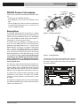
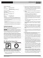
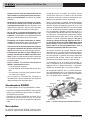
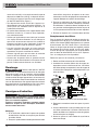
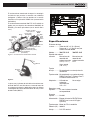
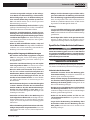
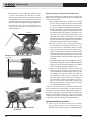
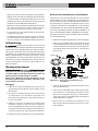
Figure 1 – 760 FXP Power Drive
Figure 2 – 692 Support Arm
The 760 FXP Power Drive serial number plate is located
on the battery rail under the handle. The last 4 digits of
the serial number indicate the month and year of the
manufacture (MMYY).
Figure 3 – Machine Serial Number
RIDGID Contact Information
If you have any question concerning this RIDGID® prod-
uct:
– Contact your local RIDGID distributor.
– Visit RIDGID.com to find your local RIDGID contact
point.
– Contact Ridge Tool Technical Service De part ment
at rtctechservices@emer son.com, or in the U.S. and
Canada call (800) 519-3456.
Description
The RIDGID® Model 760 FXP Power Drive is a battery
powered tool which provides power for threading pipe and
conduit. Forward and Reverse rotation can be selected
with a Forward/Reverse Slide Switch while ON/OFF is
controlled by a momentary contact switch.
The power drive uses RIDGID 11-R (Model 760 FXP
11-R) and 12-R (Model 760 FXP 12-R) die heads (de-
pending on tool configuration) for 1/8" – 2" pipe. For the
Model 760 FXP 11-R version, an adapter is required for
1/8" – 1¼" sizes. This adapter and the 1½" – 2" sizes for
11-R, as well as all 12-R die heads in the Model 760 FXP
12-R, are held in the Power Drive using a Quick-acting
Retaining Mechanism. Other die heads such as OO-R
may be used with adapters. Due to the threading speed
exceeding 40 rpm, RIDGID High Speed dies and Nu-
Clear™, Endura-Clear™ or Extreme Performance™
Thread Cutting Oil are recommended for use with the
760 FXP Power Drive.
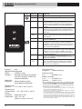
The Tool Status Lights indicate information related to wire-
less connection status, nearing the end of proper thread
creation, battery status, and tool error status. The work
lights surrounding the die head area turn on when the
ON/OFF switch is depressed to illuminate the work area.
The power drive includes wireless technology to allow
connection to smart phones and tablets. See “RIDGID
Link App connection (Wireless Communication)” section
for details.
The 760 FXP 12-R power drive can also be used to power
the RIDGID 258/258XL Pipe Cutters and for other appli-
cations, (See “Other Uses”).
5
Handle
Push Pad
LED Work
Light
Drive
Pawls
Reset
Pawl
Gear
Housing
Motor
Housing
Battery
Serial
Plate
ON/OFF
Switch
Battery
Latch
Handle Tool Status
Lights
Forward/Reverse
Slide Switch
Warning
Label
Handle
Jaws
Drive
Ring
XXXXXXXXXMMYY

999-995-242.10_REV A
6
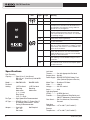
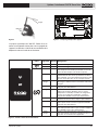
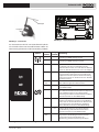
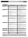
760 FXP Power Drive
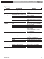
Icon Blinking Solid Meaning
Light Light
Blue Connection to RIDGID Link app possible.
Blue Connection to RIDGID Link app established.
Green Nearing the end of thread for 1/2" - 2" NPT. User
should pay closer attention to the die head area as
the completion of the thread is nearing. LED work
light will also vary in brightness.
Yellow Battery charge is low and only limited number of
threads remain before battery must be recharged
(can only thread about 3 2” threads or 4-5 1” threads
on remaining charge).
Yellow Battery low and tool will not operate. Recharge
Red battery/insert fully charged battery.
Yellow Maintenance is required. Consult RIDGID Link app
for more information.
Red Tool has stopped due to an event exceeding usable
limits (e.g. current, temperature, or stability). Confirm
proper set-up and restart use. Consult RIDGID Link
app for more information.
Red Tool has malfunctioned and will not operate. Remove
battery and allow tool to rest, then reinsert battery.
If light still ON, have tool serviced. Consult RIDGID
Link app for more information.
Purple Firmware update in process, tool cannot be used
while updating. Consult RIDGID Link app for more
information.
Purple Firmware update was interrupted and not completed,
Red tool cannot be used. Continue and complete update
per app instructions.
Left Hand
Threads ............ Yes with Appropriate Die Head
Support Arm ..... No. 692
Power Supply ... RIDGID RB-FXPXX Battery Pack
(See Optional Equipment Section)
Motor Type ....... Brushless DC Motor
Watts ................ 1080 W
Voltage ............. 54V DC nominal
Amps ................ 20 A
Operating Speed
(RPM) ............... 42 RPM, No load
Controls ............ Forward/Reverse Slide Switch and
ON/OFF Momentary Contact Switch
Gear Head ....... Die Cast Aluminum, Permanently
Greased
Operating
Temperature ..... -4°F to 140°F (-20°C to 60°C)
Storage
Temperature ..... -4°F to 140°F (-20°C to 60°C)
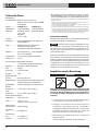
Specifications
Pipe Threading
Capacity ........... Pipe 1/8" to 2" (3 to 50 mm)
Bolt 1/4" to 1" (6 to 25 mm) with 00-RB
Die Head
Model ............... 760 FXP 11-R 760 FXP 12-R
Die Head
Holding 11-R Die Head 12-R Die Head
Retaining Retaining
Mechanism Mechanism
(1 ½ – 2 inch)
Ring Spring
(1/8 – 1 ¼ inch)
Die Type ........... High Speed Dies Recommended#
Oil Type .............RIDGID Nu-Clear™, Endura-Clear™
or Extreme Performance™ Thread
Cutting Oil Recommended#
Adapter ..............Used with Not Required
1/8" - 1¼"
Die Heads
Figure 4 – Tool Status Lights

999-995-242.10_REV A 7
760 FXP Power Drive
Wireless Connection
Range ............... 33 ft. (10 m) Max.
Dimensions ...... 27.8" x 5.2" x 9.1"
(706 mm x 132 mm x 231 mm)
Weight (no battery/
attachment) ...... 24.0 lb (10.9 kg)
Sound Pressure
(LPA)* ................. 82.6 dB(A), K=3
Sound Power
(LWA)* ................ 91.1 dB(A), K=3
Vibration* .......... <2.5m/s², K=1.5
# Use of Alloy dies or improper oil types (including RIDGID Dark™) may re-
sult in reduced die life, poor thread quality, or reduced tool performance.
* Sound and Vibration measurements are measured in accordance with a stand-
ardized test per Standard EN 62481-1.
- Vibration levels may be used for comparison with other tools and for preliminary
assessment of exposure.
- Sound and vibration emissions may vary due to your location and specific use
of these tools.
- Daily exposure levels for sound and vibration need to be evaluated for each
application and appropriate safety measures taken when needed. Evaluation of
exposure levels should consider the time a tool is switched off and not in use.
This may significantly reduce the exposure level over the total working period.
Standard Equipment
Refer to the RIDGID catalog for details on equipment sup-
plied with specific machine catalog numbers.
Selection of appropriate materials and instal-
lation, joining and forming methods is the responsibility of
the system designer and/or installer. Selection of improper
materials and methods could cause system failure.
Stainless steel and other corrosion resistant materials can
be contaminated during installation, joining and forming.
This contamination could cause corrosion and premature
failure. Careful evaluation of materials and methods for
the specific service conditions, including chemical and
temperature, should be completed before any installation
is attempted.
Pre-Operation Inspection
WARNING
Before each use, inspect 760 FXP Power Drive and
correct any problems to reduce the risk of serious
injury from electric shock, crushing injuries and
other causes and prevent power drive damage.
1. Make sure the ON/OFF switch is released and re-
move battery from tool.
2. Clean any oil, grease or dirt from the power drive and
support device, including the handles and controls.
This aids inspection and helps prevent the machine
or control from slipping from your grip.
3. Inspect the power drive and support arm for the fol-
lowing:
• Proper assembly, maintenance and completeness.
• Damaged, misaligned or binding parts.
• Proper operation of switches (Figure 1).
•
Support arm gripping teeth are clean and in good
condition. Teeth can be cleaned with a wire brush.
•
Presence and readability of the warning label (Fi-
gure 1).
•
Any other condition which may prevent safe and
normal operation.
If any problems are found, do not use the power
drive or support device until the problems have been
repaired.
4. Inspect the cutting edges of the dies for wear, de-
formation, chips or other issues. Dull or damaged
cutting tools increase the amount of force required,
produce poor quality threads and increase the risk of
injury.
5. Inspect and maintain any other equipment being
used per its instructions to make sure it is functioning
properly.
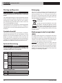
6. Following the Set Up and Operation instructions,
check the power drive for proper operation.
•
Move the Forward/Reverse slide switch to the
Forward position. Depress and release the ON/
OFF switch. Confirm that the power drive rotates in
correct direction (see Figure 5A) and stops when
releasing the switch.
•
Repeat the process for the Reverse operation (see
Figure 5B). If the power drive does not rotate in
the correct direction, or the ON/OFF switch does
not control the machine operation, do not use the
machine until it has been repaired.
Change position of the Forward/Reverse Slide
Switch only when the ON/OFF switch is released.
Allow the power drive to come to a complete stop
before reversing the direction with the Forward/
Reverse Slide Switch. This will reduce the risk of
power drive damage.
•
Depress and hold the ON/OFF switch. Inspect the
moving parts for misalignment, binding, odd noises
or any other unusual conditions. Release the ON/
OFF switch. If any unusual conditions are found, do
not use the machine until it has been repaired.
7
NOTICE

999-995-242.10_REV A
8
760 FXP Power Drive
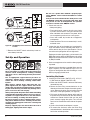
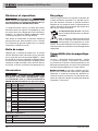
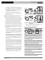
Figure 5A – FORWARD (Clockwise) Switch Position
Figure 5B – REVERSE (Counter-Clockwise) Switch
Position
7. Release the ON/OFF switch and with dry hands re-
move battery from tool.
Set-Up and Operation
WARNING
Set up and operate the power drive according to
these procedures to reduce the risk of injury from
electric shock, entanglement, striking, crushing
and other causes, and to help prevent power drive
damage.
Use an appropriate support device per these in-
structions. Support devices improve control and
reduce the risk of striking, crushing, and/or other
injuries.
When using a support device other than the sup-
plied support arm, the support device must react
against the gear housing. Support devices contact-
ing the motor housing or handle may damage these
parts or increase the risk of injury.
Always firmly hold the power drive when threading
or backing die head off the pipe to resist use forces,
regardless of support device use. This will reduce
the risk of striking, crushing and other injuries.
Do not wear gloves or loose clothing. Keep sleeves
and jackets buttoned. Loose clothing can become
entangled in rotating parts and cause crushing and
striking injuries.
Properly support pipe. This will reduce the risk of
falling pipe, tipping and serious injury.
Do not use a power drive without a properly oper-
ating ON/OFF switch and Forward/Reverse Slide
Switch.
One person must control both the work process and
the ON/OFF switch. Do not operate with more than
one person. In case of entanglement, the operator
must be in control of the ON/OFF switch.
1. Check work area for:
• Adequate lighting.
• Flammable liquids, vapors or dust that may ignite.
If present, do not work in area until sources have
been identified and corrected. The power drives
are not explosion proof and can cause sparks.
• Clear, level, stable, dry location for all equipment
and operator.
• Good ventilation. Do not use extensively in small,
enclosed areas.
2. Inspect the pipe to be threaded and associated fit-
tings and confirm that the selected power drive is a
correct tool for the job. See Specifications. Do not
use to thread anything other than straight stock.
Equipment for other applications can be found in the
Ridge Tool catalog, online at RIDGID.com or by calling
Ridge Tool Technical Service in the U.S. and Canada
at (800) 519-3456.
3. Make sure equipment to be used has been properly
inspected.
4. Properly prepare the pipe as needed. Make sure the
pipe is squarely cut and deburred. Pipe cut at an
angle can damage the dies while threading or cause
difficulty engaging the die head.
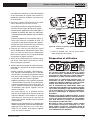
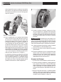
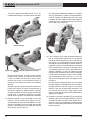
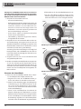
Installing Die Heads
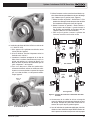
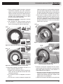
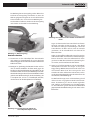
5. Installing 12-R Die Heads (760 FXP 12-R), 11-R (1½"
- 2") Die Heads or Adapter (760 FXP 11-R):
a. Make sure ON/OFF switch is released and battery
removed from tool.
b. Rotate the Drive Ring counterclockwise in the
direction of the arrows to open the retaining mech-
anism. Release the drive ring and confirm that the
drive stays in the open position (see Figure 6).
c. Fully insert the die head or adapter spline end into
the power drive to automatically lock the retaining
mechanism. Rotate the die head until the drive
pawls securely engage the spline. The 12-R die
head can be inserted from either side of the power
drive.
d. Confirm that the die head/adapter is secure.
e. To remove the die head, rotate the Drive Ring
counterclockwise in the direction of the arrows and
hold in the unlocked position.

999-995-242.10_REV A 9
760 FXP Power Drive
9
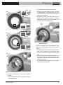
Figure 6A – Retaining Mechanism (760 FXP 12-R)
Figure 6B – Retaining Mechanism (760 FXP 11-R)
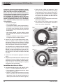
Figure 7 – Installing Adapter
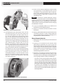
6. Installing 11-R Die Heads, 1¼" and smaller (760 FXP
11-R only):
a. Make sure ON/OFF switch is released and battery
removed from tool.
b. If needed install the adapter, refer to step 5.
c. Squarely insert the octagonal end of the die head
into the power drive until secured by the spring
ring. The die heads can only be inserted from the
adapter side of the tool.
d. To remove, pull die head from power drive. If
needed, use a soft face hammer or a block of
wood to tap the die head out. Do not pound on the
die head, this can damage the tool.
Figure 8 – Installing 11/4" or Smaller 11-R Die Heads
(760 FXP 11-R only)
7. Position the power drive Forward/Reverse Slide
Switch for the desired right or left hand thread. See
Figure 9.
a. Move the Slide Switch to the Forward rotation po-
sition. This will produce right-hand threads when
the die is inserted from the left (front) side of the
tool.
b. Move the Slide Switch to Reverse position. This
will produce right-hand threads when the die is
inserted from the right (back) side of the tool (for
760 FXP 12-R only).
c. For left-hand threads, reverse the Forward/Re-
verse Slide Switch positions.
Spring
Ring
OPEN
CLOSED
OPENED
CLOSED
OPENED
OPEN
OPEN

999-995-242.10_REV A
10
760 FXP Power Drive
Figure 9 – Forward/Reverse Slide Switch/Die Head
Orientation
8. Make sure that pipe to be threaded is stable and se-
cured to prevent tipping during use. Use appropriate
pipe stands to support pipe length.
9. If using the 418 Oiler, check the level of RIDGID
Thread Cutting Oil. Remove the chip tray and confirm
that the filter screen is clean and fully submerged in
oil. Replace or add oil if necessary. Place the 418
Oiler bucket under the pipe end to be threaded.
If using Aerosol Oil, check the threading oil quantity
in cans. Make sure that there is enough oil for thread-
ing operation.
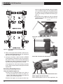
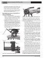
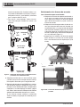
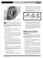
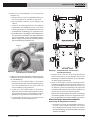
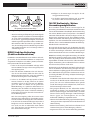
Resisting Threading Forces
Using the supplied support arm:
a. Always use the supplied support arm unless it
can’t be used because of space or other con-
straints. The support arm clamps to the pipe and
helps to resist the threading forces.
b. Position the support arm on pipe, so end of sup-
port arm aligns with end of pipe and top of support
arm is horizontal (Figure 10). This properly places
the support arm for threading and prevents thread-
ing oil from entering the Power Drive Housing (Fi-
gure 11).
c. Make sure that the support arm jaws are squarely
aligned with the pipe and securely tighten the sup-
port arm handle.
Figure 10A – Positioning the Support Arm
Figure 10B – Positioning the Support Arm
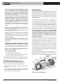
Figure 11 – Proper Orientation of the 760 FXP Power Drive
When support arm can’t be used:
When threading pipe in place or similar application, the
Support
Arm
Horizontal
Aligned
Support
Arm
FORWARD
FORWARDREVERSE
REVERSE

999-995-242.10_REV A 11
760 FXP Power Drive
support arm may not be able to be used because of
space constraints.
a. If possible, remove the pipe and thread in a vise.
If this cannot be done, other support devices must
be used to help resist threading forces, such as
placing the power drive gear housing or alumi-
num body against an adjacent structural member
(examples include walls, beams and joists). This
requires that the pipe and surroundings be able to
withstand the weight of the tool and the threading
forces. It may be necessary to add temporary or
permanent pipe supports or structural elements.
b. For right hand threads, die head will rotate clock-
wise (looking at the face of the Die Head). Forces
developed by the threading torque will be in the op-
posite or counter-clockwise direction. Rotation and
force will be reversed for left hand threads. Make
sure that the support device is set up to properly
absorb the threading force.
c. Do not place the power drive handle, plastic body,
or battery against adjacent structural members to
react threading forces, as this may cause power
drive damage.
d. Keep power drive against the structural member
and do not place fingers or hands between the
power drive and the structural member. When
backing die head off thread, always firmly hold
the power drive to resist forces from breaking the
thread chips. These steps will reduce the risk of
striking, crushing and other injuries. The ON/OFF
switch can be released at any time to shut OFF the
power drive.
Always firmly hold the power drive when threading or
backing die head off pipe to resist forces, regardless of
support device use. This will reduce the risk of striking,
crushing and other injuries. The ON/OFF switch can be
released at any time to shut off the power drive.
Installing/Removing Battery
10. With dry hands, insert a fully charged battery into the
power drive. The Tool Status Lights will illuminate. See
Figure 4.
The tool has a latch to securely grip the battery. The
latch will engage with a sound when the battery is
inserted. Confirm by lightly pulling on the battery and
ensure that it does not separate from the tool.
To remove the battery, depress the latch and slide the
battery out of the tool.
Figure 12 – Battery Latch
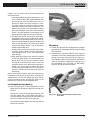
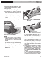
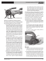
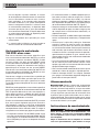
Threading
11. Position the die head over the pipe end and support
the power drive as directed in the Resisting Threading
Forces Section.
12. Simultaneously actuate the ON/OFF switch and push
against the Push Pad or die head cover plate with the
palm of free hand to start the thread (see Figure 13).
The LED Work Light will illuminate when the ON/OFF
switch is pressed. For applications requiring use of
the 11-R Adapter (for 1/8" through 1¼" Die Heads),
only push on the die head cover plate.
Figure 13A – Starting the Thread Using the Die Head
Cover Plate
Latch

999-995-242.10_REV A
12
760 FXP Power Drive
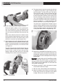
Figure 13B – Starting the Thread Using the Push Pad
Do not wear gloves, jewelry or use a rag while push-
ing– this increases the risk of entanglement and
injury. Once the dies engage the pipe, threads will be
cut as the dies pull themselves onto the end of the
pipe.
Always firmly hold the power drive handle to resist
the handle forces. Support devices can slip and allow
the power drive to move. The ON/OFF switch can be
released at any time to shut off the power drive.
13. Stop pushing on push pad or die head cover plate and
apply a generous quantity of RIDGID Thread Cutting
Oil to the area being threaded. This will lower threading
torque, improve thread quality and increase die life
(see Figure 14).
The power drive will stop if the tool rotates quickly, ex-
ceeding a predetermined angle. If the tool is stopped
for this reason, remove the tool from the pipe,
properly support the power drive per the Resisting
Threading Forces section and continue operation.
Figure 14 – Threading Pipe
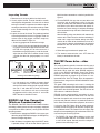
14. The power drive will alert the user when the die head
is approaching the end of a typical thread for most
pipe sizes/types. The lower LED of the Tool Status
Lights will blink green, and the LED work light will
vary intensity to indicate that the user has threaded
for about 8-9 rotations based on size and signals that
the user should pay closer attention to the die head
area as the completion of the thread is nearing; this is
not meant to indicate that the thread is complete. This
feature is useable on 1/2" - 2" NPT threads only; LED
will not illuminate for smaller threads. See Figure 4.
The power drive is equipped with LED Work Lights to
improve visibility to the die head area while threading.
Depress the ON/OFF switch until the end of the pipe
is even with edge of the dies and release the switch.
Let the power drive come to a complete stop. The
Figure 15 – Pipe Even with Edge of Dies
15. Reverse the Forward/Reverse Slide Switch and actu-
ate the ON/OFF switch to remove Die Head from the
threaded pipe. Hold onto the power drive handle firmly
to resist the handle forces developed while backing off
the Die Head.
Change position of the Forward/Reverse Slide
Switch only when the ON/OFF switch is released. Allow
the power drive to come to a complete stop before revers-
ing the direction with the Slide Switch. This will reduce the
risk of power drive damage.
16. Release the ON/OFF switch and remove the power
drive with Die Head from the pipe.
17. With dry hands, remove battery from the power drive.
18. Wipe oil and debris off the threads and out of the die
head, taking care not to cut yourself on sharp debris
or edges. Clean up any oil spills in the work area.
NOTICE

999-995-242.10_REV A 13
760 FXP Power Drive
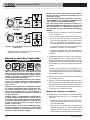
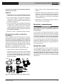
Inspecting Threads
1. Remove any oil, chips or debris from the thread.
2. Visually inspect thread. Threads should be smooth
and complete, with good form. If issues such as thread
tearing, thin threads, or pipe out-of-roundness are ob-
served, the thread may not seal when made up. Refer
to the Troubleshooting chart for help in diagnosing
these issues.
3. Inspect the size of the thread. The preferred method
of checking thread size is with a ring gauge. There are
various styles of ring gauges, and their usage may
differ from that shown in Figure 16.
• Screw ring gauge onto the thread hand tight.
• Look at how far the pipe end extends through the
ring gage. The end of the pipe should be flush with
the side of the gauge plus or minus one turn. If
thread does not gauge properly, cut off the thread,
adjust the die head and cut another thread. Using
a thread that does not gauge properly can cause
leaks.
Figure 16 – Checking Thread Size
• If a ring gauge is not available to inspect thread
size, it is possible to use a new clean fitting repre-
sentative of those used on the job to gauge thread
size. For 2" and under NPT threads, the threads
should be cut to obtain 4 to 5 turns to hand tight
engagement with the fitting and for 2" and under
BSPT threads it should be 3 turns.
RIDGID Link App Connection
(Wireless Communication)
The RIDGID® 760 FXP Power Drive includes wireless
technology allowing communication to properly equipped
smart-phones or tablets (“devices”) running iOS or Android
operating systems.
1. Download the appropriate RIDGID® Link app to your
device by going to RIDGID.com/apps, the Google Play
Store or the Apple App Store.
2. After the battery is installed or after the ON/OFF switch
is pressed, the top LED of the Tool Status Lights will
blink blue when connection to a device is possible. See
Figure 4.
3. Find the RIDGID Link app icon on your device and
launch the app by selecting the icon. Via the app,
search for nearby tools and select the desired RIDGID
tool. Refer to your device instructions for specific in-
formation on how to connect via wireless technology.
Once connected, the top LED of the Tool Status Lights
will be lit blue.
After the initial pairing, most devices will automatically
connect to the Tools when the wireless technology is
active and in range and if device settings are config-
ured to do so. Power drive should be less than 33 ft.
(10 m) from the device to be detected. Any obstacle
between the tool and device can reduce the opera-
tional range.
4. Follow the app instructions for proper use.
5. The wireless communication turns OFF when the
battery is removed from the tool.
760 FXP Power drive – other
uses
This manual contains specific instructions for the use of
the 760 FXP Power Drive to thread with various RIDGID
die heads. When used with other RIDGID equipment
(such as the RIDGID 258/258XL Power Pipe Cutter)
follow the instructions and warnings supplied with that
RIDGID equipment on proper set up and use. It is rec-
ommended that 760 FXP Power Drive be operated in
Reverse when using with the RIDGID 258/258XL Power
Pipe Cutter.
The green LED indicating that the user is nearing the
end of a typical thread may illluminate during use in other
applications but should be ignored. The LED will turn off
after about 3-4 additional rotations.
RIDGID cannot provide specific instructions for every
possible use for the 760 FXP Power Drive. The user must
evaluate the specific work scenario and use good work
practices and methods. If there is any doubt about the use
of this Power Drive for these other purposes, do not use it.
If using the 760 FXP Power Drive for other purposes,
carefully evaluate and prepare for the work using the gen-
eral guidelines below. This Power Drive will supply high
torque and correspondingly high handle forces which can
cause striking and crushing injuries.
• The RIDGID 774 Square Drive Adapter can be used
to adapt the Model 760 FXP 12-R Power Drive to turn
a male 15/16" square. Securely attach the adapter to
prevent it from detaching in use.
Thin Ring
Gauge
Flush
(Basic Size) One Turn Large
(Maximum Size) One Turn Small
(Minimum Size)
Checking Threads With Ring Gauge

999-995-242.10_REV A
14
760 FXP Power Drive
• An appropriate method to withstand all handle forces
must be developed (See “Resisting Threading Forces”
section). Forces could exceed 1000 lbs. (455 kg). Sup-
port devices can be placed against the gear housing of
the 760 FXP Power Drive (Figure 1).
• Always keep the power drive against the support device
– do not place body parts between the power drive and
the support device.
• There should be no relative movement between the
power drive and the support device during use.
• Confirm that the application (such as operating or exer-
cising a valve) is free to turn, not jammed and that the
ends of travel are known. If the system jams or goes
solid during use, handle forces will increase abruptly
and significantly or the power drive may rotate.
• If using to exercise or operate valves or other equip-
ment, follow all equipment manufacturer instructions.
Do not overload the equipment.
• Use such that the power drive reaction force pulls away
from the user.
• Release the ON/OFF switch at any time to shut off the
power drive. Make sure that you are able to release the
ON/OFF switch.
Storage
Remove battery from the 760 FXP Power
Drive. Power Drive and battery must be kept dry and
indoors or well covered if kept outdoors. Avoid storing in
extreme heat or cold. Store the machine in a locked area
that is out of reach of children and people unfamiliar with
Power Drive. This machine can cause serious injury in
the hands of untrained users. Refer to the battery/charger
manual.
Maintenance Instructions
WARNING
Make sure that the ON/OFF switch is released and
battery is removed from tool before performing
maintenance or making any adjustment.
Maintain tool according to these procedures to
reduce the risk of injury from electrical shock, en-
tanglement and other causes.
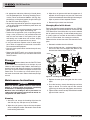
Cleaning
1. After each use, empty the threading chips from the
418 Oiler chip tray and wipe out any oil residue.
2. Wipe off any oil, grease, chips or dirt from the power
drive, including the handles and controls. Clean the die
head retaining mechanism.
WARNING
3. Wipe off any oil, grease or dirt from the support arm. If
required, clean the support arm jaws with a wire brush
and lubricate feedscrew thread with light lubricating oil.
Wipe any excess oil from exposed surfaces.
4. Remove chips and dirt from die heads.
Changing Dies in Die Heads
Due to the threading speed exceeding 40 rpm, RIDGID
High Speed dies are recommended for use with the 760
FXP Power Drive. Use of Alloy dies may result in reduced
die life, poor thread quality, or reduced tool performance.
A variety of dies are available for installation in RIDGID
11-R or 12-R Die Heads. See catalog for availability.
Remove the four screws from cover and remove the cover
plate.
1. Remove the old dies from the die head.
2. Insert new dies into slots – numbered edge up. Num-
bers on the dies must correspond with those on the
die head slots. Always replace dies as a set.
Figure 17 – Installing Dies In Die Head
3. Replace the cover plate and tighten the four screws
lightly.
4. Place die head on already threaded pipe until dies
begin to thread. This forces stop on dies outward
against lugs on cover plate and properly sets the size.
5. Tighten the four screws securely. Remove the threaded
pipe and make a test cut.
Dies
4
Cover
1
Die Head Threaded Pipe
(Throat in Down Position)
Up
Screws
3
AB
4
3
2
2

999-995-242.10_REV A 15
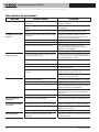
760 FXP Power Drive
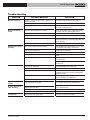
SYMPTOM POSSIBLE REASONS SOLUTION
Machine will not run.
Machine not able to
thread.
Die head does not start
threading.
Torn threads.
Out-of-round or crushed
threads.
Support device turns
while threading.
Thin Threads.
Troubleshooting
Battery is completely discharged or battery is no
longer functional.
Battery not properly inserted into handle of tool.
Tool has reached over temperature threshold.
Die Head Retaining Mechanism Open.
Dull dies.
Overload due to torn or out-of-round threads
Poor quality or insufficient thread cutting oil.
Insufficient voltage.
Die head not square with end of pipe.
Pipe end not squarely cut.
Dull or broken dies.
Machine running in wrong direction.
Dies set improperly in the die head.
Incorrect Die Type Used.
Damaged, chipped or worn out dies.
Improper or insufficient thread cutting oil.
Incorrect type of die for material.
Poor pipe material/quality.
Pipe wall thickness too thin.
Support arm jaws dirty.
Support arm not aligned properly.
Support arm not tight.
Dies not placed in proper order.
Insert fully charged battery/replace battery.
Check to assure battery is fully inserted.
Remove battery and allow tool to cool for 30 min-
utes before reattempting use.
Rotate die head by head to engage drive pawls
into spline and close retaining mechanism.
Replace dies.
See possible reasons below.
Use RIDGID® Nu-Clear™, Endura-Clear™ or
Extreme Performance™ Thread Cutting Oil in ad-
equate quantity.
Check battery charge level and charge battery.
Push against Push Pad (for 12-R or 1½" -2" 11-R)
or cover plate of die head to start thread.
Cut the pipe end squarely.
Replace dies.
Check position of the Forward/Reverse Slide
Switch.
Ensure chasers are set outward against the
cover plate lugs.
Confirm that dies are in the correct position within
the die head.
Use RIDGID High-Speed Dies only.
Replace dies.
Only use RIDGID® Nu-Clear™, Endura-Clear™
or Extreme Performance™ Thread Cutting Oil in
adequate quantity.
Select high-speed, stainless steel , or alloy dies
that are suitable for the application.
Use higher quality pipe.
Use schedule 40 or heavier wall thickness.
Clean with wire brush.
Align support arm squarely with the pipe.
Tighten feedscrew.
Place dies in proper die head slot.

999-995-242.10_REV A
16
760 FXP Power Drive
Service And Repair
WARNING
Improper service or repair can make the 760 FXP
Power Drive unsafe to operate.
The “Maintenance Instructions” will take care of most
of the service needs of this machine. Any problems not
addressed by this section should only be handled by a
RIDGID Authorized Independent Service Center. Use only
RIDGID service parts.
For information on your nearest RIDGID Authorized Inde-
pendent Service Center or any service or repair questions
see Contact Information section in this manual.
Threading Oil
For information concerning RIDGID® Thread Cutting Oil
use and handling, refer to the labels on the container and
Safety Data Sheet (SDS). SDS is available at RIDGID.
com or by contacting Ridge Tool Technical Service
Department at (800) 519-3456 in U.S. and Canada or
rtctechservices@emerson.com.
Optional Equipment
WARNING
To reduce the risk of serious injury, only use acces-
sories specifically designed and recommended for
use with the RIDGID 760 FXP Power Drive, such as
those listed.
Disposal
Parts of these tools contain valuable materials and can be
recycled. There are companies that specialize in recycling
that may be found locally. Dispose of the components in
compliance with all applicable regulations. Contact your
local waste management authority for more information.
For EC Countries: Do not dispose of electri-
cal equipment with household waste!
According to the European Guideline 2012/
19/EU for Waste Electrical and Electronic
Equipment and its implementation into na-
tional legislation, electrical equipment that
is no longer usable must be collected separately and
disposed of in an environmentally correct manner.
Electromagnetic Compatibility
(EMC)
The term electromagnetic compatibility is taken to mean
the capability of the product to function smoothly in an
environment where electromagnetic radiation and elec-
trostatic discharges are present and without causing
electromagnet interference to other equipment.
These tools conform to all applicable EMC
standards. However, the possibility of them causing in-
terference in other devices cannot be precluded. All EMC
related standards that have been tested are called out in
the tool’s technical document.
Catalog
No. Description
70788 RB-FXP40 4.0Ah Li-Ion Battery
70793 RB-FXP80 8.0Ah Li-Ion Battery
Battery and Adapter Packs
NOTICE
Model
No. Catalog
No. Description
760 FXP
12-R
42600 770 Adapter for 00-R (1/8" – 1") and 00-RB (¼" – 1")
42605 771 Adapter for 0-R (1/8" – 1")
42610 772 Adapter for 11-R (1/8" – 1¼")
42615 773 Adapter for 111-R (1/8" – 1¼")
42620 774 Square Drive Adapter -15/16"
760 FXP
11-R 39187 Ratcheting Ring
760 FXP
11-R
and
760 FXP
12-R
45928 692 Support Arm
74463 Carrying Case
10883 418 Oiler with 1 Gallon Nu-Clear Oil
22088 Extreme Performance Aerosol Thread Cutting Oil
16703 425 1/8" – 2½" TRISTAND Vise
36273
460-6 1/8"
–
6" TRISTAND Vise

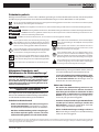
Système d’entraînement
760 FXP Power Drive
Power Drive
AVERTISSEMENT !
Familiarisez-vous avec ce mode
d’emploi avant d’utiliser l’appar-
eil. Tout manque de compréhen-
sion ou d’adhésion aux consignes
ci-après augmenterait les risques
de choc électrique, d’incendie et/
ou de grave blessure corporelle.
Système d’entraînement 760 FXP Power Drive
Inscrivez ci-dessous le numéro de série de l’appareil indiqué sur sa plaque signalétique pour future référence.
No de
série

999-995-242.10_REV A
18
Système d’entraînement 760 FXP Power Drive
Table des matières
Symboles de sécurité ................................................................................................................................................. 19
Consignes générales visant la sécurité des appareils électriques*
Sécurité des lieux ..................................................................................................................................................... 19
Sécurité électrique ................................................................................................................................................... 19
Sécurité individuelle ................................................................................................................................................. 20
Utilisation et entretien des appareils électriques ...................................................................................................... 20
Utilisation et entretien des appareils à piles ............................................................................................................. 21
Service après-vente ................................................................................................................................................. 21
Consignes de sécurité spécifiques ........................................................................................................................... 21
Sécurité du système d’entraînement ........................................................................................................................ 21
Coordonnées RIDGID® ............................................................................................................................................... 22
Description .................................................................................................................................................................. 22
Caractéristiques techniques ...................................................................................................................................... 24
Equipements de base .............................................................................................................................................. 24
Inspection préalable ................................................................................................................................................... 24
Préparation et fonctionnement
Montage des têtes de filière ..................................................................................................................................... 26
Résistance au retour de manivelle de l’appareil ....................................................................................................... 28
Installation et retrait du bloc-piles ............................................................................................................................. 29
L’opération de filetage............................................................................................................................................... 29
Terminaison du filetage ............................................................................................................................................ 29
Inspection du filetage ............................................................................................................................................... 30
Connexion à l’application RIDGID Link (communication sans fil). ........................................................................ 31
Autres utilisations du système d’entraînement 760 FXP Power Drive ................................................................... 31
Remisage ..................................................................................................................................................................... 32
Entretien ...................................................................................................................................................................... 32
Nettoyage ................................................................................................................................................................. 32
Remplacement des filière ......................................................................................................................................... 32
Dépannage ............................................................................................................................................................... 33
Révisions et réparations ........................................................................................................................................... 34
Huile de coupe ............................................................................................................................................................ 34
Accessoires ................................................................................................................................................................ 34
Recyclage .................................................................................................................................................................... 34
Compatibilité électromagnétique (EMC) ................................................................................................................... 35
Déclaration FCC/ICES ..............................................................................................................Recto de page de garde
Déclaration CE ..........................................................................................................................Recto de page de garde
Garantie à vie ...........................................................................................................................................Page de garde
*Traduction du texte d’origine en anglais.
La page est en cours de chargement...
La page est en cours de chargement...
La page est en cours de chargement...
La page est en cours de chargement...
La page est en cours de chargement...
La page est en cours de chargement...
La page est en cours de chargement...
La page est en cours de chargement...
La page est en cours de chargement...
La page est en cours de chargement...
La page est en cours de chargement...
La page est en cours de chargement...
La page est en cours de chargement...
La page est en cours de chargement...
La page est en cours de chargement...
La page est en cours de chargement...
La page est en cours de chargement...
La page est en cours de chargement...
La page est en cours de chargement...
La page est en cours de chargement...
La page est en cours de chargement...
La page est en cours de chargement...
La page est en cours de chargement...
La page est en cours de chargement...
La page est en cours de chargement...
La page est en cours de chargement...
La page est en cours de chargement...
La page est en cours de chargement...
La page est en cours de chargement...
La page est en cours de chargement...
La page est en cours de chargement...
La page est en cours de chargement...
La page est en cours de chargement...
La page est en cours de chargement...
La page est en cours de chargement...
La page est en cours de chargement...
La page est en cours de chargement...
La page est en cours de chargement...
La page est en cours de chargement...
La page est en cours de chargement...
La page est en cours de chargement...
La page est en cours de chargement...
La page est en cours de chargement...
La page est en cours de chargement...
La page est en cours de chargement...
La page est en cours de chargement...
La page est en cours de chargement...
La page est en cours de chargement...
La page est en cours de chargement...
La page est en cours de chargement...
La page est en cours de chargement...
La page est en cours de chargement...
La page est en cours de chargement...
La page est en cours de chargement...
La page est en cours de chargement...
La page est en cours de chargement...
La page est en cours de chargement...
La page est en cours de chargement...
La page est en cours de chargement...
La page est en cours de chargement...
-
 1
1
-
 2
2
-
 3
3
-
 4
4
-
 5
5
-
 6
6
-
 7
7
-
 8
8
-
 9
9
-
 10
10
-
 11
11
-
 12
12
-
 13
13
-
 14
14
-
 15
15
-
 16
16
-
 17
17
-
 18
18
-
 19
19
-
 20
20
-
 21
21
-
 22
22
-
 23
23
-
 24
24
-
 25
25
-
 26
26
-
 27
27
-
 28
28
-
 29
29
-
 30
30
-
 31
31
-
 32
32
-
 33
33
-
 34
34
-
 35
35
-
 36
36
-
 37
37
-
 38
38
-
 39
39
-
 40
40
-
 41
41
-
 42
42
-
 43
43
-
 44
44
-
 45
45
-
 46
46
-
 47
47
-
 48
48
-
 49
49
-
 50
50
-
 51
51
-
 52
52
-
 53
53
-
 54
54
-
 55
55
-
 56
56
-
 57
57
-
 58
58
-
 59
59
-
 60
60
-
 61
61
-
 62
62
-
 63
63
-
 64
64
-
 65
65
-
 66
66
-
 67
67
-
 68
68
-
 69
69
-
 70
70
-
 71
71
-
 72
72
-
 73
73
-
 74
74
-
 75
75
-
 76
76
-
 77
77
-
 78
78
-
 79
79
-
 80
80


RIDGID 760 FXP Power Drive Manuel utilisateur
- Catégorie
- Outils électroportatifs
- Taper
- Manuel utilisateur