Unitronics JZ20-T10 All In One PLC Controller Mode d'emploi
- Taper
- Mode d'emploi

Unitronics
1
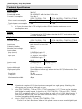
Jazz®
User Guide
JZ20-T10/JZ20-J-T10
▪ 6 Digital Inputs including 2 HSC,
4 Transistor Outputs
JZ20-T18/JZ20-J-T18
▪ 6 Digital Inputs including 2 HSC, 2 Analog/Digital Inputs,
2 Analog Inputs, 8 Transistor Outputs
JZ20-J-T20HS
▪ 6 Digital Inputs including 3 HSC/Shaft-encoder,
2 Analog/Digital Inputs, 2 Analog Inputs,
10 Transistor Outputs
General Description
The products listed above are micro-PLC+HMIs, rugged programmable logic controllers that comprise
built-in operating panels.
Detailed Installation Guides containing the I/O wiring diagrams for these models, technical specifications,
and additional documentation are located in the Technical Library in the Unitronics website:
https://unitronicsplc.com/support-technical-library/
Alert Symbols and General Restrictions
When any of the following symbols appear, read the associated information carefully.
Symbol
Meaning
Description
Danger
The identified danger causes physical and property damage.
Warning
The identified danger could cause physical and property damage.
Caution
Caution
Use caution.
▪ Before using this product, the user must read and understand this document.
▪ All examples and diagrams are intended to aid understanding, and do not guarantee operation.
Unitronics accepts no responsibility for actual use of this product based on these examples.
▪ Please dispose of this product according to local and national standards and regulations.
▪ Only qualified service personnel should open this device or carry out repairs.
▪ Failure to comply with appropriate safety guidelines can cause severe injury or property
damage.
▪ Do not attempt to use this device with parameters that exceed permissible levels.
▪ To avoid damaging the system, do not connect/disconnect the device when power is on.
Environmental Considerations
▪ Do not install in areas with: excessive or conductive dust, corrosive or flammable gas,
moisture or rain, excessive heat, regular impact shocks or excessive vibration, in
accordance with the standards given in the product’s technical specification sheet.
▪ Do not place in water or let water leak onto the unit.
▪ Do not allow debris to fall inside the unit during installation.
▪ Ventilation: 10mm space required between controller’s top/bottom edges & enclosure walls.
▪ Install at maximum distance from high-voltage cables and power equipment.

Installation Guide
2
Unitronics
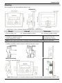
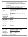
Mounting
Note that figures are for illustrative purposes only.
Dimensions
* * Note that for JZ20-J modules those dimensions are 7.5 mm (0.295”).
Model
Cut-out
View area
JZ20-xxx\JZ20-J-xxx
117 x 89mm (4.606”x 3.504”)
66 x 19.2mm (2.598”x 0.755”)
Add-on modules-
Available by separate order for
communication and cloning.
Integral USB Port
This may be used for
programming purposes.
Note: the USB port and an Add-on module cannot be physically connected at the same time.
Add-on: during installation
Add-on: after installation
USB Port
Installing an Add-on module requires sufficient clearance space
72 mm (2.835")
27.5 mm
(1.083")
38 mm
(1.496")
35.8 mm
(1.409")
DIN-rail mounting
Snap PLC onto the DIN rail
Panel mounting
Note: Removing the unit requires clearance space. Recommendation: approximately 40mm (1.58”)

JZ20-T1X/JZ20-J-T1X/JZ20-J-T20HS
Unitronics
3
Wiring
▪ Do not touch live wires.
▪ This equipment is designed to operate only in SELV/PELV/Class 2/Limited Power
environments.
▪ All power supplies in the system must include double insulation. Power supply outputs
must be rated as SELV/PELV/Class 2/Limited Power.
▪ Do not connect either the ‘Neutral or ‘Line’ signal of the 110/220VAC to device’s 0V pin.
▪ All wiring activities should be performed while power is OFF.
▪ Use over-current protection, such as a fuse or circuit breaker, to avoid excessive currents
into the power supply connection point.
▪ Unused points should not be connected (unless otherwise specified). Ignoring this
directive may damage the device.
▪ Double-check all wiring before turning on the power supply.
Caution
▪ To avoid damaging the wire, do not exceed a maximum torque of:
- Controllers offering a terminal block with pitch of 5mm: 0.5 N·m (5 kgf·cm).
- Controllers offering a terminal block with pitch of 3.81mm f 0.2 N·m (2 kgf·cm).
▪ Do not use tin, solder, or any substance on stripped wire that might cause the wire
strand to break.
▪ Install at maximum distance from high-voltage cables and power equipment.
Wiring Procedure
Use crimp terminals for wiring;
- Controllers offering a terminal block with pitch of 5mm: 26-12 AWG wire (0.13 mm2 –3.31 mm2).
- Controllers offering a terminal block with pitch of 3.81mm: 26-16 AWG wire (0.13 mm2 – 1.31 mm2).
1. Strip the wire to a length of 7±0.5mm (0.270–0.300“).
2. Unscrew the terminal to its widest position before inserting a wire.
3. Insert the wire completely into the terminal to ensure a proper connection.
4. Tighten enough to keep the wire from pulling free.
Wiring Guidelines
▪ Use separate wiring ducts for each of the following groups:
o Group 1: Low voltage I/O and supply lines, communication lines.
o Group 2: High voltage Lines, Low voltage noisy lines like motor driver outputs.
Separate these groups by at least 10cm (4"). If this is not possible, cross the ducts at a 90˚angle.
▪ For proper system operation, all 0V points in the system should be connected to the system 0V
supply rail.
▪ Product-specific documentation must be fully read and understood before performing any wiring.
Allow for voltage drop and noise interference with input lines used over an extended distance.
Use wire that is properly sized for the load.
Earthing the product
To maximize system performance, avoid electromagnetic interference as follows:
▪ Use a metal cabinet.
▪ Connect the 0V and functional ground points (if exist) directly to the earth ground of the system.
▪ Use the shortest, less than 1m (3.3 ft.) and thickest, 2.08mm² (14AWG) min, wires possible.

Installation Guide
4
Unitronics
UL Compliance
The following section is relevant to Unitronics’ products that are listed with the UL.
The following models: JZ20-R10,JZ20-J-R10,JZ20-R16,JZ20-J-R16,JZ20-J-R16HS, JZ20-R31,
JZ20-J-R31,JZ20-J-R31L,JZ20-T10,JZ20-J-T10,JZ20-T18,JZ20-J-T18,JZ20-J-T20HS,JZ20-T40,
JZ20-J-T40,JZ20-UA24, JZ20-J-UA24, JZ20-UN20,JZ20-J-UN20, JZ20-J-ZK2.
are UL listed for Ordinary Location.
UL Ordinary Location
In order to meet the UL ordinary location standard, panel-mount this device on the flat surface of Type 1
or 4 X enclosures
Panel-Mounting
For programmable controllers that can be mounted also on panel, in order to meet the UL Haz Loc
standard, panel-mount this device on the flat surface of Type 1 or Type 4X enclosures.
Communication and Removable Memory Storage
When products comprise either USB communication port, SD card slot, or both, neither
the SD card slot nor the USB port are intended to be permanently connected, while the USB port is
intended for programming only.
Removing / Replacing the battery
When a product has been installed with a battery, do not remove or replace the battery unless the
power has been switched off, or the area is known to be non-hazardous.
Please note that it is recommended to back up all data retained in RAM, in order to avoid losing data
when changing the battery while the power is switched off. Date and time information will also need to
be reset after the procedure.
UL des zones ordinaires:
Pour respecter la norme UL des zones ordinaires, monter l'appareil sur une surface plane de type de
protection 1 ou 4X
Montage de l'écran:
Pour les automates programmables qui peuvent aussi être monté sur l'écran,
pour pouvoir être au standard UL, l'écran doit être monté dans un coffret avec une surface plane de
type 1 ou de type 4X.
Communication et de stockage amovible de mémoire (carte mémoire)
Produits comprend un port USB de communication, soit un port carte SD ou les deux, ni le port SD, ni
le port USB ne sont censés être utilisés en permanence, tandis que l'USB est destiné à la
programmation uniquement.
Retrait / Remplacement de la batterie
Lorsqu'un produit a été installé avec une batterie, retirez et remplacez la batterie seulement si
l’alimentation est éteinte ou si l’environnement n’est pas dangereux.
Veuillez noter qu'il est recommandé de sauvegarder toutes les données conservées dans la RAM, afin
d'éviter de perdre des données lors du changement de la batterie lorsque l'alimentation est coupée. Les
informations sur la date et l'heure devront également être réinitialisées après la procédure

JZ20-T1X/JZ20-J-T1X/JZ20-J-T20HS
Unitronics
5
Inputs
1. All the products comprise I0-I5; these digital inputs are arranged in a single group. Via wiring,
the entire group may be set to either pnp or npn.
2. The following information concerns JZ20-T10/JZ20-J-T10 and JZ20-T18/JZ20-J-T18:
I0 and I1 can function as high-speed counters or as normal digital inputs.
3. The following information concerns JZ20-J-T20HS:
▪ I0, I1, and I4 can function as high-speed counters, as part of a shaft-encoder, or as
normal digital inputs.
▪ I2, I3, and I5 can function as either counter reset, as part of a shaft-encoder, or as
normal digital inputs.
▪ If I0, I1, I4 are set as high-speed counters (without reset), I2, I3, I5 can function as normal
digital inputs.
4. The following information concerns JZ20-T18/JZ20-J-T18 and JZ20-J-T20HS in addition to I0-
I5, these comprise the following:
I6 and I7 may be wired as either digital or analog inputs. These may be wired as either:
▪ npn digital inputs
▪ pnp digital inputs
▪ analog (voltage) inputs
In addition, one input may be wired as a pnp input, while the other is wired as an analog input.
Note that if one input is wired as an npn input, the other may not be wired as an analog input.
5. The following information concerns JZ20-T18/JZ20-J-T18 and JZ20-J-T20HS:
AN0 and AN1 are analog (current) inputs.
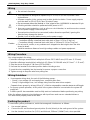
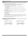
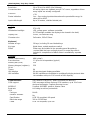
Digital Inputs, Controller’s Power Supply
JZ20-T10/JZ20-J-T10
Input wiring (I0-I5), npn (sink)
Input wiring (I0-I5), pnp (source)

Installation Guide
6
Unitronics
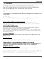
JZ20-T18/JZ20-J-T18
Note: The inputs are arranged in two groups. You can wire one group as npn and the other as pnp,
or wire both groups as npn, or as pnp. In either case, the n/p pins must be connected.
Input wiring (I0-I7), npn (sink)
Input wiring (I0-I7), pnp (source)
Input wiring, (I0-I5), pnp (source), (I6-I7), npn (sink)
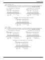
JZ20-J-T20HS
Note: The inputs are arranged in two groups. You can wire one group as npn and the other as pnp,
or wire both groups as npn, or as pnp. In either case, the n/p pins must be connected.
Input wiring (I0-I7), npn (sink)
Input wiring (I0-I7), pnp (source)
Input wiring, (I0-I5), pnp (source), (I6-I7), npn (sink)

JZ20-T1X/JZ20-J-T1X/JZ20-J-T20HS
Unitronics
7
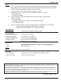
HSC input wiring, npn (sink)
HSC input wiring, pnp (source)
Shaft-encoder wiring, npn (sink)
Shaft-encoder wiring, pnp (source)
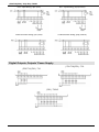
Digital Outputs, Outputs’ Power Supply
JZ20-T10/JZ20-J-T10
JZ20-T18/JZ20-J-T18
JZ20-J-T20HS

Installation Guide
8
Unitronics
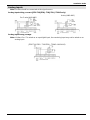
Analog inputs
Note: Shields should be connected at the signal source.
Analog Input wiring, current (JZ20-T18/JZ20-J-T18/JZ20-J-T20HS only)
2 or 3-wire,(AN0-AN1)
4-wire,(AN0-AN1)
Analog Input wiring, voltage
Note: If either I6 or I7 is wired as an npn digital input, the remaining input may not be wired as an
analog input.
JZ20-T18/JZ20-J-T18/JZ20-J-T20HS,(AN2-AN3)

JZ20-T1X/JZ20-J-T1X/JZ20-J-T20HS
Unitronics
9
Technical Specifications
Power supply
Input voltage
24VDC
Permissible range
20.4-28.8VDC with less than 10% ripple
Current Consumption
See Note 1
JZ20-T10/JZ20-J-T10
JZ20-T18/JZ20-J-T18/JZ20-J-T20HS
Max. current consumption
96mA@24VDC
100mA@24VDC
Typical power consumption
1.8W
1.8W
Notes:
1. To If you do not use the LCD backlight, subtract 35mA from the maximum current
consumption value.
Battery
Back-up
7 years typical at 25°C, battery back-up for RTC and system data,
including variable data.
Digital Inputs
Number of inputs
JZ20-T10/JZ20-J-T10
JZ20-T18/JZ20-J-T18/JZ20-J-T20HS
6 (one group) – see Note 2.
8 (two groups) – see Notes 2 & 3
Input type
pnp (source) or npn (sink)
Galvanic isolation
None
Nominal input voltage
24VDC
Input voltage
pnp (source)
0-5VDC for Logic ‘0’
17-28.8VDC for Logic ‘1’
npn (sink)
17-28.8VDC for Logic ‘0’
0-5VDC for Logic ‘1’
I0-I5
I6-I7
Input current
3.7mA@24VDC
1.2mA@24VDC
Response time
10mSec typical
20mSec typical
Input cable length
Up to 100 meters, unshielded
High speed inputs
Specifications below apply when wired as HSC/Shaft-encoder. See
Note 4 & 5.
Resolution
16-bit
Frequency
10kHz maximum
Minimum pulse width
40μs
Notes:
2. All products comprise I0-I5; these inputs are arranged in a single group. Via wiring, the
entire group may be set to either pnp or npn.
3. Only JZ20-T18/JZ20-J-T18 and JZ20-J-T20HS comprises I6 & I7. These may be wired as
either digital or analog inputs, as shown in the JZ20-T18/JZ20-J-T18 and JZ20-J-T20HS
Micro PLC Installation guide. I6 & I7 may be wired as npn, pnp, or 0-10V analog inputs. 1
input may be wired as pnp, while the other is wired as analog. If 1 input is wired as npn,
the other may not be wired as analog.
4. Only in JZ20-T10/JZ20-J-T10 and JZ20-T18/JZ20-J-T18:
• I0 and I1 can each function as either a high-speed counter or as a normal digital input.

Installation Guide
10
Unitronics
• When used as a normal digital input, normal input specifications apply.
5. Only in JZ20-J-T20HS:
• I0, I1, and I4 can function as high-speed counters, as part of a shaft-encoder, or as
normal digital inputs.
• I2, I3, and I5 can function as either counter reset, as part of a shaft-encoder, or as
normal digital inputs.
• If I0, I1, I4 are set as high-speed counters (without reset), I2, I3, I5 can function as
normal digital inputs.
• When used as a normal digital input, normal input specifications apply.
Source Digital Outputs
Number of outputs
JZ20-T10/JZ20-J-T10
JZ20-T18/JZ20-J-T18/JZ20-J-T20HS
4 pnp (source)
8 pnp (source)
Output type
P-MOSFET (open drain)
Isolation
None
Output current
0.5A maximum
Maximum frequency
50Hz (resistive load)
0.5Hz (inductive load)
3kHz (with resistance load< 4kΩ) only O0-O2 in JZ20-J-T20HS
Short circuit protection
Yes
Short circuit indication
Yes
On voltage drop
0.5VDC maximum
Power supply for outputs
Operating voltage
20.4 to 28.8VDC
Nominal voltage
24VDC
Sink Digital Outputs (JZ20-J-T20HS only)
Number of outputs
2 npn (sink)
Output type
N-MOSFET (open drain)
Galvanic Isolation
None
Maximum output current
(resistive load)
100mA per output
HSO freq. range with
resistive load
1Hz-32kHz (at maximum load resistance of 1kΩ)
On voltage drop
1VDC maximum
Short-circuit protection
None
Voltage range
3.5V to 28.8VDC
Analog Inputs
JZ20-T18/JZ20-J-T18/JZ20-J-T20HS only
Number of inputs
4, according to wiring as described above in Note 3
AN0 and AN1
AN2 and AN3
Input range
0-20mA, 4-20mA
0-10VDC
Input impedance
154Ω
20KΩ
Maximum input rating
30mA
28.8V
Galvanic isolation
None
Conversion method
Succesive approximation

JZ20-T1X/JZ20-J-T1X/JZ20-J-T20HS
Unitronics
11
Resolution
10 or 12-bit (0 to 4095) (Via Software)
Conversion time
All analog inputs are updated every 8 PLC scans, regardless of how
many inputs are actually configured.
Precision
2%
Status indication
Yes – if an analog input deviates above the permissible range, its
value will be 4096.
Input cable length
Up to 30 meters, shielded twisted pair
Display
Type
STN LCD
Illumination backlight
LED, yellow-green, software controlled
(LCD backlight; enables the display to be viewed in the dark)
Display size
2 lines, 16 characters long
Character size
5x8 matrix, 2.95x5.55mm
Keyboard
Number of keys
16 keys, including 10 user-labeled keys
Key type
Metal dome, sealed membrane switch
Slides
Slides may be installed in the operating panel faceplate to
custom-label the keys and logo picture. An extra logo slide is
included. A complete set of blank slides is available by separate
order.
Program
Ladder code memory
48K (virtual)
Execution time
1.5 µSec for bit operations (typical)
Memory bits (coils)
256
Memory integers (registers),
16 bit
256
Timers
64
HMI displays
60 user-designed displays available
HMI variables
64 HMI variables are available to conditionally display text and data.
List variables add up to 1.5K's worth of HMI capacity.
Communication
Via a built-in USB port or - Add-On module.See Note 6-9
GSM-support
SMS messages to/from 6 phone GSM numbers, up to 1K of user-
designed messages. Supports Remote Access.
MODBUS
Supports MODBUS protocol, Master-Slave
Baud rate
According to add-on port module
USB
Port type
Mini-B
Galvanic isolation
No
Specification
USB 2.0 compliant; full speed
Baud rate range
300 to 115200 bps
Cable
USB 2.0 compliant; up to 3m

Installation Guide
12
Unitronics
Notes:
6. The JZ20 built-in USB port may be used for programming. Add-on Modules are available
by separate order for communication and cloning. Note that the USB port and an Add-on
module cannot be physically connected at the same time.
7. Add-on module JZ-PRG, with 6-wires communication cable
(supplied in PRG kit – see the JZ-PRG Installation Guide) can be used:
- for programming
- to connect a modem
8. Add-on module JZ-RS4 (RS232/485), with a standard 4-wire communication
cable can be used:
- for programming
- to communicate with other devices (including modems/GSM)
- for RS485 networking.
9. Add-on module MJ20-ET1 enables communication over 100 Mbit/s TCP/IP network:
- Programming/data exchange with Unitronics software;
- Data exchange via MODBUS TCP as Master or Slave.
Miscellaneous
Clock (RTC)
Real-time clock functions (date and time).
Environmental
Operating temperature
0 to 50C (32 to 122F)
Storage temperature
-20 to 60 C (-4 to 140F)
Relative humidity (RH)
10% to 95% (non-condensing)
Mounting method
Panel mounted (IP65/NEMA4X)
DIN-rail mounted (IP20/NEMA1)
Dimensions
Size
147.5X117X46.6mm "5.807 ) X "4.606 X 1.835"). See Note 10
Weight
300 g (10.6 oz)
Notes:
10. For exact dimensions, refer to Page 2.
Mounting
Panel mounting
Insert into cut-out: 117 x 89mm (WxH) 4.606”x 3.504”
DIN-rail mounting
Snap unit onto the DIN rail
The information in this document reflects products at the date of printing. Unitronics reserves the right, subject to all applicable laws, at any time, at its sole
discretion, and without notice, to discontinue or change the features, designs, materials and other specifications of its products, and to either permanently or
temporarily withdraw any of the forgoing from the market.
All information in this document is provided "as is" without warranty of any kind, either expressed or implied, including but not limited to any implied warranties of
merchantability, fitness for a particular purpose, or non-infringement. Unitronics assumes no responsibility for errors or omissions in the information presented in
this document. In no event shall Unitronics be liable for any special, incidental, indirect or consequential damages of any kind, or any damages whatsoever arising
out of or in connection with the use or performance of this information.
The tradenames, trademarks, logos and service marks presented in this document, including their design, are the property of Unitronics (1989) (R"G) Ltd. or other
third parties and you are not permitted to use them without the prior written consent of Unitronics or such third party as may own them
UG_JZ20-T1X_T20HS.pdf 09/22
-
 1
1
-
 2
2
-
 3
3
-
 4
4
-
 5
5
-
 6
6
-
 7
7
-
 8
8
-
 9
9
-
 10
10
-
 11
11
-
 12
12


