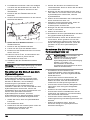
Husqvarna Z454XS Zero Turn Lawn Mower Manuel utilisateur
- Catégorie
- Tondeuses à gazon
- Taper
- Manuel utilisateur

Z454X
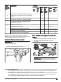
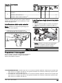
EN Operator's manual 2-33
FR Manuel d'utilisation 34-68
NL Gebruiksaanwijzing 69-101
IT Manuale dell'operatore 102-136
ES Manual de usuario 137-170
DE Bedienungsanweisung 171-205

Contents
Conformity certificates.............................................. 2
Introduction............................................................... 2
Safety........................................................................7
Operation................................................................ 11
Maintenance........................................................... 15
Troubleshooting...................................................... 24
Transportation, storage and disposal......................27
Technical data.........................................................28
Service....................................................................30
EU declaration of conformity...................................32
UK Declaration of conformity ................................. 33
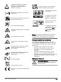
Conformity certificates
USA requirements
Labels are placed on the engine and/or in the engine
compartment stating that the machine will fulfill the
requirements. This is also applicable to special
requirements for any of the states, (California
emission rules etc.). Do not remove these labels.
Certificates can also be supplied with the machine at
delivery or written in the Engine manual. Take care
of them as they are valuable documents.
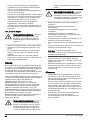
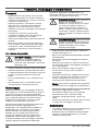
WARNING: Failure to follow
cautious operating practices can result in
dangerous injury to the operator or other
persons. The owner must understand
these instructions, and must let only
approved persons who understand these
instructions to operate the mower. Each
person operating the mower must be of
sound mind and body and must not be
under the influence of mind altering
substances.
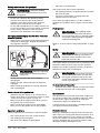
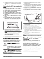
WARNING: The rollover protection
structure can be impaired by damage if
the mower is overturned or if alteration to
the ROPS occurs. If these conditions
take place, the total structure MUST be
replaced.
WARNING: Engine exhaust, some
of its constituents, and certain vehicle
components contain or emit chemicals
known to the State of California to cause
cancer and birth defects or other
reproductive harm.
WARNING: Battery posts, terminals
and related accessories contain lead and
lead compounds, chemicals known to
the State of California to cause cancer
and birth defects or other reproductive
harm. Clean your hands after handling.
WARNING: Engine exhaust and
certain vehicle components contain or
emit chemicals considered to cause
cancer, birth defects, or other
reproductive system damage. The
engine exhaust contains carbon
monoxide, which is an odorless,
colorless, poisonous gas. Do not use the
machine in enclosed spaces.
When this product is worn out and no longer used,
return it to the reseller or other party for recycling.
To implement improvements, specifications and
designs can be altered without prior notification.
Use only original parts for repairs. The use of other
parts voids the warranty.
Do not modify or install non-standard equipment to
the unit without consent from the manufacturer.
Modifications to the unit may cause unsafe
operations or damage the unit.
Introduction
Pre-delivery inspection and product
numbers
A pre-delivery inspection has been done of this
product. Make sure that you receive a signed copy of
the pre-delivery inspection document from your
dealer.
Service agent contact information:
This operator’s manual is for product with product number / serial number:
21741 - 001 - 08.11.2021

/
Engine:
Transmission:
The product numbers are found on the type plate.
Refer to
Product overview on page 3
for the
location of the type plate.
Product description
This product is a ride-on lawn mower. The control
levers let the operator steer the product and adjust
the speed of the product. An hour meter shows how
many hours the product has been used.
Intended use
The product is made to cut grass on open and level
ground only. Do not use the product for other tasks.
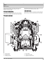
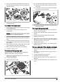
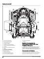
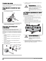
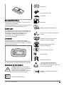
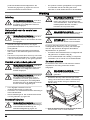
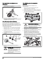
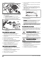
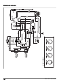
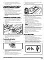
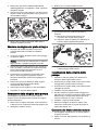
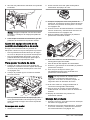
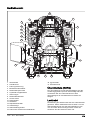
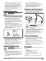
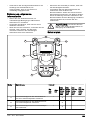
Product overview
5
4
3
16
14
15
13
3
12
11
10
9
8
7
11 12
16
17
1. Control levers
2. Parking brake
3. Tracking control
4. Hour meter
5. Fuel shut-off valve
6. Hydraulic release lever
1741 - 001 - 08.11.2021 3

7. Fuses
8. Fuel tank cap
9. Choke control
10. Ignition switch
11. Throttle control
12. PTO button
13. Fuel gauge
14. Seat adjustment lever
15. Deck lifting lever
16. Type plate
17. ROPS
Roll Over Protection Structure
(ROPS)
ROPS is a protective frame that decreases the risk
of injury if the product overturns. Use the ROPS and
the safety belt when you operate the product on
slopes.
Steering controls
The direction of the product is controlled by the 2
control levers. Refer to
Product overview on page 3
.
The control levers can be moved forward and
rearward from a neutral position. Refer to
To operate
the product on page 13
.
Operator Presence Control (OPC)
The OPC engages when the operator lifts from the
seat. The engine and the drive to the blades stop if
the blades are engaged or the parking brake is not
applied. Refer to
Operation conditions on page 9
.
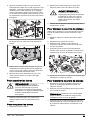
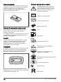
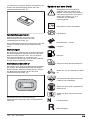
Ignition key
The ignition key has 4 positions:
• Start position (A)
• Run position (B)
• Headlight position (C)
• Stop position (D)
A
B
C
D
Headlights
A
B
C
D
• Turn the ignition key to the headlight position (C)
to operate the product with the headlights on.
• Turn the ignition key to the run position (B) to
operate the product with the headlights off.
Throttle control
The throttle control adjusts the speed of the engine
and the speed of the blades if the blades are
engaged. The throttle control has 2 end positions,
idle speed and full throttle.
AA B
• Idle speed (A) - decreases the engine speed.
• Full throttle (B) - increases the engine speed.
CAUTION: Do not operate the
engine at idle speed (A) for longer time
than necessary. Too much operation
time at idle speed can decrease the life
of the spark plugs.
Choke control
The choke control is used for cold starts to supply
more fuel to the engine. Pull up the choke control
when you start a cold engine.
Refer to
Product overview on page 3
for the position
of the choke control.
PTO (Power Take-Off) button
The PTO button engages and disengages the PTO
clutch and the cutting deck or other equipment
connected to it. The correct start conditions must be
obeyed to engage the drive of the blades. Refer to
Operation conditions on page 9
for the correct
start conditions.
41741 - 001 - 08.11.2021

• Pull the PTO button out to engage the drive to
the blades or other equipment.
• Push the PTO button in to disengage the drive to
the blades or other equipment.
Fuel gauge
The fuel gauge shows the fuel level and will flash
yellow when the fuel level is approximately 1.0
gallons/3.8 l. Refer to
Product overview on page 3
for the position of the fuel gauge.
Fuel shut-off valve
Refer to
Product overview on page 3
for the position
of the fuel shut-off valve.
The fuel shut-off valve is closed when the tab on the
knob is perpendicular to the fuel line.
Fuses
The location of the fuses is in the fuse box. The fuse
box is below the seat. Tilt the seat forward to get
access the fuse box. Refer to the decal on the fuse
box for identification of the different fuses.
Hour meter
The product has an hour meter that show how many
hours of operation that the blades have been
engaged. Refer to
Product overview on page 3
for
the position of the hour meter.
Each 50 hours an oil level symbol will show for 2
hours. Refer to
Lubrication schedule on page 23
.
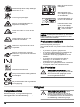
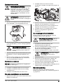
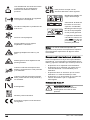
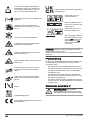
Symbols on the product
WARNING: This product can be
dangerous and cause serious injury or
death to the operator or others. Be
careful and use the product correctly.
Use protective glasses.
Parking brake.
Engine speed – fast.
Slow.
Fuel.
Use protective gloves.
Stop the engine before maintenance.
Do not operate the product without
deflector or grass catcher.
1741 - 001 - 08.11.2021 5

Always use approved hearing
protection.
Do not put your foot here.
Neutral gear.
Reverse gear.
Read the operator's manual carefully
and make sure that you understand the
instructions before you use the product.
Keep a safe distance from the product.
Do not operate the product on slopes
larger than 10°.
Do not keep passengers.
Look out for ejecting objects and
ricochets.
Keep hands and feet clear.
Keep hands away from rotating parts.
Look out for persons and animals when
you operate the product forward.
Look out for persons and animals when
you operate the product rearward.
Choke.
Sound power level.
The product agrees with the applicable
EC directives.
This product conforms to the applicable
UK regulations.
Keep away from the dis-
charge deck.
Warning! Battery acid is
corrosive, explosive and
flammable.
Keep body parts away
from rotating parts.
yyyywwxxxx The rating plate shows
serial number. yyyy is
the production year and
ww is the production
week.
Note: Other symbols/decals on the product refer
to certification requirements for some commercial
areas.
Product liability
As referred to in the product liability laws, we are not
liable for damages that our product causes if:
• the product is incorrectly repaired.
• the product is repaired with parts that are not
from the manufacturer or not approved by the
manufacturer.
• the product has an accessory that is not from the
manufacturer or not approved by the
manufacturer.
• the product is not repaired at an approved
service center or by an approved authority.
Euro V Emissions
WARNING: Tampering with the
engine voids the EU type-approval of
this product.
61741 - 001 - 08.11.2021

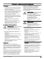
Safety
Safety definitions
Warnings, cautions and notes are used to point out
specially important parts of the manual.
WARNING: Used if there is a risk of
injury or death for the operator or
bystanders if the instructions in the
manual are not obeyed.
CAUTION: Used if there is a risk of
damage to the product, other materials
or the adjacent area if the instructions in
the manual are not obeyed.
Note: Used to give more information that is
necessary in a given situation.
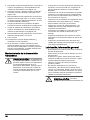
General safety instructions
WARNING: Read the warning
instructions that follow before you use
the product
WARNING: This product is capable
of amputating hands and feet and
throwing objects. Failure to observe the
following safety instructions could result
in serious injury or death.
• Read, understand, and follow instructions and
warnings in this document, the operator’s manual
and on the product, engine and attachments.
• Only allow operators, who are responsible,
trained, familiar with the instructions, and
physically capable to operate the product.
• Do not carry passengers and keep bystanders
away.
• Do not operate the product while under the
influence of alcohol or drugs.
• Follow the manufacturer’s recommendation for
wheel weights or counterweights.
• Learn how to use the product and its controls
safely and learn how to stop the product quickly.
• Learn to recognize the safety decals.
• Keep the product clean to make sure that you
can clearly read signs and stickers.
• Keep in mind that the operator will be held
responsible for accidents that involve other
persons or their property.
• Only use the product in daylight or in other well-lit
conditions. Keep the product at a safe distance
from holes or other irregularities in the ground.
Look out for other possible risks.
• Do not let children or other persons not approved
for operation of the product to use or do servicing
on it. Local laws may regulate the age of the
user.
• Make sure that nobody else is in the vicinity of
the product when you start the engine, engage
the drive or start to move the product.
• Keep an eye on the traffic when you mow near a
road or move across a road.
• Do not use the product if you are fatigued, while
under the influence of alcohol or drugs, medicine
or anything that can have a negative effect on
your vision, alertness, coordination or judgement.
• Always park the product on a level surface with
the engine stopped.
Safety instructions regarding children
WARNING: Read the warning
instructions that follow before you use
the product.
• Tragic accidents can occur if the operator is not
alert to the presence of children. Children are
often attracted to the product and the mowing
activity. Never assume that children will remain
where you last saw them.
• Keep children out of the operating area and
under the watchful care of a responsible adult
other than the operator.
• Do not carry children, even with the blade(s) shut
off. Children could fall off and be seriously injured
or interfere with safe product operation. Children
who have been given rides in the past could
suddenly appear in the mowing area for another
ride and be run over or backed over by the
product.
Safety instructions for operation
WARNING: Read the warning
instructions that follow before you use
the product.
WARNING: Do not touch the
engine or exhaust system during or
directly after operation. The engine and
the exhaust system become very hot
during operation. Risk of burn injuries,
fire and damage to property or adjacent
areas. When you operate the product,
keep away from bushes and other
objects.
• Only operate the engine in well ventilated areas.
Exhaust gases contain carbon monoxide, a
deadly poison.
1741 - 001 - 08.11.2021 7

• Only operate the product in daylight or good
artificial light.
• Avoid holes, ruts, bumps, rocks, or other hidden
hazards. Uneven terrain could overturn the
product, or cause operator to lose their balance
or footing.
• Do not put hands or feet near rotating parts or
under the product. Keep clear of the discharge
opening at all times.
• Do not direct discharge material toward anyone.
Avoid discharging material against a wall or
obstruction. Material may ricochet back toward
the operator. Stop the blade(s) when crossing
gravel surfaces.
• Do not leave a running product unattended.
Always park on level ground, disengage the
attachment, set parking brake, and stop engine/
motor.
• Do not mow in reverse unless absolutely
necessary. Always look down and behind before
and while backing.
• Decrease the speed before you turn around a
corner.
Safety instructions for operation on slopes
WARNING: Read the warning
instructions that follow before you use
the product.
Slopes are a major factor related to accidents.
Operation on slopes requires extra caution.
• Travel in the manufacturer recommended
direction on slopes. Use caution while operating
near dropoffs.
• Avoid mowing wet grass. (Poor footing could
cause a slip and fall accident.)
• Do not operate product under any condition
where traction, steering, or stability is in question.
Tires could slide even if the wheels are stopped.
• Always keep the product in gear when going
down slopes. Do not coast downhill.
• Avoid starting and stopping on slopes. Avoid
making sudden changes in speed or direction.
Make turns slowly and gradually.
• Use extra care while operating product with a
grass catcher or other attachment(s). They can
affect the stability of the product.
• To cut grass on slopes increases the risk that
you can not control the product and that it
overturns. This can cause injury or death. It is
necessary to cut the grass carefully on all slopes.
If you cannot reverse up a slope or if you do not
feel safe, do not cut it.
• Remove stones, branches and other obstacles.
• Cut the grass on the slope up and down, not
from side to side.
• Do not operate the product on ground that slopes
more than 10°.
• Move smoothly and slowly on slopes.
• Look out for and do not move across furrows,
holes and bumps. There is a higher risk that the
product overturns on ground that is not flat. Long
grass can hide obstacles.
• Do not cut grass near edges, ditches or banks.
The product can suddenly overturn if a wheel
moves across the edge of a steep slope or a
ditch, or if an edge gives way.
Safety instructions for operation on slopes
• The ROPS is an integral and effective safety
device. Do not remove or alter the ROPS.
• Keep a folding ROPS in the raised and locked
position and use the seat belt when operating the
product.
• Lower a folding ROPS temporarily only when
absolutely necessary. Do not wear the seat belt
when folded down. There is no rollover protection
when a folding ROPS is in the down position.
• Replace a damaged ROPS. Do not repair or
alter.
Personal protective equipment
WARNING: Read the warning
instructions that follow before you use
the product.
• Use approved personal protective equipment
when you use the product. Personal protective
equipment cannot fully prevent injury but it
decreases the degree of injury if an accident
does occur. Let your dealer help you select the
right equipment.
• Always wear approved hearing protection. Long
term exposure to noise can result in permanent
hearing impairment.
• Always wear protective shoes or protective
boots. Steel toes are recommended. Do not use
the product barefoot.
• Wear gloves when necessary, for example when
you attach, examine or clean the cutting
equipment.
• Do not wear loose-fitting clothing, jewelry or
other items that can get caught in moving parts.
• Keep first aid equipment and fire extinguisher
close at hand.
81741 - 001 - 08.11.2021

Safety devices on the product
WARNING: Read the warning
instructions that follow before you use
the product.
• Do not use a product with defective safety
devices. Do a check of the safety devices
regularly. If the safety devices are defective,
speak to your Husqvarna service agent.
• Do not make modifications on safety devices. Do
not use the product if protective plates, protective
covers, safety switches or other protective
devices are not attached or are defective.
To engage and disengage the Roll Over Protection
Structure (ROPS)
• Remove the 2 pins that hold the ROPS and fold it
rearwards to disengage. Engage the ROPS in
the opposite sequence.
WARNING: Obey the following
instructions for the ROPS and the
safety belt.
• Do not use the safety belt if the ROPS is
disengaged.
• Always use the safety belt when the ROPS is
engaged.
• Make sure that the ROPS is correctly attached
and not damaged.
To do a check of the ignition lock
• Start and stop the engine to do a check of the
ignition lock. Refer to
To start the engine on page
13
and
To stop the engine on page 14
.
• Make sure that the engine starts when you turn
the ignition key to start position.
• Make sure that the engine stops immediately
when you turn the ignition key to stop position.
Operation conditions
These conditions are necessary to start the engine:
• The control levers are in the neutral position.
• The parking brake is applied.
• The drive of the blades is disengaged.
• The OPC is pushed down.
The engine must stop in these situations:
• The parking brake is not applied and the operator
lifts from the seat.
• The drive of the blades is engaged and the
operator lifts from the seat.
Try to start the engine without 1 of the conditions.
Change the conditions and try again. Do this check
daily.
Parking brake
WARNING: If the parking brake
does not work, the product can start to
move and cause injury or damage. Make
sure that the parking brake is regularly
examined and adjusted.
Refer to
To do a check of the parking brake on page
18
.
Muffler
WARNING: Do not use the product
if the muffler is missing or defective. A
defective muffler increases the noise
level and the risk of fire.
The muffler keeps the noise levels to a minimum and
sends the exhaust fumes away from the operator.
Examine the muffler regularly to make sure that it is
attached correctly and not damaged.
WARNING: The muffler becomes
very hot during and after use and when
the engine operates at idle speed. Be
careful near flammable materials and/or
fumes to prevent fire.
To do a check of the muffler
• Examine the muffler regularly to make sure that it
is attached correctly and not damaged.
Spark arrestor
This product has an internal-combustion engine. Do
not use the product near vegetation without a spark
arrestor that is approved by local or state laws.
Federal laws apply on federal lands.
A spark arrestor for the muffler is available through
your approved Husqvarna dealer.
Protective covers
Missing or damaged protective covers increase the
risk of injury on moving parts and hot surfaces. Do a
check of the protective covers before you operate
the product. Make sure that the protective covers are
correctly attached and do not have cracks or other
damages. Replace damaged covers.
1741 - 001 - 08.11.2021 9

Fuel safety
WARNING: Read the warning
instructions that follow before you use
the product.
WARNING: Be careful with fuel. It
is very flammable, and can cause injury
and damage to property.
• Extinguish all cigarettes, cigars, pipes and other
sources of ignition.
• Use only an approved fuel container.
• Do not remove fuel cap or add fuel with the
engine running or while hot.
• Do not refuel indoors or in enclosed spaces.
• Do not store the product or fuel container, or
refuel, where there is an open flame, spark, or
pilot light such as on a water heater or other
appliance.
• If fuel is spilled, do not attempt to start the engine
and avoid creating any source of ignition until
fuel vapors have dissipated.
• To help prevent fires: keep product free of grass,
leaves, or other debris build up; clean up oil or
fuel spillage and remove any fuel soaked debris;
allow product to cool before storing.
• Use extra care in handling gasoline and other
fuels. They are flammable and vapors are
explosive.
• Gasoline and gasoline fumes are poisonous and
very flammable. Be careful with gasoline to
prevent injury or fire.
• Let the engine become cool before you refuel.
• Do not fill fuel near sparks or naked flames.
• If there are leaks in the fuel system, do not start
the engine until the leaks are repaired.
• Do not fill above recommended fuel level. The
heat from the engine and the sun makes the fuel
expand and the fuel overflows if the tank is filled
too much.
• Store the product and fuel in such a way that
there is no risk that fuel leaks or fumes can
cause damage.
Transport safety
• Use an approved transport vehicle for
transportation of the product.
• A markets national or local regulations can set
limit to the transportation of the product.
• The operator of the transport vehicle is
responsible to attach the product safely during
transport. Refer to
Transportation on page 27
.
Hauling
• Use full width ramps for loading and unloading a
product for transport.
Towing safety
• Follow the manufacturer’s recommendation for
weight limits for towed equipment and towing on
slopes.
• Only use tow equipment approved by
Husqvarna.
• Use the tow bar to attach the equipment.
• Make sure that no other persons are near the
product when you tow equipment.
• Do not let children or others in or on the towed
equipment.
• Do not tow on slopes or rough ground. The
weight of the towed equipment can cause loss of
traction and loss of control.
Battery safety
WARNING: A damaged battery can
cause an explosion and cause injury. If
the battery has a deformation or is
damaged, speak to an approved
Husqvarna service agent.
WARNING: Read the warning
instructions that follow before you use
the product.
• Use protective glasses when you are near
batteries.
• Do not wear watches, jewelry or other metal
objects near the battery.
• Keep the battery out of reach for children.
• Charge the battery in a space with good airflow.
• Keep flammable materials at a minimum
clearance of 1 m when you charge the battery.
• Discard replaced batteries. See
Disposal on
page 27
.
• Explosive gases can come from the battery. Do
not smoke near the battery. Keep the battery
away from open flames and sparks.
Safety instructions for maintenance
WARNING: Read the warning
instructions that follow before you use
the product.
WARNING: The product is heavy
and can cause injury or damage to
property or the adjacent area. Do not do
maintenance on the engine or the cutting
deck without these conditions:
• The engine is off.
• The product is parked on a level
surface.
• The parking brake is applied.
• The ignition key in stop position and
removed.
10 1741 - 001 - 08.11.2021

• The blades are disengaged.
• All moving parts have stopped.
• The ignition cables are removed from
the spark plugs.
WARNING: Fluid escaping under
pressure may have sufficient force to
penetrate skin and cause serious injury.
If fluid is injected into the skin, seek
immediate medical attention. Keep body
and hands away from pin holes or
nozzles that eject fluid under high
pressure. If a leak occurs, have the
product immediately serviced by a
trained technician.
WARNING: The exhaust fumes
from the engine contain carbon
monoxide, an odorless, poisonous and
very dangerous gas. Do not run the
product in closed spaces or spaces with
no sufficient air flow.
• Keep the product in good working order. Replace
worn or damaged parts.
Use caution when servicing blades. Wrap the
blade(s) or wear gloves. Replace damaged
blades. Do not repair or alter blade(s).
If equipped, disconnect spark plug wire(s) and
the negative battery cable before making any
repairs.
For best performance and safety, do
maintenance on the product regularly as given in
the maintenance schedule. Refer to
Maintenance
schedule on page 15
.
• Electrical shocks can cause injuries. Do not
touch the cables when the engine is on. Do not
do a function test on the ignition system with your
fingers.
• Let the product become cool before you do
maintenance near the engine.
• The blades are sharp and can cause cuts. Wind
protection around the blades or use protective
gloves when you do work on the blades.
• Do not turn the engine over if the spark plug or
ignition cable is removed.
• Make sure that all nuts and bolts are tightened
correctly and that the equipment is in good
condition.
• Do not change the adjustment of governors. If
the engine speed is too high, the product
components can become damaged. Refer to
Technical data on page 28
for highest permitted
engine speed.
• The product is approved only with the equipment
supplied or recommended by the manufacturer.
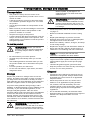
Operation
Introduction
WARNING: Before you operate the
product, you must read and understand
the safety chapter.
To operate the product for the first
time
WARNING: Before you operate the
product for the first time, you must read
and understand the this chapter.
• Use a decreased throttle speed and a decreased
ground speed when you operate the product for
the first time.
• Do not move the control levers to the fully
forward position or the fully reverse position
during the initial operation.
• Learn how to operate the movement of the
product on a hard surface, for example concrete
or asphalt, before you operate the product on a
lawn for the first time.
To do before you operate the
product
WARNING: Before you operate the
product, you must read and understand
the safety chapter.
WARNING: Before you operate the
product, you must make sure that there
are no stones or other objects in the
work area that can be thrown by the
rotating blades.
• Do the daily maintenance. Refer to
Maintenance
schedule on page 15
.
• Make sure that there is sufficient fuel in the fuel
tank.
• Set the cutting height. Refer to
Maintenance
schedule for the operator on page 15
.
To fill fuel
WARNING: Gasoline is very
flammable. Be careful and refuel
outdoors, refer to
Fuel safety on page
10
.
1741 - 001 - 08.11.2021 11

WARNING: The engine and the
exhaust system become very hot during
operation. Risk of burn injury. Let the
engine and the exhaust system become
cool before you fill fuel in the product.
WARNING: Do not use the fuel
tank as a support area.
CAUTION: Incorrect type of fuel can
result in engine damage.
The engine runs on gasoline with a minimum octane
rating of 91 RON (87 AKI), not mixed with oil. We
recommend biodegradable alkylate gasoline.
• Do a check of the fuel level before each use and
refuel if it is necessary.
• Do not fill the fuel tank fully. Fill to the bottom of
the fuel tank neck.
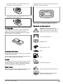
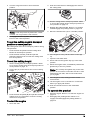
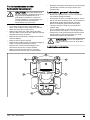
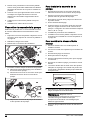
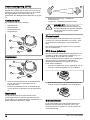
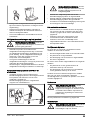
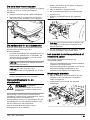
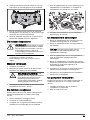
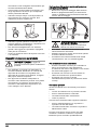
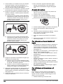
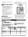
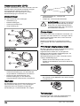
To adjust the seat
The position of the seat can be moved forward or
rearward and suspension of the seat can be
adjusted.
WARNING: Do not make
adjustments to the seat when the
product is in operation.
• Turn the knob below the seat (A) to adjust the
seat suspension. Turn the knob counterclockwise
for soft suspension and clockwise for hard
suspension.
B
A
• Push the lever below the seat (B) to the side and
push the seat forward or rearward.
To fold the seat
The seat can be folded forward to get access to the
battery and hydrostatic transmission system.
1. Park the product on level ground.
2. Push the lever and push the backrest of the seat
forward to fold the seat forward.
To engage and disengage the
parking brake
This product has no dedicated parking brake lever.
The parking brake is integrated in the 2 control
levers.
• Push the 2 control levers away from the seat at
the same time to engage the parking brake.
Refer to
Product overview on page 3
for the
location of the control levers.
Note: The product must be stationary when
you engage the parking brake.
Note: The engine will stop if you do not push
the 2 control levers away from the seat at the
same time.
• Pull the 2 control levers in the direction of the
seat to disengage the parking brake.
To disengage and engage the drive
system
CAUTION: Only disengage or
engage the drive system when the
product is parked on level ground.
If it is necessary to move the product by hand, with
the engine off, the drive system must be disengaged.
The drive system is disengaged and engaged by the
bypass valves. The bypass valves are found on the
front of each transmission.
Follow the procedure below to disengage the drive
system.
1. Park the product on level ground and stop the
engine.
2. Set the cutting deck to the lowest position.
3. Set the control levers in neutral position.
4. Lift the seat.
12 1741 - 001 - 08.11.2021

5. Turn the 2 bypass levers to the horizontal
position.
Note: Push the product by hand onto a truck
or trailer. Do not push the control levers.
6. To engage the drive system, turn the bypass
levers to the vertical position.
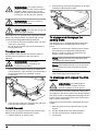
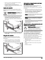
To set the cutting deck in transport
position or mow position
The cutting deck must be in transport position during
transportation.
• Push the deck lift pedal until the cutting deck
latches in the transport position.
• Push the deck release pedal and pull the
transport release lever to lower the cutting deck
into mow position.
To set the cutting height
1. Set the cutting deck in transport position. Refer
to
To set the cutting deck in transport position or
mow position on page 13
.
2. Put the pin (A) in the hole for the correct cutting
height.
A
B
C
3. Push the deck lift pedal (B) and pull the transport
release lever (C) rearward to lower the cutting
deck into mow position.
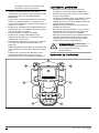
To start the engine
1. Sit on the seat.
2. Push the PTO button to disengage the drive on
the cutting deck.
3. Set the cutting deck in transport position. Refer
to
To set the cutting deck in transport position or
mow position on page 13
.
4. Engage the parking brake. Refer to
To engage
and disengage the parking brake on page 12
.
5. Move the throttle lever (A) to ½ throttle position.
A
BC
6. If the engine is cold, pull the choke control (B)
up.
7. Open the fuel tank valve.
8. Press and turn the ignition key (C) to the start
position.
9. When the engine starts, immediately release the
ignition key to the run position.
Note: Do not keep the ignition key in the start
position for more than 5 seconds at a time. If the
engine does not start, wait 15 seconds before
you try again.
10. If the engine is cold, slowly push the choke
control down.
11. Let the engine run at ½ throttle for 3-5 minutes
before you apply full throttle.
12. Push the throttle control to the full throttle
position.
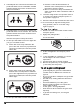
To operate the product
1. Start the engine. Refer to
To start the engine on
page 13
.
2. Disengage the parking brake. Refer to
To
engage and disengage the parking brake on
page 12
.
1741 - 001 - 08.11.2021 13

3. Carefully push the 2 control levers forward. The
product will start to move forward. The forward
speed increases the more the 2 control levers
are pushed forward.
4. Carefully pull the 2 control levers rearward. The
product will start to move rearward. The rearward
speed increases the more the 2 control levers
are pulled rearward.
5. Put the 2 control levers in neutral position to
decrease the speed and stop the product.
6. Do the steps that follow to turn left or right when
you go in a forward direction.
a) Pull the left control lever rearward in the
direction of the neutral position to make the
product turn left. The more you pull the left
control lever rearward, the more the product
will turn left.
b) Pull the right control lever rearward in the
direction of the neutral position to make the
product turn right. The more you pull the right
control lever rearward, the more the product
will turn right.
7. Do the steps that follow to make a zero turn.
a) Pull the 2 control levers rearward in the
direction of the neutral position to decrease
the speed or stop the product.
b) Move 1 control lever slightly forward and the
other control lever slightly rearward to make a
zero turn.
8. Lower the cutting deck to mow position. Refer to
To set the cutting deck in transport position or
mow position on page 13
.
9. Pull up the PTO button to engage the drive of the
blades.
10. If it is necessary to adjust the cutting height
during operation, refer to
To set the cutting
height on page 13
.
To stop the engine
1. Move the 2 control levers to the neutral position
to stop the product.
2. Engage the parking brake.
3. Push down the PTO button to disengage the
drive of the blades.
4. Put the cutting deck in the transport position.
5. Move the throttle control to the minimum throttle
position.
6. Let the engine idle for a minimum of 1 minute
until the engine is at usual operation
temperature.
7. Turn the ignition key to the stop position.
8. Remove the ignition key from the ignition when
you are away from the product.
To get a good cutting result
• For best performance, do maintenance on the
product regularly as given in the maintenance
schedule. Refer to
Maintenance schedule on
page 15
.
• Do not cut a wet lawn. Wet grass can give a bad
cutting result.
• Start with a high cutting height and decrease it
gradually.
• Use full throttle when you cut the grass.
• Move the product forward at low speed if the
grass is high and thick.
• Cut the grass in an irregular pattern.
• When the mulch kit is used, cut the grass more
frequently.
• To get the best cutting result, cut the grass
frequently.
14 1741 - 001 - 08.11.2021

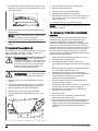
To do a 3-point turn
A correct turn will prevent damage to the lawn. The
goal is to turn when you move forward or rearward.
Do not turn in a tight circle on a stopped wheel.
1. Cut a row of grass.
2. Make a small turn (A) in the direction of the uncut
area of grass.
A
B
C
3. Pull the 2 control levers to the reverse position
and move the product rearward (B).
4. Push the control levers forward. To make a small
turn (C), pull harder on the control lever that is in
the direction of the row you have cut before.
5. Push the 2 control levers forward to cut the next
row.
Maintenance
Introduction
WARNING: Before you do any
maintenance work you must read and
understand the safety chapter.
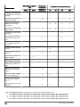
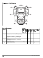
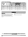
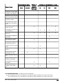
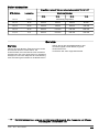
Maintenance schedule
* = The instructions are not given in this operator's
manual.
X = The instructions are given in this operator's
manual.
O = Refer to the engine manual for instructions.
Maintenance schedule for the operator
Maintenance
Daily maintenance Do mainte-
nance at a
minimum of
1 time each
year
Maintenance interval in hours
Before After 25 50 100 300
Do a check of the parking
brake. X * *
Do a check of the level of
the engine oil. O
Do a check of the safety
system. X
Make sure that there are
no fuel or oil leaks from
the product.
*
1741 - 001 - 08.11.2021 15

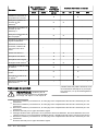
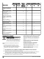
Maintenance
Daily maintenance Do mainte-
nance at a
minimum of
1 time each
year
Maintenance interval in hours
Before After 25 50 100 300
Make sure that there are
no damage on the prod-
uct.
*
Make sure that there are
no loose parts. *
Do a check for damages
on the cutting deck. *
Do a check of the cutting
deck for adjustment. X X
Do a check of the tire
pressures. X X X X
Do a check of the battery
connections. X X X X X
Do a check of the throttle
cable. O
Do a check of the caster
wheels (each 200 hours). X X
Do a check of the clear-
ance of the engine
valve.1
* *
Clean the air intake of the
engine. O O
Clean the air intake of the
engine.2O O
Clean the bottom side of
the cutting deck. X
Clean around the engine. *
Clean around the belts
and the belt pulleys. * * * *
Do a check of the belts
and the belt pulleys. X X
Clean the foam pre-filter
(if equipped).3O O
Replace the foam pre-fil-
ter (if equipped).4O
Clean the paper filter car-
tridge.5O O
1Must be done by approved service agent.
2In conditions with dust, cleaning and replacement must be done more frequently.
3In conditions with dust, cleaning and replacement must be done more frequently.
4In conditions with dust, cleaning and replacement must be done more frequently.
5In conditions with dust, cleaning and replacement must be done more frequently.
16 1741 - 001 - 08.11.2021

Maintenance
Daily maintenance Do mainte-
nance at a
minimum of
1 time each
year
Maintenance interval in hours
Before After 25 50 100 300
Examine the muffler and
spark arrestor screen. * * * *
Start the engine and
blades and listen for un-
usual sounds.
*
Sharpen the blades.6X X
Replace the blades. X X
Replace the spark plugs. O O
Replace the engine oil.7O O
Replace the engine oil fil-
ter. O O
Replace the fuel filter. O O
Replace the paper air fil-
ter.8O O
Do the 300-hour servic-
ing.9* *
To clean the product
CAUTION: Do not use a high-
pressure washer or a steam cleaner.
Water can go into bearings and electrical
connections and cause corrosion which
causes damage to the product.
Clean the product immediately after use.
• Do not clean hot surfaces such as the engine,
muffler and exhaust system. Wait until the
surfaces are cool, then remove the grass or dirt.
• Before you clean with water, clean with a brush.
Remove grass and dirt on and around the
transmission, the transmission air intake, and the
engine.
• Use running water from a hose to clean the
product. Do not use high-pressure.
• Do not point the water at electrical components
or bearings. Detergent usually increases the
damage.
• Use compressed air to clean the top side of the
mower deck.
• Use a water hose to clean below the cutting
deck.
• When the product is clean, start the cutting deck
for a short period to remove remaining water.
To clean the engine and the muffler
Keep the engine and muffler free from grass cuttings
and dirt. Grass cuttings soaked in fuel or oil on the
engine can increase the fire risk and the risk that the
engine becomes too hot. Let the engine cool before
it is cleaned. Clean with water and a brush.
Grass cuttings around the muffler dry quickly and are
a fire risk. Use a brush or remove the grass cuttings
with water when the muffler is cold.
To clean the battery
Corrosion and dirt on the battery and the terminals
can cause the power of the battery to decrease.
1. Remove the battery. Refer to
To remove and
install the battery on page 18
.
2. Flush the battery with water and let dry.
CAUTION: Do not use a high-
pressure washer or a steam cleaner.
Water can go into bearings and
electrical connections and cause
6Must be done by approved service agent.
7Replace the engine oil after the first 8-10 hours of operation. During heavy load or high ambient tem-
peratures, replace the engine oil each 50 hours.
8In conditions with dust, cleaning and replacement must be done more frequently.
9Must be done by approved service agent.
1741 - 001 - 08.11.2021 17

corrosion which causes damage to
the product.
3. Clean the terminals and the cable ends of the
battery cables with a wire brush.
To do a check of the parking brake
1. Park the product on a slope with a hard surface.
Note: Do not park the product on a grass
slope when you do a check of the parking brake.
2. Engage the parking brake.
3. If the product starts to move with the parking
brake engaged, let an approved service agent
adjust the parking brake.
4. Disengage the parking brake.
To charge the battery
• Charge the battery if it is too weak to start the
engine. Refer to
Battery charging times on page
30
for battery charging times.
• Use a standard battery charger.
CAUTION: Do not use a boost
charger or start booster. A boost
charger or a start booster will cause
damage to the electrical system of
the product.
• Always disconnect the battery charger before
you start the engine.
To do an emergency start of the
engine
If the battery is too weak to start the engine, you can
use jumper cables to do an emergency start. This
product has a 12 V system with negative ground.
The product that is used for the emergency start
must also have a 12 V system with negative ground.
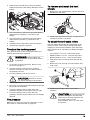
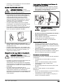
To connect the jumper cables
WARNING: Risk of explosion
because of explosive gas that comes
from the battery. Do not connect the
negative terminal of the fully charged
battery to or near the negative terminal
of the weak battery.
CAUTION: Do not use the battery of
the product to start other vehicles.
1. Connect one end of the red cable to the
POSITIVE battery terminal (+) on the weak
battery (A).
B
A
C
D
2. Connect the other end of the red cable to the
POSITIVE battery terminal (+) on the fully
charged battery (B).
WARNING: Do not short circuit
the ends of the red cable against the
chassis.
3. Connect one end of the black cable to the
NEGATIVE battery terminal (-) on the fully
charged battery (C).
4. Connect the other end of the black cable to a
CHASSIS GROUND (D), away from the fuel tank
and the battery.
To remove the jumper cables
Note: Remove the jumper cables in the opposite
sequence to how you connect them.
1. Remove the BLACK cable from the chassis.
2. Remove the BLACK cable from the fully charged
battery.
3. Remove the RED cable from the 2 batteries.
To remove and install the battery
1. Fold the seat forward. Refer to
To fold the seat
on page 12
.
18 1741 - 001 - 08.11.2021

2. Remove the bolt and the nut from the battery
bracket and remove the battery bracket from the
battery.
3. Use 2 wrenches to disconnect the black battery
cable from the negative (–) terminal on the
battery.
4. Use 2 wrenches to disconnect the red battery
cable from the positive (+) terminal on the
battery.
5. Carefully remove the battery from the product.
6. Install in the opposite sequence.
To adjust the tracking speed
If the product does not move straight forward, the
tracking speed must be adjusted.
WARNING: Always adjust the
tracking speed in an open area without
bystanders.
1. Do a check of the tire pressure. Refer to
Tire
pressure on page 19
.
2. Turn the tracking controls fully in. Refer to
Product overview on page 3
for the location of
the tracking controls.
3. Turn the tracking controls out 4 turns.
CAUTION: More than 4 turns
can cause damage to the product.
4. Start the product.
5. Move the control levers forward fully and operate
the product at full throttle.
6. Turn the tracking control on the right side
gradually until the product starts to move right.
7. Turn the tracking control on the left side
gradually until the product starts to move straight
forward.
Tire pressure
Make sure to have the correct tire pressure on all 4
tires. Refer to
Technical data on page 28
.
To remove and install the front
wheels
1. Remove the nut and the bolt to remove the front
wheels from the forks.
2. Install in the opposite sequence. Torque the nut
and bolt to 50 ft-lbs / 67.8 Nm.
To adjust the anti-scalp rollers
The anti-scalp rollers keep the cutting deck in the
correct position on the ground and prevent lawn
scalping in most terrain conditions. The anti-scalp
rollers can be set in 3 positions for different lengths
of grass:
• Top position: 1.5–2.5 in. / 38–64 mm grass.
• Middle position: 2.5–4 in. / 64–102 mm grass.
• Bottom position: 4–5 in. / 102–127 mm grass.
1. Park the product on level ground and stop the
engine.
2. Remove the nut, the bolt, the axle and the anti-
scalp roller.
3. Install the anti-scalp roller in one of the 3
positions.
CAUTION: The cutting deck can
become damaged if the anti-scalp
rollers are incorrectly adjusted. The
anti-scalp rollers must be
approximately 1/4 in. / 6.4 mm from
the ground.
1741 - 001 - 08.11.2021 19

To adjust the parallelism of the
cutting deck
This procedure will set the cutting deck in a standard
position.
1. Make sure that the tire pressure is correct. Refer
to
Tire pressure on page 19
.
2. Park the product on a level surface.
3. Turn the outer blade tips to align with the cutting
deck side to side.
WARNING: The blades on the
cutting deck are sharp and can
cause injury. Use protective gloves.
4. Measure the distance between the ground and
the bottom of the blade tip on the discharge side
of the cutting deck. Make a note of the distance.
5. Measure the distance between the ground and
the bottom of the blade tip on the side opposite
to the discharge side. The distance must be the
same as the distance for the discharge side. If
adjustment is necessary, adjust the locknut on
the top of the rear links until the 2 side to side
distances are equal.
6. Turn the 2 outer blades to align with the cutting
deck front to rear.
7. Adjust the 2 front bolts until the rear blade tips
are set 1/8–3/8 in. / 3.2-9.5 mm higher in the rear
than in the front blade tips.
8. Measure the distances again to make sure that
the cutting deck has been adjusted correctly.
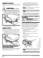
To examine the blades
CAUTION: Damaged or incorrectly
balanced blades can cause damage to
the product. Replace damaged blades.
Let an approved service agent help you
sharpen and balance blunt blades.
• Look at the blades to see if they are damaged
and if it is necessary to sharpen them.
To replace the blades
1. Remove the blade bolt.
2. Assemble the new blade with the side without
stamps in the direction of the cutting deck.
WARNING: Incorrect blade type
can cause objects to eject from the
cutting deck and cause serious
injury. Use only approved blades.
3. Attach the blade bolt. Torque the bolt to 61-75
Nm.
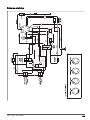
To remove the deck belt
Park the product on level ground and engage the
parking brake before you do this task.
1. Set the cutting deck in the lowest position.
2. Remove the 2 belt covers.
3. Remove dirt and unwanted materials from
around the cutter housings and the cutting deck
surface.
20 1741 - 001 - 08.11.2021
La page est en cours de chargement...
La page est en cours de chargement...
La page est en cours de chargement...
La page est en cours de chargement...
La page est en cours de chargement...
La page est en cours de chargement...
La page est en cours de chargement...
La page est en cours de chargement...
La page est en cours de chargement...
La page est en cours de chargement...
La page est en cours de chargement...
La page est en cours de chargement...
La page est en cours de chargement...
La page est en cours de chargement...
La page est en cours de chargement...
La page est en cours de chargement...
La page est en cours de chargement...
La page est en cours de chargement...
La page est en cours de chargement...
La page est en cours de chargement...
La page est en cours de chargement...
La page est en cours de chargement...
La page est en cours de chargement...
La page est en cours de chargement...
La page est en cours de chargement...
La page est en cours de chargement...
La page est en cours de chargement...
La page est en cours de chargement...
La page est en cours de chargement...
La page est en cours de chargement...
La page est en cours de chargement...
La page est en cours de chargement...
La page est en cours de chargement...
La page est en cours de chargement...
La page est en cours de chargement...
La page est en cours de chargement...
La page est en cours de chargement...
La page est en cours de chargement...
La page est en cours de chargement...
La page est en cours de chargement...
La page est en cours de chargement...
La page est en cours de chargement...
La page est en cours de chargement...
La page est en cours de chargement...
La page est en cours de chargement...
La page est en cours de chargement...
La page est en cours de chargement...
La page est en cours de chargement...
La page est en cours de chargement...
La page est en cours de chargement...
La page est en cours de chargement...
La page est en cours de chargement...
La page est en cours de chargement...
La page est en cours de chargement...
La page est en cours de chargement...
La page est en cours de chargement...
La page est en cours de chargement...
La page est en cours de chargement...
La page est en cours de chargement...
La page est en cours de chargement...
La page est en cours de chargement...
La page est en cours de chargement...
La page est en cours de chargement...
La page est en cours de chargement...
La page est en cours de chargement...
La page est en cours de chargement...
La page est en cours de chargement...
La page est en cours de chargement...
La page est en cours de chargement...
La page est en cours de chargement...
La page est en cours de chargement...
La page est en cours de chargement...
La page est en cours de chargement...
La page est en cours de chargement...
La page est en cours de chargement...
La page est en cours de chargement...
La page est en cours de chargement...
La page est en cours de chargement...
La page est en cours de chargement...
La page est en cours de chargement...
La page est en cours de chargement...
La page est en cours de chargement...
La page est en cours de chargement...
La page est en cours de chargement...
La page est en cours de chargement...
La page est en cours de chargement...
La page est en cours de chargement...
La page est en cours de chargement...
La page est en cours de chargement...
La page est en cours de chargement...
La page est en cours de chargement...
La page est en cours de chargement...
La page est en cours de chargement...
La page est en cours de chargement...
La page est en cours de chargement...
La page est en cours de chargement...
La page est en cours de chargement...
La page est en cours de chargement...
La page est en cours de chargement...
La page est en cours de chargement...
La page est en cours de chargement...
La page est en cours de chargement...
La page est en cours de chargement...
La page est en cours de chargement...
La page est en cours de chargement...
La page est en cours de chargement...
La page est en cours de chargement...
La page est en cours de chargement...
La page est en cours de chargement...
La page est en cours de chargement...
La page est en cours de chargement...
La page est en cours de chargement...
La page est en cours de chargement...
La page est en cours de chargement...
La page est en cours de chargement...
La page est en cours de chargement...
La page est en cours de chargement...
La page est en cours de chargement...
La page est en cours de chargement...
La page est en cours de chargement...
La page est en cours de chargement...
La page est en cours de chargement...
La page est en cours de chargement...
La page est en cours de chargement...
La page est en cours de chargement...
La page est en cours de chargement...
La page est en cours de chargement...
La page est en cours de chargement...
La page est en cours de chargement...
La page est en cours de chargement...
La page est en cours de chargement...
La page est en cours de chargement...
La page est en cours de chargement...
La page est en cours de chargement...
La page est en cours de chargement...
La page est en cours de chargement...
La page est en cours de chargement...
La page est en cours de chargement...
La page est en cours de chargement...
La page est en cours de chargement...
La page est en cours de chargement...
La page est en cours de chargement...
La page est en cours de chargement...
La page est en cours de chargement...
La page est en cours de chargement...
La page est en cours de chargement...
La page est en cours de chargement...
La page est en cours de chargement...
La page est en cours de chargement...
La page est en cours de chargement...
La page est en cours de chargement...
La page est en cours de chargement...
La page est en cours de chargement...
La page est en cours de chargement...
La page est en cours de chargement...
La page est en cours de chargement...
La page est en cours de chargement...
La page est en cours de chargement...
La page est en cours de chargement...
La page est en cours de chargement...
La page est en cours de chargement...
La page est en cours de chargement...
La page est en cours de chargement...
La page est en cours de chargement...
La page est en cours de chargement...
La page est en cours de chargement...
La page est en cours de chargement...
La page est en cours de chargement...
La page est en cours de chargement...
La page est en cours de chargement...
La page est en cours de chargement...
La page est en cours de chargement...
La page est en cours de chargement...
La page est en cours de chargement...
La page est en cours de chargement...
La page est en cours de chargement...
La page est en cours de chargement...
La page est en cours de chargement...
La page est en cours de chargement...
La page est en cours de chargement...
La page est en cours de chargement...
La page est en cours de chargement...
La page est en cours de chargement...
La page est en cours de chargement...
La page est en cours de chargement...
La page est en cours de chargement...
La page est en cours de chargement...
La page est en cours de chargement...
-
 1
1
-
 2
2
-
 3
3
-
 4
4
-
 5
5
-
 6
6
-
 7
7
-
 8
8
-
 9
9
-
 10
10
-
 11
11
-
 12
12
-
 13
13
-
 14
14
-
 15
15
-
 16
16
-
 17
17
-
 18
18
-
 19
19
-
 20
20
-
 21
21
-
 22
22
-
 23
23
-
 24
24
-
 25
25
-
 26
26
-
 27
27
-
 28
28
-
 29
29
-
 30
30
-
 31
31
-
 32
32
-
 33
33
-
 34
34
-
 35
35
-
 36
36
-
 37
37
-
 38
38
-
 39
39
-
 40
40
-
 41
41
-
 42
42
-
 43
43
-
 44
44
-
 45
45
-
 46
46
-
 47
47
-
 48
48
-
 49
49
-
 50
50
-
 51
51
-
 52
52
-
 53
53
-
 54
54
-
 55
55
-
 56
56
-
 57
57
-
 58
58
-
 59
59
-
 60
60
-
 61
61
-
 62
62
-
 63
63
-
 64
64
-
 65
65
-
 66
66
-
 67
67
-
 68
68
-
 69
69
-
 70
70
-
 71
71
-
 72
72
-
 73
73
-
 74
74
-
 75
75
-
 76
76
-
 77
77
-
 78
78
-
 79
79
-
 80
80
-
 81
81
-
 82
82
-
 83
83
-
 84
84
-
 85
85
-
 86
86
-
 87
87
-
 88
88
-
 89
89
-
 90
90
-
 91
91
-
 92
92
-
 93
93
-
 94
94
-
 95
95
-
 96
96
-
 97
97
-
 98
98
-
 99
99
-
 100
100
-
 101
101
-
 102
102
-
 103
103
-
 104
104
-
 105
105
-
 106
106
-
 107
107
-
 108
108
-
 109
109
-
 110
110
-
 111
111
-
 112
112
-
 113
113
-
 114
114
-
 115
115
-
 116
116
-
 117
117
-
 118
118
-
 119
119
-
 120
120
-
 121
121
-
 122
122
-
 123
123
-
 124
124
-
 125
125
-
 126
126
-
 127
127
-
 128
128
-
 129
129
-
 130
130
-
 131
131
-
 132
132
-
 133
133
-
 134
134
-
 135
135
-
 136
136
-
 137
137
-
 138
138
-
 139
139
-
 140
140
-
 141
141
-
 142
142
-
 143
143
-
 144
144
-
 145
145
-
 146
146
-
 147
147
-
 148
148
-
 149
149
-
 150
150
-
 151
151
-
 152
152
-
 153
153
-
 154
154
-
 155
155
-
 156
156
-
 157
157
-
 158
158
-
 159
159
-
 160
160
-
 161
161
-
 162
162
-
 163
163
-
 164
164
-
 165
165
-
 166
166
-
 167
167
-
 168
168
-
 169
169
-
 170
170
-
 171
171
-
 172
172
-
 173
173
-
 174
174
-
 175
175
-
 176
176
-
 177
177
-
 178
178
-
 179
179
-
 180
180
-
 181
181
-
 182
182
-
 183
183
-
 184
184
-
 185
185
-
 186
186
-
 187
187
-
 188
188
-
 189
189
-
 190
190
-
 191
191
-
 192
192
-
 193
193
-
 194
194
-
 195
195
-
 196
196
-
 197
197
-
 198
198
-
 199
199
-
 200
200
-
 201
201
-
 202
202
-
 203
203
-
 204
204
-
 205
205
-
 206
206
-
 207
207
-
 208
208


Husqvarna Z454XS Zero Turn Lawn Mower Manuel utilisateur
- Catégorie
- Tondeuses à gazon
- Taper
- Manuel utilisateur
dans d''autres langues
- italiano: Husqvarna Z454XS Zero Turn Lawn Mower Manuale utente
- English: Husqvarna Z454XS Zero Turn Lawn Mower User manual
- español: Husqvarna Z454XS Zero Turn Lawn Mower Manual de usuario
- Deutsch: Husqvarna Z454XS Zero Turn Lawn Mower Benutzerhandbuch
- Nederlands: Husqvarna Z454XS Zero Turn Lawn Mower Handleiding