
624

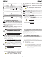
note - notes - note - notas - anmerkung - opmerkingen

1
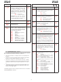
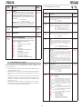
DICHIARAZIONE CE DI CONFORMITÁ
Fabbricante: GENIUS S.p.A.
Indirizzo: Via Pdre Elzi, 32 - 24050 - Grassobbio - Bregamo - ITALIAPdre Elzi, 32 - 24050 - Grassobbio - Bregamo - ITALIA - ITALIA
Dichiara che: L’apparecchiatura elettronica 624BLD
• è conforme ai requisiti essenziali di sicurezza delle seguenti direttive:
73/23/CEE e successiva modifica 93/68/CEE.
89/336/CEE e successiva modifica 92/31/CEE e 93/68/CEE
Nota aggiuntiva:
Questo prodotto è stato sottoposto a test in una configurazione tipica
omogenea (tutti prodotti di costruzione GENIUS S.p.A.).
Grassobbio, 01-09-2006
L’Amministratore Delegato
D. Gianantoni
1) ATTENZIONE! È importante per la sicurezza delle persone seguire attentamente
tutta l’istruzione. Una errata installazione o un errato uso del prodotto può
portare a gravi danni alle persone.
2) Leggere attentamente le istruzioni prima di iniziare l’installazione del prodot-
to.
3) I materiali dell’imballaggio (plastica, polistirolo, ecc.) non devono essere lasciati
alla portata dei bambini in quanto potenziali fonti di pericolo.
4) Conservare le istruzioni per riferimenti futuri.
5) Questo prodotto è stato progettato e costruito esclusivamente per l’utilizzo
indicato in questa documentazione. Qualsiasi altro utilizzo non espressamente
indicato potrebbe pregiudicare l’integrità del prodotto e/o rappresentare fonte
di pericolo.
6) GENIUS declina qualsiasi responsabilità derivata dall’uso improprio o diverso
da quello per cui l’automatismo è destinato.
7) Non installare l’apparecchio in atmosfera esplosiva: la presenza di gas o fumi
infiammabili costituisce un grave pericolo per la sicurezza.
8) Gli elementi costruttivi meccanici devono essere in accordo con quanto
stabilito dalle Norme EN 12604 e EN 12605.
Per i Paesi extra-CEE, oltre ai riferimenti normativi nazionali, per ottenere un livello
di sicurezza adeguato, devono essere seguite le Norme sopra riportate.
9) GENIUS non è responsabile dell’inosservanza della Buona Tecnica nella
costruzione delle chiusure da motorizzare, nonché delle deformazioni che
dovessero intervenire nell’utilizzo.
10) L’installazione deve essere effettuata nell’osservanza delle Norme EN 12453
e EN 12445.
Per i Paesi extra-CEE, oltre ai riferimenti normativi nazionali, per ottenere un livello
di sicurezza adeguato, devono essere seguite le Norme sopra riportate.
11) Prima di effettuare qualsiasi intervento sull’impianto, togliere l’alimentazione
elettrica.
12) Prevedere sulla rete di alimentazione dell’automazione un interruttore onnipolare
con distanza d’apertura dei contatti uguale o superiore a 3 mm. È consigliabile
l’uso di un magnetotermico da 6A con interruzione onnipolare.
13) Verificare che a monte dell’impianto vi sia un interruttore differenziale con
soglia da 0,03 A.
14) Verificare che l’impianto di terra sia realizzato a regola d’arte e collegarvi le
parti metalliche della chiusura.
15) I dispositivi di sicurezza (norma EN 12978) permettono di proteggere eventuali
aree di pericolo da Rischi meccanici di movimento, come ad Es. schiac-
ciamento, convogliamento, cesoiamento.
16) Per ogni impianto è consigliato l’utilizzo di almeno una segnalazione luminosa
(es: FAACLIGHT) nonché di un cartello di segnalazione fissato adeguatamente
sulla struttura dell’infisso, oltre ai dispositivi citati al punto “15”.
17) GENIUS declina ogni responsabilità ai fini della sicurezza e del buon funziona-
mento dell’automazione, in caso vengano utilizzati componenti dell’impianto
non di produzione GENIUS.
18) Per la manutenzione utilizzare esclusivamente parti originali GENIUS.
19) Non eseguire alcuna modifica sui componenti facenti parte del sistema
d’automazione.
20) L’installatore deve fornire tutte le informazioni relative al funzionamento ma-
nuale del sistema in caso di emergenza e consegnare all’Utente utilizzatore
dell’impianto il libretto d’avvertenze allegato al prodotto.
21) Non permettere ai bambini o persone di sostare nelle vicinanze del prodotto
durante il funzionamento.
22) Tenere fuori dalla portata dei bambini radiocomandi o qualsiasi altro datore
di impulso, per evitare che l’automazione possa essere azionata involonta-
riamente.
23) Il transito deve avvenire solo ad automazione ferma.
24) L’utente utilizzatore deve astenersi da qualsiasi tentativo di riparazione o
d’intervento e deve rivolgersi solo ed esclusivamente a personale qualificato
GENIUS o centri d’assistenza GENIUS.
25) Manutenzione: effettuare almeno semestralmente la verifica funzionale del-
l’impianto, con particolare attenzione all’efficienza dei dispositivi di sicurezza
(compresa, ove previsto, la forza di spinta dell’operatore) e di sblocco.
26) Tutto quello che non è previsto espressamente in queste istruzioni non è
permesso.
AVVERTENZE PER L’INSTALLATORE
OBBLIGHI GENERALI PER LA SICUREZZA

2
-
DL
F
+
LED
F2
J4
J5
J6
J3
J1
J2
J11C
J11B
J11A
J8
J9
F1
TF1
EMERG - DL5
STOP - DL4
FSW - DL3
CLOSE - DL2
OPEN - DL1
PIVOT - DL8
FCA - DL6
FCC - DL7
LOOP DETECTOR
1. AVVERTENZE
Attenzione: Prima di effettuare qualsiasi tipo di intervento sull’apparecchiatura elettronica (collegamenti, manutenzione) togliere sempre
l’alimentazione elettrica.
- Prevedere a monte dell’impianto un interruttore magnetotermico differenziale con adeguata soglia di intervento.
- Collegare il cavo di terra all’apposito morsetto previsto sul connettore J9 dell’apparecchiatura (vedi fig.2).
- Separare sempre i cavi di alimentazione da quelli di comando e di sicurezza (pulsante, ricevente, fotocellule, ecc.). Per evitare qualsiasi
disturbo elettrico utilizzare guaine separate o cavo schermato (con schermo collegato a massa).
APPARECCHIATURA ELETTRONICA 624
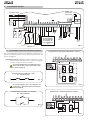
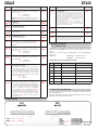
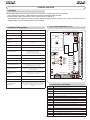
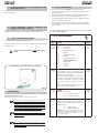
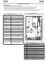
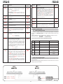
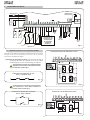
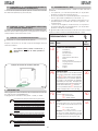
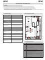
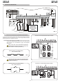
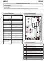
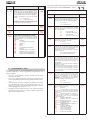
3. LAYOUT E COMPONENTI 624BLD
Tensione alimentazione 230 Vac (+6% -10%) - 50 Hz
Potenza assorbita 7 W
Carico max Motore 300 W
Alimentazione
accessori
24 Vdc
Corrente max accessori 500 mA
Temperatura ambiente -20°C ÷ +55°C
Fusibili di protezione F1 = F 5A - 250V F2 = T 0,8A - 250V
Logiche di
funzionamento
Automatica, Automatica1, Semiautomatica, Par-
cheggio, Parcheggio-Automatica, Condominiale,
Condominiale-Automatica,CITY, Uomo-presente,
Remote, Custom
Tempo di lavoro Programmabile (da 0 a 4 min)
Tempo di pausa Programmabile (da 0 a 4 min)
Forza motore Programmabile su 50 livelli
Ingressi in morsettiera Loop1, Loop2, Open, Close, Sicurezze in chiusura,
Stop, Emergenza, Alim. 230Vac + Terra
Ingressi in connettore
Finecorsa di apertura e chiusura, Detector, Con-
densatore motore,
Uscite in morsettiera Lampeggiatore, Ventola, Motore, Alimentazione
24Vdc, Fail-Safe, Uscita di Stato, Lampada spia
24Vdc, BUS
Connettore rapido
Innesto scheda ricevente a 5pin
Programmazione n° 3 tasti (+, -, F) e display
Funzioni programmabili Logiche, Tempo Pausa, Forza, Loop 1 e 2, Coppia
allo spunto, Prelampeggio, Chiusura lenta, Tempo
rallentamento, Tempo di lavoro, Uscita Lamp.
spia, Uscita Fail-safe, Uscita di stato, Uscita BUS,
Richiesta assistenza
2. CARATTERISTICHE TECNICHE
3.1 DESCRIZIONE COMPONENTI
DL DISPLAY DI SEGNALAZIONE E PROGRAMMAZIONE
LED LEDS DI CONTROLLO STATO INGRESSI
J1 MORSETTIERA BASSA TENSIONE
J2
MORSETTIERA COLLEGAMENTO MOTORE, LAMPEGGIA-
TORE E VENTOLA
J3 CONNETTORE FINECORSA DI APERTURA
J4
CONNETTORE RICEVENTE
J5 CONNETTORE FINECORSA DI CHIUSURA
J6 CONNETTORE SENSORE SFONDAMENTO ASTA
J8
CONNETTORE CONDENSATORE DI SPUNTO MOTORE
J9 MORSETTIERA ALIMENTAZIONE 230 VAC
J11 CONNETTORE LOOP DETECTOR ESTERNO
F1
FUSIBILE MOTORI E PRIMARIO TRASFORMATORE (F 5A)
F2 FUSIBILE BASSA TENSIONE E ACCESSORI (T 800mA)
F PULSANTE PROGRAMMAZIONE “F”
+ PULSANTE PROGRAMMAZIONE “+”
- PULSANTE PROGRAMMAZIONE “-”
TF1 TRASFORMATORE
Fig. 1

3
252321
LNPE
26242220
191816 17151412 1310 118 96 74 52 31
230Vac
50Hz
J1
J2
J8
J9
OPEN
CLOSE
STOP
EMERGENCY
230Vac
max 60W
24Vdc
3W
J6
J3
J5
FCC
FCA
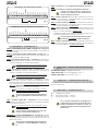
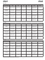
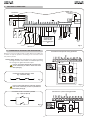
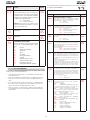
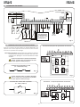
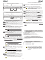
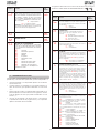
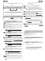
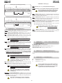
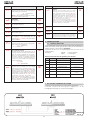
4. COLLEGAMENTI ELETTRICI
Per il collegamen-
to delle fotocellu-
le e dei dispositivi
di sicurezza, rife-
rirsi al paragrafo
4.1.
BLU
Prima di collegare le fotocellule (o altri dispositivi) è opportuno sce-
glierne il tipo di funzionamento in base alla zona di movimento che
devono proteggere:
Sicurezze in chiusura:
intervengono soltanto durante il movimento
di chiusura del la barriera, quindi sono adatte a proteggere
la zona di chiusura dal rischio di impatto.
Se occorre collegare due o più dispositivi di sicu-
rezza (contatti N.C.), questi vanno posti in serie
tra di loro (vedi fig.3).
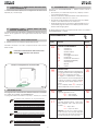
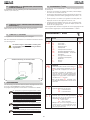
4.1. COLLEGAMENTO FOTOCELLULE E DISPOSITIVI DI SICUREZZA
CONDENSATORE
SPUNTO MOTORE
Collegamento 1 coppia di fotocellule in chiusura
Collegamento di due coppie di fotocellule in chiusura
Collegamento di 2 contatti N.A. in parallelo
(Es.: Open A, Open B)
Collegamento di 2 contatti N.C. in serie
(Es.: Fotocellule, Stop)
Se occorre collegare due o più dispositivi con
contatto N.A., questi vanno posti in parallelo tra
di loro (vedi fig.4).
VENTOLA
MOTORE
SFONDAMENTO SBARRA
Fig. 2
Fig. 5
Fig. 6
Fig. 4
Fig. 3

4
191816 17151412 1310 118 96 74 52 31
OPEN
A
STOP
LOOP
1
LOOP
2
LOOP
2
LOOP
1
CLOSE
FSW
EMERGENCY
OUT
1
OUT
2
OUT
4
OUT
3
GND
GND
GND
+24
V
+24
V
OUT
3
J1
191816 17151412 1310 118 96 74 52 31
OPEN
A
STOP
LOOP
1
LOOP
2
LOOP
2
LOOP
1
CLOSE
FSW
EMERGENCY
OUT
1
OUT
2
OUT
4
OUT
3
GND
GND
GND
+24
V
+24
V
OUT
3
J1
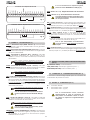
4.3. MORSETTIERA J2 - MOTORE, LAMPEGGIATORE E VENTOLA
(FIG. 2)
M (COM-MOT1-MOT2): Collegamento Motore
LAMP (LAMP-COM): Uscita lampeggiatore ( 230 V ~)
VENTOLA (FAN-COM): Uscita ventola ( 230 V ~)
4.5. MORSETTIERA J9 - ALIMENTAZIONE (FIG. 2)
PE : Collegamento di terra
N : Alimentazione 230 V~ ( Neutro )
L : Alimentazione 230 V~ ( Linea )
Per un corretto funzionamento è obbligatorio il
collegamento della scheda al conduttore di terra
presente nell’impianto. Prevedere a monte del
sistema un adeguato interruttore magnetotermico
differenziale.
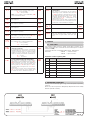
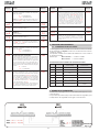
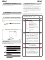
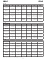
4.2. MORSETTIERA J1 - ACCESSORI (FIG. 2)
LOOP 1 - Alimentazione loop1 (OPEN - morsetti 1-2): collegare tra
questi morsetti il loop che si intende utilizzare come datore di
impulso OPEN.
LOOP 2 - Alimentazione loop2 (SAFETY/CLOSE - morsetti 3-4): col-
legare tra questi morsetti il loop che si intende utilizzare come
datore di impulso SAFETY/CLOSE.
OPEN - Comando di “Apertura” (N.A. - morsetto 5): si intende qual-
siasi datore d’impulso (es.: pulsante) che, chiudendo un contatto,
comanda l’apertura e/o chiusura della barriera.
Per installare più datori d’impulso d’apertura totale,
collegare i contatti N.A. in parallelo (vedi fig. 4).
CLOSE - Comando di “Chiusura” (N.A. - morsetto 6): si intende
qualsiasi datore d’impulso (es.: pulsante) che, chiudendo un
contatto, comanda la chiusura della barriera.
Per installare più datori d’impulso d’apertura totale,
collegare i contatti N.A. in parallelo (vedi fig. 4).
FSW - Contatto sicurezze in chiusura (N.C. - morsetto 7): il compito
delle sicurezze in chiusura è quello di salvaguardare la zona
interessata dal movimento della barriera durante la fase di chiu-
sura, invertendo il moto. Non intervengono mai durante il ciclo di
apertura. Le Sicurezze di chiusura, se impegnate ad automazione
aperta, impediscono il movimento di chiusura.
Per installare più dispositivi di sicurezze in chiusura
collegare i contatti N.C. in serie (fig. 3)
Se non vengono collegati dispositivi di sicurezza in
chiusura, ponticellare i morsetti FSW e OUT 1 (fig.
8).
STOP - Contatto di STOP (N.C. - morsetto 8): si intende qualsiasi
dispositivo (es.: pulsante) che aprendo un contatto può arrestare
il moto dell’automazione.
Per installare più dispositivi di STOP collegare i contatti
N.C. in serie (fig. 3).
Se non vengono collegati dispositivi di stop, pon-
ticellare i morsetti STOP e GND (fig. 8).
EMERGENCY - Contatto di EMERGENZA (N.C. - morsetto 9): si intende
qualsiasi interruttore che, azionato in emergenza, da luogo ad
una apertura della barriera
bloccandone il funzionamento fino al
ripristino del contatto.
Se non vengono collegati dispositivi di emergenza,
ponticellare i morsetti EMERGENCY e GND (fig.
8).
GND ( morsetti 10-11-19) - Negativo alimentazione accessori
24 Vdc ( morsetti 12-13)- Positivo alimentazione accessori
Il carico max. degli accessori è di 500 mA. Per
calcolare gli assorbimenti fare riferimento alle
istruzioni dei singoli accessori.
OUT 1 - Uscita 1 (morsetto 14): E’ possibile impostare l’uscita in una
delle funzioni descritte in Programmazione 2° Livello (vedi par.
5.2.). Il valore di default è FAILSAFE.
OUT 2 - Uscita 2 (morsetto 15): E’ possibile impostare l’uscita in una
delle funzioni descritte in Programmazione 2° Livello (vedi par.
5.2.). Il valore di default è sbarra CHIUSA.
OUT 3 - Uscita 3 (morsetto 16-17): E’ possibile impostare l’uscita in
una delle funzioni descritte in Programmazione 2° Livello (vedi
par. 5.2.). Il valore di default è LAMPADA SPIA.
Collegare a questi morsetti, seguendo le indicazioni di fig. 2, una
eventuale lampada spia a 24 Vdc - 3 W max.
Per non compromettere il corretto funzionamento
del sistema non superare la potenza indicata.
OUT 4 - Uscita 4 (morsetto 18): E’ possibile impostare l’uscita in una
delle funzioni descritte in Programmazione 2° Livello (vedi par.
5.2.). Il valore di default è ILLUMINAZIONE SBARRA.
4.4. CONNETTORE J8 - CONDENSATORE MOTORE (FIG. 2)
Connettore ad innesto rapido per il collegamento del condensatore
di spunto del motore.
Collegamento di un dispositivo di sicurezza
Collegamento di nessun dispositivo con contatto N.C.
Fig. 7
Fig. 8

5
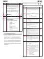
4.8. CONNETTORE J4 - INNESTO RAPIDO RICEVENTE
E’ utilizzato per la connessione rapida di Riceventi.
Innestare l’accessorio con il lato componenti rivolto verso l’interno
della scheda.
Inserimento e disinserimento delle schede vanno
effettuati SOLO dopo aver tolto tensione.
4.6. CONNETTORI J3, J5 - INNESTO RAPIDO FINECORSA APER-
TURA E CHIUSURA (FIG. 2)
Connettore ad innesto rapido per il collegamento dei finecorsa di
apertura (J3) e chiusura (J5).
4.7. CONNETTORE J11A,B,C - INNESTO RAPIDO PER LOOP
DETECTOR ESTERNO (FIG. 2)
Connettore ad innesto rapido per il collegamento del loop-detector
esterno. Per le regolazione e la programmazione riferirsi alla relativa
istruzione.
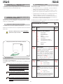
Esempio di collegamento di accessorio radio
la modifica dei parametri di programmazione
diventa immediatamente efficace, mentre la me-
morizzazione definitiva avviene solo all’uscita dalla
programmazione e ritorno alla visualizzazione dello
stato automazione. Se si toglie alimentazione all’ap-
parecchiatura prima del ritorno alla visualizzazione
dello stato, tutte le variazioni effettuate verranno
perse.
è possibile ritornare alla visualizzazione dello stato da
qualsiasi punto della programmazione di ogni livello
premendo contemporaneamente i tasti F e -.
Per ripristinare le impostazioni di default della pro-
grammazione premere contemporaneamente i
tasti +,- ed F e tenerli premuti per 5 secondi.
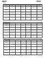
La tabella seguente indica la sequenza delle funzioni accessibili in
PROGRAMMAZIONE 1° LIVELLO:
5. PROGRAMMAZIONE
Per programmare il funzionamento dell’automazione è necessario
accedere alla modalità “PROGRAMMAZIONE”.
La programmazione si divide in tre parti: 1° LIVELLO, 2° LIVELLO.
5.1. PROGRAMMAZIONE 1° LIVELLO
L’accesso alla PROGRAMMAZIONE 1° LIVELLO avviene tramite il
pulsante F:
• premendolo (e mantenendolo premuto) il display mostra il
nome della prima funzione.
• rilasciando il pulsante, il display visualizza il valore della funzione
che può essere modificato con i tasti + e -.
• premendo nuovamente F (e mantenendolo premuto) il display
mostra il nome della funzione successiva, ecc.
• arrivati all’ultima funzione, la pressione del pulsante F provoca
l’uscita dalla programmazione ed il display riprende a visua-
lizzare lo stato degli ingressi.
Fig. 9
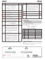
PROGRAMMAZIONE 1° LIVELLO
Display Funzione Default
LO
LOGICHE DI FUNZIONAMENTO
:
A
Automatica
A 1
Automatica 1
E
Semiautomatica
P
Parcheggio
PA
Parcheggio automatica
Cn
Condominio
CA
Condominio automatica
rb
City (logica per dissuasore)
C
Uomo presente
r
Remote
Cu
Custom
E
PA
TEMPO DI PAUSA:
Ha effetto solamente se è stata seleziona-
ta una logica automatica. Regolabile da
0
a
5 9
sec. a passi di un secondo.
In seguito la visualizzazione cambia in
minuti e decine di secondi (separati da
un punto) e il tempo si regola a passi di
10 secondi, fino al valore massimo di
4 . 1
minuti.
ES: se il display indica
2.5
, il tempo di
pausa corrisponde a 2 min. e 50 sec.
20
FO
FORZA:
regola la spinta del motore.
0 1
= forza minima
50
= forza massima
50
L 1
LOOP 1:
Attivando questa funzione, il loop colle-
gato all’ingresso Loop1 avrà la funzione
di OPEN.
Y
= loop1 attivo
n o
= loop1 non attivo
Attenzione: nel caso non si attivi la funzione,
lo stato del Loop1 sarà comunque disponibile
su una delle uscite opportunamente impostata
(vedi programmazione di secondo livello).
no

6
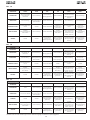
PROGRAMMAZIONE 2° LIVELLO
Display Funzione Default
bo
COPPIA MASSIMA ALLO SPUNTO
:
il motore lavora a coppia massima (igno-
rando la regolazione di coppia) nell’istan-
te iniziale del movimento.
Y
= Attiva
no = Esclusa
Y
PF
PRELAMPEGGIO:
permette di attivare il lampeggiatore per
5 sec prima dell’inizio del movimento.
no
escluso
OC prima di ogni movimento
CL
prima della chiusura
PA
solo a fina pausa
no
SC
CHIUSURA LENTA:
permette di impostare tutta la fase di
chiusura a velocità rallentata.
Y
= Attiva
n
o
= Esclusa
no
tr
TEMPO RALLENTAMENTO A FINECORSA:
permette di impostare il tempo (in secondi)
di rallentamento dopo l’intervento dei fine-
corsa di apertura e di chiusura.
Regolabile da 0 a 10 sec. a passi di un
secondo.
0 0 = rallentamento escluso
1 0 = rallentamento massimo
03
t
TEMPO DI LAVORO (time-out):
E’ opportuno impostare un valorie di 5÷10
secondi superiore al tempo neccessario al-
l’automazione per andare dalla posizione di
chiusura a quella di apertura e viceversa.
Regolabile da 0 a 59 sec. a passi di un
secondo.
In seguito la visualizzazione cambia in
minuti e decine di secondi (separati da
un punto) e il tempo si regola a passi di
10 secondi, fino al valore massimo di 4.1
minuti.
20
FS
FAIL SAFE:
L’attivazione della funzione abilita un test
di funzionamento delle fotocellule prima
di ogni movimento dell’automazione, in-
dipendentemente dall’uscita utilizzata.
Se il test fallisce l’automazione non inizia
il movimento.
Y
= Attiva
no
= Esclusa
no
o 1
USCITA 1:
E’ possibile impostare l’uscita in una delle
seguenti funzioni:
00 FAILSAFE
0 1 LAMPADA SPIA (accesa in aper-
tura e pausa, lampeggiante in chiusura,
spenta ad automazione chiusa).
02 ILLUMINAZIONE SBARRA (uscita
attiva con sbarra chiusa e in pausa, inatti-
va con asta aperta, intermittente in movi-
mento)
03 sbarra CHIUSA
04 sbarra APERTA o in PAUSA, si spe-
gne durante il prelampeggio chiusura.
05 sbarra in MOVIMENTO APERTURA,
compreso prelampeggio.
06 sbarra in MOVIMENTO CHIUSURA,
compreso prelampeggio.
07 sbarra FERMA
08 sbarra in EMERGENZA
09 LOOP1 impegnato
10 LOOP2 impegnato
1 1 OPEN per 624 SLAVE
12 CLOSE per 624 SLAVE
00
Display Funzione Default
L 2
LOOP 2:
Attivando questa funzione, il loop
collegato all’ingresso Loop2 avrà
la funzione di SAFETY / CLOSE,
ovvero funzionerà come SAFETY
durante la fase di chiusura e al
disimpegno comanderà il CLOSE
alla scheda.
Y
= loop2 attivo
n o
= loop2 non attivo
Attenzione: nel caso non si attivi la
funzione, lo stato del Loop2 sarà co-
munque disponibile su una delle usci-
te opportunamente impostata.
no
S 1
NESSUN EFFETTO
05
S2
NESSUN EFFETTO
05
S t
STATO DELL’AUTOMAZIONE:
Uscita dalla programmazione,
memorizzazione dei dati imposta-
ti e ritorno alla visualizzazione dello
stato dell’automazione.
00
Chiuso
0 1
Prelampeggio apertura
02
Apertura
03
Aperto
04
In pausa
05
Prelampeggio chiusura
06
Chiusura
07
Fermo pronto a chiudere
08
Fermo pronto ad aprire
09
Apertura d’emergenza
10
Intervento sicurezza chiusura
5.2. PROGRAMMAZIONE 2° LIVELLO
Per accedere alla PROGRAMMAZIONE 2° LIVELLO premere il pulsante
F e, mantenendolo premuto, premere il pulsante +:
• rilasciando il pulsante + il display mostra il nome della prima
funzione.
• rilasciando anche il pulsante F, il display visualizza il valore della
funzione che può essere modificato con i tasti + e -.
• premendo il tasto F (e mantenendolo premuto) il display
mostra il nome della funzione successiva, rilasciandolo viene
visualizzato il valore che può essere modificato con i tasti +
e -.
• arrivati all’ultima funzione, la pressione del pulsante F provoca
l’uscita dalla programmazione ed il display riprende a visua-
lizzare lo stato degli ingressi.
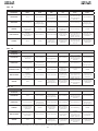
La tabella seguente indica la sequenza delle funzioni accessibili in
PROGRAMMAZIONE 2° LIVELLO:

7
Display Funzione Default
n C
PROGRAMMAZIONE CICLI IN CENTINAIA
DI MIGLIAIA:
Permette di impostare un conto alla ro-
vescia dei cicli di funzionamento dell’im-
pianto, valore impostabile da 0 a 99
(centinaia di migliaia di cicli). Il valore vi-
sualizzato si aggiorna con il susseguirsi dei
cicli, interagendo con il valore di n c. (1
decremento di n C corrisponde a 99
decrementi di n c).
La funzione può essesere utilizzata, in
combinazione con nc , per verificare
l’uso dell’impianto e per usufruire della
“Richiesta di assistenza”.
01
h 1
NESSUN EFFETTO
oo
h 2
NESSUN EFFETTO
oo
S t
STATO DELL’AUTOMAZIONE:
Uscita dalla programmazione, memoriz-
zazione dei dati e ritorno alla visualizzazio-
ne dello stato cancello (vedi par. 5.1.).
Display Funzione Default
P 1
POLARITà USCITA 1:
permette di configurare lo stato della po-
larità d’uscita.
Y
= polarità N.C.
n
o
= polarità N.O.
Nota: se l’uscita è impostata come FAIL-
SAFE (
00
) lasciare il valore di default.
no
o 2
USCITA 2:
Vedi uscita 1
03
P 2
POLARITà USCITA 2:
Vedi polarità uscita 1
no
o 3
USCITA 3:
Vedi uscita 1
0 1
P 3
POLARITà USCITA 3:
Vedi polarità uscita 1
no
o 4
USCITA 4:
Vedi uscita 1, eccetto alle funzioni
00,
1 1 , 12
che in questo caso non hanno
effetto.
02
P 4
POLARITà USCITA 4:
permette di configurare lo stato della po-
larità d’uscita.
Y
= polarità N.C.
n
o
= polarità N.O.
no
P 4
POLARITà USCITA 4:
permette di configurare lo stato della po-
larità d’uscita.
Y
= polarità N.C.
n
o
= polarità N.O.
no
A S
RICHIESTA ASSISTENZA (abbinata alle due
funzioni successive):
Se attivata, al termine del conto alla ro-
vescia (impostabile con le due funzione
successive “Programmazione cicli”) attiva
l’uscita LAMP per un periodo di 4 sec ogni
30 sec (richiesta intervento). Può essere
utile per impostare interventi di manuten-
zione programmata.
Y
= Attiva
no
= Esclusa
no
n c
PROGRAMMAZIONE CICLI IN MIGLIAIA:
Permette di impostare un conto alla rove-
scia dei cicli di funzionamento dell’impian-
to, valore impostabile da
0
a
99
(migliaia
di cicli). Il valore visualizzato si aggiorna
con il susseguirsi dei cicli, interagendo
con il valore di
n C
(99 decrementi di
n c
corrispondono a un decremento di
n C
).
La funzione può essere utilizzata, in combi-
nazione con
n C
, per verificare l’uso del-
l’impianto e per usufruire della “Richiesta
di assistenza”.
00
6. MESSA IN FUNZIONE
6.1. VERIFICA DEI LED
La tabella sottostante riporta lo stato dei leds in relazione allo stato
degli ingressi (in neretto la condizione di automazione chiusa a
riposo).
Verificare lo stato dei leds di segnalazione come dalla tabella
seguente
Notare che: Led acceso = contatto chiuso
Led spento = contatto aperto
7. PROVA DELL’AUTOMAZIONE
Al termine della programmazione, controllare il corretto funziona-
mento dell’impianto.
Verificare soprattutto l’adeguata regolazione della forza e il corretto
intervento dei dispositivi di sicurezza.
LED Descrizione ACCESO (contatto chiuso) SPENTO (contatto aperto)
DL1 OPEN Comando attivo Comando inattivo
DL2 CLOSE Comando attivo Comando inattivo
DL3 FSW Sicurezze disimpegnate Sicurezze impegnate
DL4 STOP Comando inattivo Comando attivo
DL5 EMERGENCY Comando inattivo Comando attivo
DL6 FCA Finecorsa apertura libero Finecorsa apertura impegnato
DL7 FCC Finecorsa chiusura libero Finecorsa chiusura impegnato
Funzionamento leds di segnalazione stato
Fig. 10
8. MASTER-SLAVE

8
Tab. 1/b
Tab. 1/a
Tab. 1/c
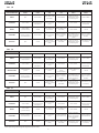
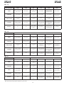
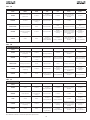
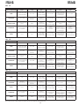
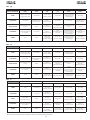
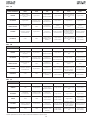
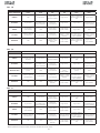
LOGICA “A” IMPULSI
STATO AUTOMAZIONE OPEN A CLOSE STOP FSW LOOP 1 LOOP 2
CHIUSO
apre e richiude dopo il
tempo pausa
nessun effetto
nessun effetto (aper-
tura inibita)
nessun effetto
apre e al termine
dell’apertura chiude
se disimpegnato
nessun effetto
IN APERTURA nessun effetto
inverte in chiusura
immediatamente
blocca il funziona-
mento
nessun effetto nessun effetto nessun effetto
APERTO IN PAUSA
ricarica il tempo
pausa
chiude
blocca il funziona-
mento
ricarica il tempo
pausa
(chiusura inibita)
ricarica il tempo
pausa
ricarica il tempo
pausa
(chiusura inibita)
IN CHIUSURA
inverte in apertura
immediatamente
nessun effetto
blocca il funziona-
mento
inverte in apertura
immediatamente
inverte in apertura
immediatamente e al
termine dell’apertura
chiude se disimpe-
gnato
inverte in apertura
immediatamente
BLOCCATO chiude chiude
nessun effetto
(apertura e chiusura
inibite)
nessun effetto (chiu-
sura inibita)
apre e al termine
dell’apertura chiude
se disimpegnato
nessun effetto (chiu-
sura inibita)
LOGICA “A1” IMPULSI
STATO AUTOMAZIONE OPEN A CLOSE STOP FSW LOOP 1 LOOP 2
CHIUSO
apre e richiude dopo il
tempo pausa
nessun effetto
nessun effetto (aper-
tura inibita)
nessun effetto
apre e al termine
dell’apertura chiude
se disimpegnato
nessun effetto
IN APERTURA nessun effetto
inverte in chiusura
immediatamente
blocca il funziona-
mento
chiude immedia-
tamente al termine
dell’apertura
nessun effetto
chiude immedia-
tamente al termine
dell’apertura
APERTO IN PAUSA
ricarica il tempo
pausa
chiude
blocca il funziona-
mento
chiude
ricarica il tempo
pausa
chiude
IN CHIUSURA
inverte in apertura
immediatamente
nessun effetto
blocca il funziona-
mento
inverte in apertura
immediatamente
inverte in apertura
immediatamente e al
termine dell’apertura
chiude se disimpe-
gnato
inverte in apertura
immediatamente
BLOCCATO chiude chiude
nessun effetto
(apertura e chiusura
inibite)
nessun effetto (chiu-
sura inibita)
apre e al termine
dell’apertura chiude
se disimpegnato
nessun effetto (chiu-
sura inibita)
LOGICA “E” IMPULSI
STATO AUTOMAZIONE OPEN A CLOSE STOP FSW LOOP 1 LOOP 2
CHIUSO apre nessun effetto
nessun effetto (aper-
tura inibita)
nessun effetto
apre e al termine
dell’apertura chiude
se disimpegnato
nessun effetto
IN APERTURA
blocca il funziona-
mento
inverte in chiusura
immediatamente
blocca il funziona-
mento
nessun effetto nessun effetto nessun effetto
APERTO chiude chiude
nessun effetto (chiu-
sura inibita)
nessun effetto (chiu-
sura inibita)
nessun effetto
nessun effetto (chiu-
sura inibita)
IN CHIUSURA
inverte in apertura
immediatamente
nessun effetto
blocca il funziona-
mento
inverte in apertura
immediatamente
inverte in apertura
immediatamente e al
termine dell’apertura
chiude se disimpe-
gnato
inverte in apertura
immediatamente
BLOCCATO chiude chiude
nessun effetto
(apertura e chiusura
inibite)
nessun effetto (chiu-
sura inibita)
apre e al termine
dell’apertura chiude
se disimpegnato
nessun effetto (chiu-
sura inibita)
Tra parentesi gli effetti sugli altri ingressi a impulso attivo

9
Tab. 1/d
Tab. 1/e
Tab. 1/f
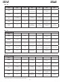
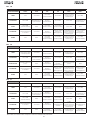
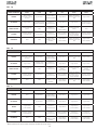
LOGICA “P” IMPULSI
STATO AUTOMAZIONE OPEN A CLOSE STOP FSW LOOP 1 LOOP 2
CHIUSO apre nessun effetto
nessun effetto (aper-
tura inibita)
nessun effetto
apre e al termine
dell’apertura chiude
se disimpegnato
nessun effetto
IN APERTURA nessun effetto
chiude immedia-
tamente al termine
dell’apertura
blocca il funziona-
mento
nessun effetto nessun effetto
chiude immedia-
tamente al termine
dell’apertura
APERTO
nessun effetto
(chiusura inibita)
chiude
nessun effetto (chiu-
sura inibita)
nessun effetto (chiu-
sura inibita)
nessun effetto chiude
IN CHIUSURA
inverte in apertura
immediatamente
nessun effetto
blocca il funziona-
mento
blocca e al disim-
pegno continua a
chiudere
inverte in apertura
immediatamente e al
termine dell’apertura
chiude se disimpe-
gnato
blocca e al disim-
pegno continua a
chiudere
BLOCCATO apre chiude
nessun effetto
(apertura e chiusura
inibite)
nessun effetto (chiu-
sura inibita)
apre e al termine
dell’apertura chiude
se disimpegnato
nessun effetto (chiu-
sura inibita)
Tra parentesi gli effetti sugli altri ingressi a impulso attivo
LOGICA “PA” IMPULSI
STATO AUTOMAZIONE OPEN A CLOSE STOP FSW LOOP 1 LOOP 2
CHIUSO
apre e richiude dopo il
tempo pausa
nessun effetto
nessun effetto (aper-
tura inibita)
nessun effetto
apre e al termine
dell’apertura chiude
se disimpegnato
nessun effetto
IN APERTURA nessun effetto
chiude immedia-
tamente al termine
dell’apertura
blocca il funziona-
mento
nessun effetto nessun effetto
chiude immedia-
tamente al termine
dell’apertura
APERTO IN PAUSA
ricarica il tempo
pausa
chiude
blocca il funziona-
mento
ricarica il tempo
pausa
(chiusura inibita)
ricarica il tempo di
pausa
chiude
IN CHIUSURA
inverte in apertura
immediatamente
nessun effetto
blocca il funziona-
mento
blocca e al disim-
pegno continua a
chiudere
inverte in apertura
immediatamente e al
termine dell’apertura
chiude se disimpe-
gnato
blocca e al disim-
pegno continua a
chiudere
BLOCCATO apre chiude
nessun effetto
(apertura e chiusura
inibite)
nessun effetto (chiu-
sura inibita)
apre e al termine
dell’apertura chiude
se disimpegnato
nessun effetto (chiu-
sura inibita)
LOGICA “Cn” IMPULSI
STATO AUTOMAZIONE OPEN A CLOSE STOP FSW LOOP 1 LOOP 2
CHIUSO apre nessun effetto
nessun effetto (aper-
tura inibita)
nessun effetto
apre e al termine
dell’apertura chiude
se disimpegnato
nessun effetto
IN APERTURA nessun effetto
chiude immedia-
tamente al termine
dell’apertura
blocca il funziona-
mento
nessun effetto nessun effetto
chiude immedia-
tamente al termine
dell’apertura
APERTO
nessun effetto
(chiusura inibita)
chiude
nessun effetto (chiu-
sura inibita)
nessun effetto (chiu-
sura inibita)
nessun effetto chiude
IN CHIUSURA
inverte in apertura
immediatamente
nessun effetto
blocca il funziona-
mento
inverte in apertura
immediatamente
inverte in apertura
immediatamente e al
termine dell’apertura
chiude se disimpe-
gnato
inverte in apertura
immediatamente
BLOCCATO apre chiude
nessun effetto
(apertura e chiusura
inibite)
nessun effetto (chiu-
sura inibita)
apre e al termine
dell’apertura chiude
se disimpegnato
nessun effetto (chiu-
sura inibita)

10
Tab. 1/i
Tab. 1/g
Tab. 1/h
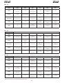
LOGICA “CA” IMPULSI
STATO AUTOMAZIONE OPEN A CLOSE STOP FSW LOOP 1 LOOP 2
CHIUSO
apre e richiude dopo il
tempo pausa
nessun effetto
nessun effetto (aper-
tura inibita)
nessun effetto
apre e al termine
dell’apertura chiude
se disimpegnato
nessun effetto
IN APERTURA nessun effetto
chiude immedia-
tamente al termine
dell’apertura
blocca il funziona-
mento
nessun effetto nessun effetto
chiude immedia-
tamente al termine
dell’apertura
APERTO IN PAUSA
ricarica il tempo
pausa
chiude
blocca il funziona-
mento
ricarica il tempo
pausa
(chiusura inibita)
ricarica il tempo di
pausa
chiude
IN CHIUSURA
inverte in apertura
immediatamente
nessun effetto
blocca il funziona-
mento
inverte in apertura
immediatamente
inverte in apertura
immediatamente e al
termine dell’apertura
chiude se disimpe-
gnato
inverte in apertura
immediatamente
BLOCCATO apre chiude
nessun effetto
(apertura e chiusura
inibite)
nessun effetto (chiu-
sura inibita)
apre e al termine
dell’apertura chiude
se disimpegnato
nessun effetto (chiu-
sura inibita)
LOGICA “rb” IMPULSI
STATO AUTOMAZIONE OPEN A CLOSE STOP FSW LOOP 1 LOOP 2
CHIUSO
apre e richiude dopo il
tempo pausa
nessun effetto
nessun effetto (aper-
tura inibita)
nessun effetto
apre e al termine
dell’apertura chiude
se disimpegnato
nessun effetto
IN APERTURA nessun effetto
inverte in chiusura
immediatamente
blocca il funziona-
mento
nessun effetto nessun effetto nessun effetto
APERTO IN PAUSA
ricarica il tempo
pausa
chiude
blocca il funziona-
mento
ricarica il tempo
pausa
(chiusura inibita)
ricarica il tempo di
pausa
ricarica il tempo
pausa
(chiusura inibita)
IN CHIUSURA
inverte in apertura
immediatamente
nessun effetto
blocca il funziona-
mento
inverte in apertura
immediatamente
inverte in apertura
immediatamente e al
termine dell’apertura
chiude se disimpe-
gnato
inverte in apertura
immediatamente
BLOCCATO apre chiude
nessun effetto
(apertura e chiusura
inibite)
nessun effetto (chiu-
sura inibita)
apre e al termine
dell’apertura chiude
se disimpegnato
nessun effetto (chiu-
sura inibita)
Tra parentesi gli effetti sugli altri ingressi a impulso attivo
LOGICA “C”
COMANDI MANTENUTI
IMPULSI
STATO AUTOMAZIONE OPEN A CLOSE STOP FSW LOOP 1 LOOP 2
CHIUSO apre nessun effetto
nessun effetto (aper-
tura inibita)
nessun effetto nessun effetto nessun effetto
IN APERTURA / nessun effetto
blocca il funziona-
mento
nessun effetto nessun effetto nessun effetto
APERTO
nessun effetto
(chiusura inibita)
chiude
blocca il funziona-
mento
nessun effetto
nessun effetto
(chiusura inibita)
nessun effetto
(chiusura inibita)
IN CHIUSURA
inverte in apertura
immediatamente
/
blocca il funziona-
mento
inverte in apertura
immediatamente
blocca il funziona-
mento
blocca il funziona-
mento
BLOCCATO apre chiude
nessun effetto
(apertura e chiusura
inibite)
nessun effetto (chiu-
sura inibita)
nessun effetto
(chiusura inibita)
nessun effetto
(chiusura inibita)

11
CE DECLARATION OF CONFORMITY
Manufacturer: GENIUS S.p.A.
Address: Via Pdre Elzi, 32 - 24050 - Grassobbio - Bregamo - ITALYPdre Elzi, 32 - 24050 - Grassobbio - Bregamo - ITALY - ITALY
Declares that: 624BLD control board,
• conforms to the essential safety requirements of the following directives:
73/23/CEE and subsequent amendment 93/68/CEE.
89/336/CEE and subsequent amendment 92/31/CEE and 93/68/CEE
Additional note:
This product underwent tests in a typical uniform configuration
(all products manufactured by GENIUS S.p.A.).
Grassobbio, 01-09-2006
The Managing Director
D. Gianantoni
1) ATTENTION! To ensure the safety of people, it is important that you read
all the following instructions. Incorrect installation or incorrect use of the
product could cause serious harm to people.
2) Carefully read the instructions before beginning to install the product.
3) Do not leave packing materials (plastic, polystyrene, etc.) within reach of
children as such materials are potential sources of danger.
4) Store these instructions for future reference.
5) This product was designed and built strictly for the use indicated in this
documentation. Any other use, not expressly indicated here, could
compromise the good condition/operation of the product and/or be a
source of danger.
6) GENIUS declines all liability caused by improper use or use other than that
for which the automated system was intended.
7) Do not install the equipment in an explosive atmosphere: the presence of
inflammable gas or fumes is a serious danger to safety.
8) The mechanical parts must conform to the provisions of Standards EN 12604
and EN 12605.
For non-EU countries, to obtain an adequate level of safety, the Standards
mentioned above must be observed, in addition to national legal
regulations.
9) GENIUS is not responsible for failure to observe Good Technique in the
construction of the closing elements to be motorised, or for any deformation
that may occur during use.
10) The installation must conform to Standards EN 12453 and EN 12445.
For non-EU countries, to obtain an adequate level of safety, the Standards
mentioned above must be observed, in addition to national legal
regulations.
11) Before attempting any job on the system, cut out electrical power .
12) The mains power supply of the automated system must be fitted with an
all-pole switch with contact opening distance of 3mm or greater. Use of a
6A thermal breaker with all-pole circuit break is recommended.
13) Make sure that a differential switch with threshold of 0.03 A is fitted upstream
of the system.
14) Make sure that the earthing system is perfectly constructed, and connect
metal parts of the means of the closure to it.
15) The safety devices (EN 12978 standard) protect any danger areas against
mechanical movement Risks, such as crushing, dragging, and shearing.
16) Use of at least one indicator-light (e.g. FAACLIGHT ) is recommended for every
system, as well as a warning sign adequately secured to the frame structure,
in addition to the devices mentioned at point “15”.
17) GENIUS declines all liability as concerns safety and efficient operation of
the automated system, if system components not produced by GENIUS are
used.
18) For maintenance, strictly use original parts by GENIUS.
19) Do not in any way modify the components of the automated system.
20) The installer shall supply all information concerning manual operation of
the system in case of an emergency, and shall hand over to the user the
warnings handbook supplied with the product.
21) Do not allow children or adults to stay near the product while it is
operating.
22) Keep remote controls or other pulse generators away from children, to prevent
the automated system from being activated involuntarily.
23) Transit is permitted only when the automated system is idle.
24) The User must not in any way attempt to repair or to take direct action and
must solely contact qualified GENIUS personnel or GENIUS service centres.
25) Maintenance: check at least every 6 months the efficiency of the system, particularly
the efficiency of the safety devices (including, where foreseen, the operator thrust
force) and of the release devices.
26) Anything not expressly specified in these instructions is not permitted.
WARNINGS FOR THE INSTALLER
GENERAL SAFETY OBLIGATIONS

12
-
DL
F
+
LED
F2
J4
J5
J6
J3
J1
J2
J11C
J11B
J11A
J8
J9
F1
TF1
EMERG - DL5
STOP - DL4
FSW - DL3
CLOSE - DL2
OPEN - DL1
PIVOT - DL8
FCA - DL6
FCC - DL7
LOOP DETECTOR
1. WARNINGS
Attention: Before attempting any work on the control unit (connections, maintenance), always turn off power.
- Install, upstream of the system, a differential thermal breaker with adequate tripping threshold.
- Connect the earth cable to the terminal on the J9 connector of the unit (see fig. 2).
- Always separate power cables from control and safety cables (push-button, receiver, photocells, etc.). To avoid any electrical noise, use
separate sheaths or a screened cable (with the screen earthed).
CONTROL UNIT 624
3. LAYOUT AND COMPONENTS of 624
Power supply voltage
230 Vac (+6% -10%) - 50 Hz
Absorbed power
7 W
Motor max. load
300 W
Power supply for ac-
cessories
24 Vdc
Accessories max.
current
500 mA
Ambient temperature
-20°C - +55°C
Fuses
F1 = F 5A - 250V F2 = T 0.8A - 250V
Function logics
Automatic, Automatic 1, Semiautomatic,
Parking, Parking-Automatic,
Condo, Condo-automatic
CITY, Dead-man, Remote, Custom
Work time
Programmable (from 0 to 4 minutes)
Pause time
Programmable (from 0 to 4 minutes)
Motor power
Programmable on 50 levels
Terminal board inputs
Loop1, Loop2, Open, Close,
Closing safety devices, Stop, Emergency,
Power supply 230Vac + Earth
Connector inputs
Opening and closing limit-switch, Detector
Motor capacitor.
Terminal board
outputs
Flashing light, Fan, Motor,
Power supply 24 Vdc, Fail-safe, Status output,
Indicator light 24 Vdc, BUS
Rapid connector
5-pin receiver
Programming
No. 3 keys (+, -, F) and display
Programmable
functions
Logics, Pause Time, Power, Loop 1 and 2, Thrust
torque, Pre-flashing, Slow closure, Deceleration
time, Work time, Indicator light output, Fail-safe
output, Status output, BUS output, Assistance
request
2. TECHNICAL SPECIFICATIONS
3.1 DESCRIPTION OF COMPONENTS
DL SIGNALS AND PROGRAMMING DISPLAY
LED INPUT STATUS CONTROL LEDs
J1 LOW-VOLTAGE TERMINAL BOARD
J2
TERMINAL BOARD FOR CONNECTION OF MOTOR,
FLASHING LIGHT AND FAN
J3 OPENING LIMIT-SWITCH CONNECTOR
J4 CONNECTOR RECEIVER
J5 CLOSING LIMIT-SWITCH CONNECTOR
J6 CONNECTOR FOR ROD BREAKING SENSOR
J8 CONNECTOR FOR MOTOR THRUST CAPACITOR
J9 TERMINAL-BOARD FOR 230 VAC POWER SUPPLY
J11 CONNECTOR EXTERNAL LOOP DETECTOR
F1
FUSE FOR MOTORS AND TRANSFORMER PRIMARY
WINDING (F 5A)
F2
FUSE FOR LOW VOLTAGE AND ACCESSORIES (T 800mA)
F PROGRAMMING PUSH-BUTTON ”F”
+ PROGRAMMING PUSH-BUTTON ”+”
- PROGRAMMING PUSH-BUTTON ”-”
TF1 TRANSFORMER
Fig. 1

13
252321
LNPE
26242220
191816 17151412 1310 118 96 74 52 31
230Vac
50Hz
J1
J2
J8
J9
OPEN
CLOSE
STOP
EMERGENCY
230Vac
max 60W
24Vdc
3W
J6
J3
J5
FCC
FCA
4. ELECTRICAL CONNECTIONS
To connect the
photocells and
safety devices,
consult paragraph
4.1.
BLUE
Before you connect the photocells (or other devices) we advise you
to select the type of operation according to the movement zone
they have to protect.
Closing safety devices:
they are tripped only during the barrier
closing movement, and, therefore, are suitable for protecting
the closing zone against the risk of impact.
If two or more safety devices (NC contacts) have
to be connected, put them in series with each
other (see fig.3).
4.1. CONNECTION OF PHOTOCELLS AND SAFETY DEVICES
MOTOR THRUST
CAPACITOR
Connection of 1 pair of closing photocells
Connection of two pairs of closing photocells
Connection of 2 N.O. contacts in parallel
(E.g.: Open A, Open B)
Connection of 2 NC contacts in series
(E.g.: Photocells, Stop)
If two or more safety devices with N.O. contacts
have to be connected, put them in parallel with
each other (see fig.4).
FAN
MOTOR
BEAM BREAKING
Fig. 2
Fig. 5
Fig. 6
Fig. 4
Fig. 3

14
191816 17151412 1310 118 96 74 52 31
OPEN
A
STOP
LOOP
1
LOOP
2
LOOP
2
LOOP
1
CLOSE
FSW
EMERGENCY
OUT
1
OUT
2
OUT
4
OUT
3
GND
GND
GND
+24
V
+24
V
OUT
3
J1
191816 17151412 1310 118 96 74 52 31
OPEN
A
STOP
LOOP
1
LOOP
2
LOOP
2
LOOP
1
CLOSE
FSW
EMERGENCY
OUT
1
OUT
2
OUT
4
OUT
3
GND
GND
GND
+24
V
+24
V
OUT
3
J1
4.2. J1 TERMINAL-BOARD - ACCESSORIES (FIG.2)
LOOP 1 - Power supply to loop1 (OPEN - terminals 1-2): use these
terminals to connect the loop you wish to use as an OPEN pulse
generator.
LOOP 2 - Power supply to loop2 (SAFETY/CLOSE - terminals 3-4):
connect between these terminals the loop you wish to use as a
SAFETY/CLOSE pulse generator.
OPEN - “Opening” Command (N.O. - terminal 5): this refers to any
pulse generator (e.g.: push-button) which, by closing a contact,
commands the barrier to open and/or close.
To install several total opening pulse generators,
connect the N.O. contacts in parallel (see fig. 4)
CLOSE - “Closing” Command (N.O. - terminal 6): this refers to any
pulse generator (e.g.: push-button) which, by closing a contact,
commands the barrier to close.
To install several total opening pulse generators,
connect the N.O. contacts in parallel (see fig. 4)
FSW - Closing safety-devices contact (N.C. -. terminal 7) The purpose
of the closing safety devices is to protect the barrier movement
area during closure, by reversing motion. They are never tripped
during the opening cycle. If the closing safety devices are
engaged when the automated system is in open status, they
prevent the closing movement.
To install several closing safety devices, connect the
N.C. contacts in series(fig. 3).
If closing safety devices are not connected, jumper
connect the FSW and FAIL SAFE terminals (fig. 8).
STOP - STOP contact (N.C. - terminal 8): this refers to any device
(e.g.: push-button ) which, by opening a contact, can stop the
motion of the automated system.
To install several STOP devices, connect the N.C.
contacts in series (fig. 3.).
If stop safety devices are not connected, jumper
connect the STOP and GND terminals (fig. 8).
EMERGENCY - EMERGENCY contact (N.C. - terminal 9) this refers to
any switch which, by being activated in emergency state, opens
the barrier and stops its movement until the contact is restored.
If emergency safety devices are not connected,
jumper connect the EMERGENCY and GND
terminals (fig. 8).
GND (teminals 10-11-19) - Negative contact for feeding
accessories
24 Vdc (terminals 12-13) - Positive contact for feeding
accessories
Max. load of accessories: 500 mA. To calculate
absorption values, refer to the instructions for
individual accessories.
OUT 1 - Outout 1 (terminal 14): the output can be set to one of the
functions described in 2nd level Programming (see parag. 5.2).
The default value is FAILSAFE.
OUT 2 - Output 2 (terminal 15): the output can be set to one of the
functions described in 2nd level Programming (see parag. 5.2).
The default value is beam CLOSED.
OUT 3 - Output 3 (terminal 16-17): the output can be set to one of
the functions described in 2nd level Programming (see parag.
5.2). The default value is INDICATOR LIGHT.
Connect 24 Vdc - 3 W max. indicator light , if any, to these
terminals, following the instructions in fig. 2.
To avoid endangering correct operation of the
system, do not exceed the indicated power.
OUT 4 - Output 4 (terminal 18): the output can be set to one of the
functions described in 2nd level Programming (see parag. 5.2).
The default value is Beam LIGHTED.
Connection of one safety device
Connection of no device with NC contacts.
Fig. 7
Fig. 8
4.3. J2 TERMINAL-BOARD - MOTOR - FLASHING LIGHT AND
FAN (FIG.2)
M (COM-MOT1-MOT2): Motor connection
LAMP (LAMP-COM): Flashing light output ( 230 V ~)
FAN (FAN-COM): Fan output ( 230 V ~)
4.5. J9 TERMINAL-BOARD - POWER SUPPLY (FIG.2)
PE : Earth connection
N : Power supply 230 V~ ( Neutral )
L : Power supply 230 V~ ( Line )
To ensure correct operation, the board must be
connected to the earth conductor in the system.
Install an adequate differential thermal breaker
upstream of the system.
4.4. J8 CONNECTOR - MOTOR CAPACITOR (FIG.2)
Rapid connector for connecting the motor thrust capacitor.

15
4.8. J4 QUICK FIT CONNECTOR FOR RECEIVERS
It is used for rapid connection of Receivers.
Fit the accessory with the components side directed toward the
board interior.
Insert and remove the boards ONLY after cutting
power.
4.6. J3, J5 RAPID CONNECTORS - FOR OPENING AND CLOSING
LIMIT-SWITCHES (FIG.2)
Quick-fit connector for connection of the opening (13) and closing
(J5) limit-switches.
4.7. J11A,B,C CONNECTOR - QUICK-FIT CONNECTOR FOR
EXTERNAL LOOP DETECTOR (FIG.2)
Quick-fit connector for connecting the external loop-detector. For
adjustment and programming consult the relevant instruction.
An example of a 624 radio accessory connection
modification of the programming parameters is
immediately effective, whereas definitive memory-
storage occurs only on exiting programming and
returning to the view of the automation status. If you
cut power to the unit before returning to view the
status, all the modifications made will be lost.
You can return to viewing the status from any point
of programming at any level, by pressing keys F and
- simultaneously.
To restore the programming default settings,
simultaneously press keys +,- and F and hold them
down for 5 seconds.
The following table indicates the sequence of functions accessible
in 1
ST
LEVEL PROGRAMMING:
5. PROGRAMMING
To program the operation of the automated system, you must access
the “PROGRAMMING” mode.
Programming is in two parts: 1
st
LEVEL and 2
nd
LEVEL
5.1. 1
ST
LEVEL PROGRAMMING
To access 1
ST
LEVEL PROGRAMMING, use push-button F:
• if you press it (and hold it down), the display shows the name
of the first function.
• if you release the push-button, the display shows the value of
the function, which can be changed with keys + and -.
• if you press F again (and hold it down), the display shows the
name of the next function, etc.
• when you reach the last function, press the F push-button
to exit programming, and the display resumes showing the
inputs status.
Fig. 9
1
ST
LEVEL PROGRAMMING
Display Function Default
LO
FUNCTION LOGICS:
A Automatic
A1 Automatic 1
E Semi-automatic
P Parking
PA Parking Automatic
Cn Condo
CA Condo Automatic
rb City (traffic bollard logic)
C Dead-man
r Remote
Cu Custom
E
PA
PAUSE TIME:
This operates only if an automatic logic
was selected. Can be adjusted from
0
to
59
in one second steps.
Next, the viewing changes in minutes and
tenths of a second (separated by a dot)
and time is adjusted in 10 second steps,
up to the maximum value of
4.1
minu-
tes.
E.g. if the display shows
2.5
, the pause
time will be 2 min and 50 sec.
20
FO
POWER:
adjusts motor power.
0 1 = minimum power
5 0 = maximum power
50
L 1
LOOP 1:
If this function is activated, the loop con-
nected to the Loop1 input will have the
OPEN function.
Y
= loop1 active
n o
= loop1 not active
Attention: if the function is not activated, loop1
status will nevertheless be available on one of
the outputs, if appropriately set (see second le-
vel programming).
no

16
Display Function Default
L 2
LOOP 2:
If you activate this function, the loop con-
nected to Loop2 input will have the SAFETY
/CLOSE function, i.e. it will operate as SAFETY
during the closing stage, and will command
CLOSE to the board at release.
Y = loop2 active
n o = loop2 not active
Attention: if the function is not activated, loop2
status will nevertheless be available on one of the
outputs, if appropriately set.
no
S 1
NO EFFECT
05
S2
NO EFFECT
05
S t
AUTOMATED SYSTEM STATUS:
Exit from programming, storage of set data
and return to automated system status
view.
00
Closed
0 1
Opening pre-flashing
02
Opening
03
Open
04
On pause
05
Closing pre-flashing
06
Closing
07
Stopped ready to close
08
Stopped ready to open
09
Emergency opening
10
Closing safety device in operation
5.2. 2
nd
LEVEL PROGRAMMING
To access 2
ND
LEVEL PROGRAMMING, press push-button F and, while
holding it down, press push-button +.
• if you release the push-button +, the display shows the name
of the first function.
• if you also release the F push-button, the display shows the
value of the function, which can be changed with keys +
and -.
• if you press the F key (and hold it down), the display shows
the name of the next function; if you release it, the value is
shown and can be modified with keys + and -.
• when you reach the last function, press the F push-button
to exit programming, and the display resumes showing the
inputs status.
The following table indicates the sequence of functions accessible
in 2
nd
LEVEL PROGRAMMING:
2
nd
LEVEL PROGRAMMING
Display
Function Default
bo
MAXIMUM TORQUE AT THRUST:
the motor works at maximum torque
(ignoring the torque adjustment) during
the initial time of the movement.
Y
= Active
no
= Excluded
Y
PF
PRE-FLASHING:
to activate the flashing light for 5 sec be-
fore the start of the movement
no
excluded
OC
before every movement
CL
before closing
PA
at end of pause only
no
SC
SLOW CLOSING:
for setting the entire closing stage at slow
speed.
Y
= Active
no
= Excluded
no
tr
DECELERATION TIME AFTER LIMIT-SWITCHES:
for setting deceleration time (in seconds)
after the opening and closing limit-switches
have operated.
Can be adjusted from
0
to
10
sec. in one
second steps.
00
= deceleration excluded
10
=
maximum deceleration
03
t
WORK TIME (time-out):
We advise you to set a value from 5 to
10 seconds longer than the required by
the automated system to move from the
closing to the opening position and vice
versa.
Can be adjusted from
0
to
59
sec. in
one second steps.
Next, the viewing changes in minutes and
tenths of a second (separated by a dot)
and time is adjusted in 10 second steps,
up to the maximum value of
4.1
minutes.
20
FS
FAIL SAFE:
If this function is activated, it enables a
function test of the photocells before any
automated system movement, indepen-
dently from the output used . If the test fai-
ls , the automated system does not start
the movement.
Y
= Active
no
= Excluded
no
o 1
OUTPUT 1:
The output can be set to one of the fol-
lowing functions:
00
FAILSAFE
01
INDICATOR LIGHT (lighted at ope-
ning and pause, flashing at closing, and
off when automated system closed)
02
Beam
LIGHTED
(output active with beam
closed
and on pause, inactive with beam
open, flashing during movement)
03
Beam CLOSED
04
Beam OPEN or in PAUSE, it goes
OFF during closing pre-flashing.
05
Beam MOVING AT OPENING,
pre-flashing included.
06
Beam MOVING AT CLOSING, pre-
flashing included.
07
Beam STILL
08
Beam in EMERGENCY status
09
LOOP1 engaged
10
LOOP2 engaged
1 1
OPEN for 624 SLAVE
12
CLOSE for 624 SLAVE
00

17
Display
Function
Default
n C
CYCLE PROGRAMMING IN HUNDREDS OF
THOUSANDS:
For setting a count-down of the system
operating cycles. Settable value from
0
to
99
(hundreds of thousands of cycles).
The displayed value is reset as the cycles
progress, interacting with the
n c
value
(1 decrement of
n C
corresponds to 99
decrements of
n c
).
The function can be used combined with
n c
to check the use of the system and to
make use of the “Assistance request”.
0 1
h 1
NO EFFECT
oo
h 2
NO EFFECT
oo
S t
AUTOMATED SYSTEM STATUS:
Exit from programming, storage of data
and return to gate status view (see par.
5.1.).
LED Description ON (closed contact) OFF (Open contact)
DL1 OPEN Command enabled Command disabled
DL2 CLOSE Command enabled Command disabled
DL3 FSW Safety devices released Safety devices engaged
DL4 STOP Command disabled Command enabled
DL5 EMERGENCY Command disabled Command enabled
DL6 FCA Opening limit switch free Opening limit switch engaged
DL7 FCC Closing limit switch free Closing limit switch engaged
Display Function Default
P1
OUTPUT 1 POLARITY:
for configuring the output polarity status.
Y
= N.C. polarity
n o
= N.O. polarity
Note: if the output is set to FAIL-SAFE (
00
)
leave the default value.
no
o2
OUTPUT 2:
See output 1.
03
P2
OUTPUT 2 POLARITY:
See output 1 polarity.
no
o3
OUTPUT 3:
See output 1.
01
P3
OUTPUT 3 POLARITY:
See output 1 polarity.
no
o4
OUTPUT 4:
See output 1
, except to functions 00, 11 ,
12
that in this case have not effect.
02
P4
OUTPUT 4 POLARITY:
for configuring the output polarity status.
Y
= N.C. polarity
n o
= N.O. polarity
no
AS
ASSISTANCE REQUEST (coupled to the
next two functions):
If activated at the end of the count-down
(settable with the next two functions under
“Cycle programming”), it activates LAMP
output for 4 sec every 30 sec. Can be
useful for setting scheduled maintenance
Y
= Active
no
= Excluded
.
no
nc
CYCLE PROGRAMMING IN THOUSANDS:
For setting a count-down of the system
operating cycles. Settable value from
0
to
99
(thousands of cycles). The displayed
value is reset as the cycles progress, inte-
racting with the
n C
value (99
n c
decre-
menting steps correspond to one
n C
de-
crement).
The function can be used combined with
n C
, to check the use of the system and
to make use of the “Assistance request”.
00
7. AUTOMATED SYSTEM TEST
When you have finished programming, check if the system is operating
correctly.
Above all, check if power is adequately adjusted and if the safety
devices operate correctly.
6. START-UP
6.1. LEDS CHECK
The following table shows the status of the LEDs in relation to the
status of the inputs (the closed at rest automated system condition
is shown in bold).
Check the status of the signalling LEDs as per table below:
Note that: Led on = closed contact
Led off = open contact
Operation of status signalling LEDs
Fig. 10

18
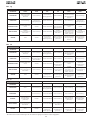
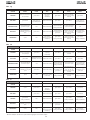
Tab. 1/b
Tab. 1/a
Tab. 1/c
LOGIC “A” PULSES
AUTOMATED SYSTEM
STATUS
OPEN A CLOSE STOP FSW LOOP 1 LOOP 2
CLOSED
opens and closes after
pause time
no effect
no effect
(opening disabled) no effect
opens and at end
of opening closes if
released
no effect
OPENING no effect
reverses
immediately at
closing
stops operation no effect no effect no effect
OPEN IN PAUSE recharges pause time closes stops operation
recharges pause
time
(closing disabled)
recharges pause time
recharges pause
time
(closing disabled)
CLOSING
reverses immediately
at opening
no effect stops operation
reverses
immediately at
opening
reverses immediately
at opening and closes
at end of opening if
released
reverses
immediately at
opening
STOPPED closes closes
no effect
(opening and
closing disabled)
no effect
(closing disabled)
opens and at end
of opening closes if
released
no effect
(closing disabled)
LOGIC “A1” PULSES
AUTOMATED SYSTEM
STATUS
OPEN A CLOSE STOP FSW LOOP 1 LOOP 2
CLOSED
opens and closes after
pause time
no effect
no effect
(opening disabled)
no effect
opens and at end
of opening closes if
released
no effect
OPENING no effect
reverses
immediately at
closing
stops operation
closes immediately
at end of opening
no effect
closes immediately
at end of opening
OPEN IN PAUSE recharges pause time closes stops operation closes recharges pause time closes
CLOSING
reverses immediately
at opening
no effect stops operation
reverses
immediately at
opening
reverses immediately
at opening and closes
at end of opening if
released
reverses
immediately at
opening
STOPPED closes closes
no effect
(opening and clo-
sing disabled)
no effect
(closing disabled)
opens and at end
of opening closes if
released
no effect
(closing disabled)
LOGIC “E” PULSES
AUTOMATED SYSTEM
STATUS
OPEN A CLOSE STOP FSW LOOP 1 LOOP 2
CLOSED opens no effect
no effect
(opening disabled)
no effect
opens and at end
of opening closes if
released
no effect
OPENING stops operation
reverses
immediately at
closing
stops operation no effect no effect no effect
OPEN closes closes
no effect
(closing disabled)
no effect
(closing disabled)
no effect
no effect
(closing disabled)
CLOSING
reverses immediately
at opening
no effect stops operation
reverses
immediately at
opening
reverses immediately
at opening and closes
at end of opening if
released
reverses
immediately at
opening
STOPPED closes closes
no effect
(opening and clo-
sing disabled)
no effect
(closing disabled)
opens and at end
of opening closes if
released
no effect
(closing disabled)
In brackets: effects on the other inputs when pulse active
La page est en cours de chargement...
La page est en cours de chargement...
La page est en cours de chargement...
La page est en cours de chargement...
La page est en cours de chargement...
La page est en cours de chargement...
La page est en cours de chargement...
La page est en cours de chargement...
La page est en cours de chargement...
La page est en cours de chargement...
La page est en cours de chargement...
La page est en cours de chargement...
La page est en cours de chargement...
La page est en cours de chargement...
La page est en cours de chargement...
La page est en cours de chargement...
La page est en cours de chargement...
La page est en cours de chargement...
La page est en cours de chargement...
La page est en cours de chargement...
La page est en cours de chargement...
La page est en cours de chargement...
La page est en cours de chargement...
La page est en cours de chargement...
La page est en cours de chargement...
La page est en cours de chargement...
La page est en cours de chargement...
La page est en cours de chargement...
La page est en cours de chargement...
La page est en cours de chargement...
La page est en cours de chargement...
La page est en cours de chargement...
La page est en cours de chargement...
La page est en cours de chargement...
La page est en cours de chargement...
La page est en cours de chargement...
La page est en cours de chargement...
La page est en cours de chargement...
La page est en cours de chargement...
La page est en cours de chargement...
La page est en cours de chargement...
La page est en cours de chargement...
La page est en cours de chargement...
La page est en cours de chargement...
-
 1
1
-
 2
2
-
 3
3
-
 4
4
-
 5
5
-
 6
6
-
 7
7
-
 8
8
-
 9
9
-
 10
10
-
 11
11
-
 12
12
-
 13
13
-
 14
14
-
 15
15
-
 16
16
-
 17
17
-
 18
18
-
 19
19
-
 20
20
-
 21
21
-
 22
22
-
 23
23
-
 24
24
-
 25
25
-
 26
26
-
 27
27
-
 28
28
-
 29
29
-
 30
30
-
 31
31
-
 32
32
-
 33
33
-
 34
34
-
 35
35
-
 36
36
-
 37
37
-
 38
38
-
 39
39
-
 40
40
-
 41
41
-
 42
42
-
 43
43
-
 44
44
-
 45
45
-
 46
46
-
 47
47
-
 48
48
-
 49
49
-
 50
50
-
 51
51
-
 52
52
-
 53
53
-
 54
54
-
 55
55
-
 56
56
-
 57
57
-
 58
58
-
 59
59
-
 60
60
-
 61
61
-
 62
62
-
 63
63
-
 64
64


dans d''autres langues
- italiano: Genius 624 Istruzioni per l'uso
- español: Genius 624 Instrucciones de operación
- Deutsch: Genius 624 Bedienungsanleitung
- Nederlands: Genius 624 Handleiding
Documents connexes
-
Genius LYNX 08 Mode d'emploi
-
Genius LINX07 Mode d'emploi
-
-
-
-
Genius SPRINT382 383 Mode d'emploi
-
Genius JA466 Le manuel du propriétaire
-
-