Simplicity 040330GE-0 Guide d'installation
- Catégorie
- Groupes électrogènes
- Taper
- Guide d'installation
Ce manuel convient également à

Installation and
Start-Up Manual
GE Home Generator Systems
15,000 and 20,000 Watt
Home Generator System

2
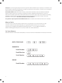
DATE OF PURCHASE
GENERATOR
Model Number
Model Number
Model Revision
Serial Number
ENGINE
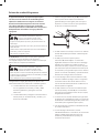
Thank you for purchasing this quality-built GE home generator. We’re pleased that you’ve placed your confidence in the
GE brand. When operated and maintained according to the instructions in the operator’s manual, your home generator
will provide many years of dependable service.
This manual contains safety information to make you aware of the hazards and risks associated with residential
generator systems and how to avoid them. This generator system is designed and intended only for use as an
optional home standby system that provides an alternate source of electric power and to serve loads such as heating,
refrigeration systems, and communication systems that, when stopped during any power outage, could cause
discomfort or inconvenience. Save these instructions for future reference.
This generator requires professional installation before use. The installer should follow the instructions completely.
Where to Find Us
You never have to look far to find support and service for your generator. For quick service when you need
it most fill out the information below and keep your original receipt with this manual. You may contact
Customer Service at 888 575-8226 between 8:00 AM and 5:00 PM CT., or click on SERVICE & SUPPORT at
www.homestandbygeneratorsystems.com, which provides a list of authorized dealers.
For Future Reference
Please fill out the information below and keep with your receipt to assist in unit identification for future purchase issues.

3
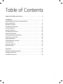
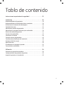
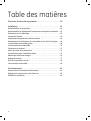
Table of Contents
Important Safety Instructions ...............................4
Installation ................................................7
Installing Dealer/Contractor Responsibilities............................7
Delivery Inspection ...................................................8
Generator Location ...................................................8
The Gaseous Fuel System ............................................12
Fuel Consumption ...................................................14
System Connectors ..................................................15
Grounding the Generator.............................................16
System Control Panel ................................................18
Final Installation Considerations ......................................19
Initial Start-up (No Load) .............................................20
Engine Adjustment ..................................................21
Test Shutdown(s) Procedure ..........................................22
Fuel Conversion .....................................................24
Schematic Diagram..................................................25
Wiring Diagram .....................................................26
Operation.................................................27
Automatic Operation Sequence .......................................27
Setting Exercise Timer ...............................................27
Installation Inspection ...............................................28

4
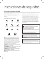
Safety Rules
SAVE THESE INSTRUCTIONS - This manual contains
important instructions that should be followed during
installation and maintenance of the generator and batteries.
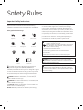
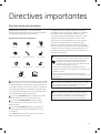
Safety Symbols and Meanings
The safety alert symbol indicates a potential personal
injury hazard. A signal word (DANGER, WARNING, or
CAUTION) is used with the alert symbol to designate a degree
or level of hazard seriousness. A safety symbol may be used
to represent the type of hazard. The signal word NOTICE is
used to address practices not related to personal injury.
DANGER indicates a hazard which, if not avoided, will
result in death or serious injury.
WARNING indicates a hazard which, if not avoided, could
result in death or serious injury.
CAUTION indicates a hazard which, if not avoided, could
result in minor or moderate injury.
NOTICE addresses practices not related to personal injury.
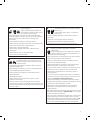
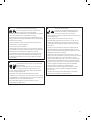
Important Safety Instructions
Explosion
Fire
Electrical Shock
Rotating Parts
Hot Surface
Toxic Fumes
Chemical BurnExplosive PressureAuto Start
Lift Hazard
Read Manual
The manufacturer cannot possibly anticipate every possible
circumstance that might involve a hazard. The warnings
in this manual, and the tags and decals affixed to the unit
are, therefore, not all-inclusive. If you use a procedure, work
method or operating technique that the manufacturer does
not specifically recommend, you must satisfy yourself that it
is safe for you and others. You must also make sure that the
procedure, work method or operating technique that you
choose does not render the generator system unsafe.
WARNING Running engine gives off carbon monoxide, an
odorless, colorless, poison gas.
Breathing carbon monoxide could result in death, serious
injury, headache, fatigue, dizziness, vomiting, confusion,
seizures, nausea or fainting.
Operate this product ONLY outdoors.•
Install a battery operated carbon monoxide alarm near •
the bedrooms.
Keep exhaust gas from entering a confined area through •
windows, doors, ventilation intakes, or other openings.
WARNING The engine exhaust from this product contains
chemicals known to the State of California to cause cancer, birth
defects, or other reproductive harm.
WARNING Certain components in this product and related
accessories contain chemicals known to the State of California
to cause cancer, birth defects, or other reproductive harm. Wash
hands after handling.

5
WARNING Storage batteries give off explosive hydrogen gas
during recharging.
Slightest spark will ignite hydrogen and
cause explosion, resulting in death, serious
injury and/or property damage.
Battery electrolyte fluid contains acid and is extremely caustic.
Contact with battery contents could cause severe chemical burns.
A battery presents a risk of electrical shock and high short
circuit current.
DO NOT dispose of battery in a fire. Recycle battery.•
DO NOT allow any open flame, spark, heat, or lit cigarette during •
and for several minutes after charging a battery.
DO NOT open or mutilate the battery.•
Wear protective goggles, rubber apron, rubber boots and •
rubber gloves.
Remove watches, rings, or other metal objects.•
Use tools having insulated handles.•
WARNING Generator produces hazardous voltage.
Failure to properly ground generator could result
in electrocution.
Failure to isolate generator from utility power could result
in death or serious injury to electric utility workers due to
backfeed of electrical energy.
When using generator for backup power, notify utility company.•
DO NOT touch bare wires or bare receptacles.•
DO NOT use generator with electrical cords which are worn, •
frayed, bare or otherwise damaged.
DO NOT handle generator or electrical cords while standing in •
water, while barefoot, or while hands or feet are wet.
If you must work around a unit while it is operating, stand on an •
insulated dry surface to reduce the risk of a shock hazard.
DO NOT allow unqualified persons or children to operate or •
service generator.
In case of an accident caused by electrical shock, immediately •
shut down the source of electrical power and contact the local
authorities. Avoid direct contact with the victim.
Despite the safe design of the residential generator, operating •
this equipment imprudently, neglecting its maintenance or being
careless could cause possible injury or death.
Remain alert at all times while working on this equipment. •
Never work on the equipment when you are physically or
mentally fatigued.
Before performing any maintenance on the generator, disconnect •
the battery cable indicated by a NEGATIVE, NEG or (-) first. When
finished, reconnect that cable last.
After your system is installed, the generator may crank and start •
without warning any time there is a power failure. To prevent
possible injury, always set the generator’s system switch to OFF,
remove the service disconnect from the disconnect box AND
remove the 15 Amp fuse BEFORE working on the equipment.
WARNING Propane and Natural Gas are extremely flammable
and explosive, which could cause burns, fire or
explosion resulting in death, serious injury and/or
property damage.
Install the fuel supply system according to NFPA 37 and other •
applicable fuel-gas codes.
Before placing the generator into service, the fuel system lines •
must be properly purged and leak tested.
After the generator is installed, you should inspect the fuel •
system periodically.
NO leakage is permitted.•
DO NOT operate engine if smell of fuel is present or other •
explosive conditions exist.
DO NOT smoke around the generator. Wipe up any oil spills •
immediately. Ensure that no combustible materials are left in the
generator compartment. Keep the area near the generator clean
and free of debris.
WARNING Hazardous Voltage - Contact with power lines could
cause electric shock or burn, resulting in death or
serious injury.
Lifting Hazard / Heavy Object - Could result in
serious injury.
If lifting or hoisting equipment is used, DO NOT contact any •
power lines.
DO NOT lift or move generator without assistance.•
Use lifting pipes as described in • Lifting the Generator.
DO NOT lift unit by roof as damage to generator will occur.•

6
WARNING Exhaust heat/gases could ignite combustibles or
structures resulting in death, serious injury and/or
property damage.
Contact with muffler area could cause burns
resulting in serious injury.
DO NOT touch hot parts and AVOID hot exhaust gases.•
Allow equipment to cool before touching.•
DO NOT install the generator closer than 5 feet (1.5m) from any •
combustibles or structures with combustible walls having a fire
resistance rating of less than 1 hour.
Keep at least minimum distances shown in • General Location
Guidelines to insure for proper generator cooling and
maintenance clearances.
It is a violation of California Public Resource Code, Section 4442, •
to use or operate the engine on any forest-covered, brush-
covered, or grass-covered land unless the exhaust system is
equipped with a spark arrester, as defined in Section 4442,
maintained in effective working order. Other states or federal
jurisdictions may have similar laws.
Contact the original equipment manufacturer, retailer, or dealer to
obtain a spark arrester designed for the exhaust system installed
on this engine.
Replacement parts must be the same and installed in the same •
position as the original parts.
WARNING Starter and other rotating parts could entangle
hands, hair, clothing, or accessories resulting in
serious injury.
NEVER operate generator without protective housings, covers, or •
guards in place.
DO NOT wear loose clothing, jewelry or anything that could be •
caught in the starter or other rotating parts.
Tie up long hair and remove jewelry.•
Before servicing, remove 15 Amp fuse from control panel and •
disconnect Negative (NEG or -) battery cable.
CAUTION Installing the 15A fuse could cause the engine
to start at any time without warning resulting in minor or
moderate injury.
Observe that the 15 Amp fuse has been removed from the control •
panel for shipping.
DO NOT install this fuse until all plumbing and wiring has been •
completed and inspected.
CAUTION Excessively high operating speeds could result in
minor injury and/or equipment damage.
Excessively low speeds impose a heavy load on generator.
DO NOT tamper with governed speed. Generator supplies correct •
rated frequency and voltage when running at governed speed.
DO NOT modify generator in any way.•
NOTICE Improper treatment of generator could damage it and
shorten its life.
Use generator only for intended uses.•
If you have questions about intended use, contact your •
authorized dealer.
Operate generator only on level surfaces.•
Adequate, unobstructed flow of cooling and ventilating air is •
critical to correct generator operation.
The access panels/door must be installed whenever the unit •
is running.
DO NOT expose generator to excessive moisture, dust, dirt, or •
corrosive vapors.
Remain alert at all times while working on this equipment. •
Never work on the equipment when you are physically or
mentally fatigued.
DO NOT start engine with air cleaner or air cleaner cover removed.•
DO NOT insert any objects through cooling slots.•
DO NOT use the generator or any of its parts as a step. Stepping •
on the unit could cause stress and break parts. This may result in
dangerous operating conditions from leaking exhaust gases, fuel
leakage, oil leakage, etc.
If connected devices overheat, turn them off and disconnect them •
from generator.
Shut off generator if: •
-electrical output is lost;
-equipment sparks, smokes, or emits flames;
-unit vibrates excessively.
NOTICE Exceeding generators wattage/amperage capacity could
damage generator and/or electrical devices connected to it.
Start generator and let engine stabilize before connecting •
electrical loads.

7
If operating the generator below 40°F (5°C), it is HIGHLY
RECOMMENDED that a Model 6030 Cold Weather Kit
(includes oil warmer and battery warmer) and a Model 6174
Cold Weather Breather Kit (includes engine duct) be installed.
These items are available at your local servicing dealer.
If you need more information on this matter, please call
(888) 575-8226, between 8:00 AM and 5:00 PM CT.
• Readandobservethesafetyrules.
• InstallonlyanULapprovedtransferswitchthatis
compatible with the generator.
• Readandfollowtheinstructionsgiveninthis
installation and start-up manual.
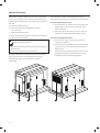
Installing Dealer/Contractor Responsibilities
The unit is shipped bolted to its mounting pad, ready for
installation. Avoid damage from dropping, bumping, collision,
etc. Store and unpack carton with the proper side up, as
noted on the shipping carton.
Unpacking Precautions
Installation
This product is intended for use as an optional home
generator system which provides an alternate source
of electric power and to serve loads such as heating,
refrigeration systems, and communication systems that,
when stopped during any power outage, could cause
discomfort or inconvenience. This product does not qualify
for emergency standby as defined by NFPA 70 (NEC).
Every effort has been made to ensure that information in this
manual is accurate and current. However, we reserve the
right to change, alter, or otherwise improve the product and
this document at any time without prior notice.
Only current licensed electrical and plumbing
professionals should attempt home generator system
installations. Installations must strictly comply with all
applicable codes, industry standards and regulations.
• Readandfollowtheinstructionsgiveninthe
operator’s manual.
• Followaregularscheduleinmaintaining,caringfor
and using your home generator, as specified in the
operator’s manual.
Home Owner Responsibilities

8
After removing the carton, carefully inspect the generator for
any damage that may have occurred during shipment.
If loss or damage is noted at time of delivery, have the
person(s) making delivery note all damage on the freight bill
and affix his signature under the consignor’s memo of loss or
damage. If loss or damage is noted after delivery, separate
the damaged materials and contact the carrier for claim
procedures. Missing or damaged parts are not warranted.
Delivery Inspection
The home generator system is supplied with:
• Pre-attachedmountingpad
• Fully-servicedoil/lubricatingsystem
• Flexiblefuelhook-uphose
• Installationandstart-upmanual
• Operator’smanual
• Engineoperator’smanual
• Installationchecklist
• Alternatorcover
• Spareaccessdoorkeys
• Spare15AmpATO-typefuse
• Two-pincontrolpanelconnector
• Ten-pincontrolpanelconnector
• Touchuppaint
Not supplied:
• Startingbattery(seepage19)
• Connectingwireandconduit
• Fuelsupplyvalves/plumbing
• Crane,liftingstraps,chainsorcables
• Two48”lengthsof1”pipe(NOTconduit)
• Holepunchesfor16gasteel
• Torquescrewdriver,5to50inch-poundrange
• Voltage/frequencymeter
• Variousspecialtoolsandequipment
Shipment Contents
Before installing the generator, consult with the homeowner
and convey the following guidelines, which may affect the
desired installation location.
Generator Location
WARNING Exhaust heat/gases could ignite combustibles
or structures resulting in death, serious injury and/or
property damage.
DO NOT install the generator closer than 5 feet (1.5m) from any •
combustibles or structures with combustible walls having a fire
resistance rating of less than 1 hour.
WARNING Running engine gives off carbon monoxide, an
odorless, colorless, poison gas.
Breathing carbon monoxide could result in death, serious
injury, headache, fatigue, dizziness, vomiting, confusion,
seizures, nausea or fainting.
Operate this product ONLY outdoors.•
Install a battery operated carbon monoxide alarm near •
the bedrooms.
Keep exhaust gas from entering a confined area through •
windows, doors, ventilation intakes, or other openings.

9
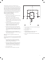
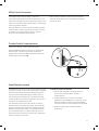
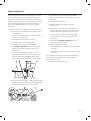
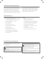
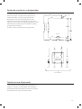
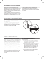
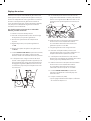
A Non-Combustible material with Fire Resistant Rating of
1 hour or greater
B Home Standby Generator
C Engine Exhaust
D Combustible Material or Structure with a Fire
Resistance Rating of less than 1 hour.
E Any structure or material. DO NOT connect (A) and/or
(D) to (E).
Install generator outdoors in an area which will not
accumulate deadly exhaust gas. DO NOT install generator
where exhaust gas could accumulate and enter inside or be
drawn into a potentially occupied building. Ensure exhaust
gas is kept away from windows, doors, ventilation intakes
or other openings that can allow exhaust gas to collect in a
confined area. Prevailing winds and air currents should be
taken into consideration when positioning generator.
General Location Guidelines
• InstalltheunitoutdoorsONLY.
• Placetheunitinapreparedlocationthatisflatand
has provisions for water drainage.
• Installtheunitinalocationwheresumppump
discharge, rain gutter down spouts, roof run-off,
landscape irrigation, or water sprinklers will not flood
the unit or spray the enclosure and enter any air inlet
or outlet openings.
• Installtheunitwhereitwillnotaffectorobstruct
any services (including covered, concealed and
underground), such as telephone, electric, fuel,
irrigation, air conditioning, and so forth.
• Installtheunitwhereairinletandoutletopenings
will not become obstructed by leaves, grass, snow,
etc. If prevailing winds will cause blowing or drifting,
you may need to construct a windbreak to protect
the unit.
• Installthegeneratorascloseaspossibletothe
transfer switch and fuel supply to reduce the length of
wiring, conduit, and piping.
Laws or local codes may regulate the distance to the
fuel supply.
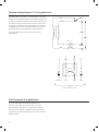
The minimum clearances from aerial view of generator (B) to
combustible (D), and non-combustible (A) materials is shown
at right:
• Thesedistancesareprovidedtogivegenerator
location guidance relative ONLY to combustibles,
generator cooling, and maintenance.
• Theminimumdistancesinthefigureareasshown.
All four sides of the generator cannot be enclosed
or restricted, even if the minimum distances are
maintained. DO NOT connect (A) and/or (D) to (E)
• Aroofcannotbeused.
• Exhaust(C) must not be allowed to accumulate.
C
D A
B
E
E
5’ (1.5 m)
3’ (1 m)
2’ (.62 m)
5’ (1.5 m)
5’ (1.5 m)
5’ (1.5 m)

10
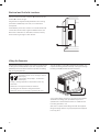
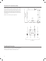
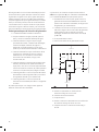
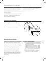
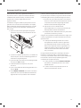
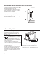
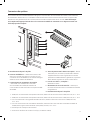
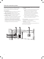
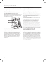
Electrical and Fuel Inlet Locations
The 3/4 inch N.P.T. fuel inlet connector (A) and electrical inlet
location (B) is shown at right.
The generator is shipped already attached to its mounting
pad. Unless mandated by local code, a concrete slab is
not required.
If mandated by local code, construct a concrete slab at least
3 inches thick and 6 inches longer and wider than the unit.
Attachunittoslabwith1/4”diameter(minimum)masonry
anchor bolts long enough to retain the unit.
A
B
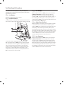
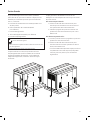
The generator weighs more than 240 kg (530 pounds) (15 kW)
or 260 kg (575 pounds) (20kW). Proper tools, equipment and
qualified personnel should be used in all phases of handling
and moving the generator.
Lifting the Generator
Two48”lengthsof1”pipe(C), supplied by the installer, are
required to lift the generator manually. Insert pipes through
the lifting holes (D) located near the unit’s base.
Youmayalsolifttheunitusinga“hookandhoist”method
attached to the lifting pipes, provided that you use a
spreader bar to ensure that the chains or cables DO NOT
touch the generator’s roof.
After unit is in place, fill the lifting holes with the supplied
lifting hole plugs. Retouch any chipped paint with supplied
touch-up paint.
C
D
WARNING Hazardous Voltage - Contact with power lines could
cause electric shock or burn, resulting in death or
serious injury.
Lifting Hazard / Heavy Object - Could result in
serious injury.
If lifting or hoisting equipment is used, DO NOT contact any •
power lines.
DO NOT lift or move generator without assistance.•
Use lifting pipes as described in • Lifting the Generator.
DO NOT lift unit by roof as damage to generator will occur.•

11
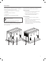
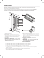
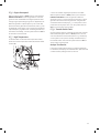
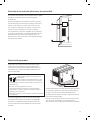
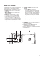
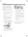
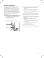
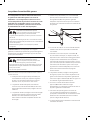
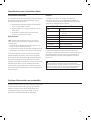
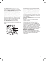
The home generator is equipped with an enclosure that has
several access doors. The doors are named for a significant
component located behind them, as follows:
A Control Panel door (shipped loose - to be attached
by installer)
B Fuel Inlet Port (shown for reference)
C Oil Drain door
D Exhaust Port (cover to be attached by installer)
E Oil Fill door
The oil and control panel doors must be installed whenever
the unit is running to assure proper cooling, reduce noise,
and for added safety.
Access Ports
Each home generator is supplied with a set of identical keys.
These keys fit the locks that secure the access doors.
To open access door:
1. Insert key into lock of access door handle and turn
key one quarter turn counterclockwise.
2. Grasp door’s handle and turn one quarter turn
counterclockwise to open. Remove key.
To close access door:
1. Close door and turn door’s handle one quarter
turn clockwise.
2. Insert key into lock of door handle and turn key one
quarter turn clockwise. Remove key.
Additional force may be required to fully close and
lock the doors because they create a pressurized seal
for the generator enclosure.
A DB EC
WARNING Contact with muffler area could cause burns
resulting in serious injury.
DO NOT touch hot parts and AVOID hot exhaust gases.•
Allow equipment to cool before touching.•

12
The information below is provided to assist gaseous fuel
system technicians in planning installations. In no way
should this information be interpreted to conflict with
applicable fuel gas codes. Consult with your local fuel
supplier or Fire Marshall if questions or problems arise.
TO THE INSTALLER: Consult with the generator owner(s) and
convey any technical considerations that might affect their
installation plans before applying these general guidelines.
The following general rules apply to gaseous fuel
system piping:
WARNING Propane and Natural Gas are extremely flammable
and explosive, which could cause burns, fire or
explosion resulting in death, serious injury and/or
property damage.
Before placing the generator into service, the fuel system lines •
must be properly purged and leak tested.
No leakage is permitted.•
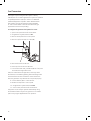
NOTICE The supplied flexible gaseous pipe is not to be installed
underground or in contact with the ground.
• The entire flexible gaseous pipe must be visible for
periodic inspection and must not be concealed
within nor contact nor run through any wall, floor, or
partition.
• Thepipingshouldbeofamaterialthatconforms
to federal and local codes, rigidly mounted and
protected against vibration.
• Pipingshouldbeprotectedfromphysicaldamage
where it passes through flower beds, shrub beds, and
other cultivated areas where damage could occur.
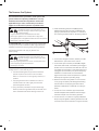
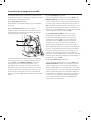
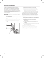
The Gaseous Fuel System
• Installtheflexible,gaseoushose(B) (supplied)
between the generator fuel inlet port (A) and rigid
piping to prevent thermal expansion or contraction
from causing excessive stress on the piping material.
A
B
C
E
D
F
• Aunion(C) or flanged connection shall be provided
downstream to permit removal of controls.
• Amanometerportshouldbeprovided(D). A digital
manometer,P/N19495,isavailableatyourBriggs&
Stratton service center. When the initial test runs are
completed, the manometer is removed and the port
is plugged. The manometer port permits temporary
installation of a manometer to ensure that the
engine receives the correct fuel pressure to operate
efficiently throughout its operating range.
• Wheretheformationofhydratesoriceisknownto
occur, piping should be protected against freezing.
The termination of hard piping should include a
sediment trap (F) where condensate is not likely to
freeze.
• Aminimumofoneaccessible,approvedmanual
shutoff valve (E) shall be installed in the fuel supply
line within 6 ft (180 cm) of the home generator.
• Aminimum10ft.(3m)sectionofgaspipebetween
the primary fuel regulator and the generator fuel inlet
connection (acts as accumulator for high block loads).
WARNING Propane and Natural Gas are extremely flammable
and explosive, which could cause burns, fire or
explosion resulting in death, serious injury and/or
property damage.
LP gas is heavier than air and will settle in low areas.•
Natural gas is lighter than air and will collect in high areas.•
The slightest spark could ignite these fuels and cause an explosion.•
DO NOT light a cigarette or smoke.•

13
Fuel Pipe Sizing
There are numerous on-line or otherwise-published
references for fuel pipe sizing. For example, NFPA 54 -
National Fuel Gas Code, 2006 (Item #: 320-6031-06) is a
common resource.
The installer should consider the specific gravity of gas
and compensate for a nominal amount of restriction from
bends, fittings, etc. If an unusual number of fittings, bends, or
other restrictions are used, refer to federal and local codes
for guidance.
• Amanualfuelshut-offvalvelocatedintheinteriorof
the building.
• Wherelocalconditionsincludeearthquake,
tornado, unstable ground, or flood hazards, special
consideration shall be given to increase strength and
flexibility of piping supports and connections.
• Pipingmustbeofthecorrectsizetomaintainthe
required supply pressures and volume flow under
varying generator load conditions with all gas
appliances connected to the fuel system turned on
and operating.
• Useapipesealantorjointcompoundapprovedfor
use with NG/LPG on all threaded fittings to reduce the
possibility of leakage.
• Installedpipingmustbeproperlypurgedand
leak tested, in accordance with applicable codes
and standards.
Fuel Pressure
Both LP vapor and natural gas fuel supply pressure at the
generator’s fuel inlet port should be between the following
levels at full load with all gas appliances turned on and
operating.
• NGis5-7”W.C.
• LPis11-14”W.C.
Maximum pressure with engine OFF at No Load is 13.85 psi.
Power Loss
Air density is less at high altitudes, resulting in less available
engine power. Specifically, engine power will decrease 3.5%
for each 1,000 feet (300 m) above sea level and 1% for each
10° F (5.6°C) above 77°F (25°C). Generators located in these
conditions must have their transfer switch programmed
appropriately for this power decrease.

14
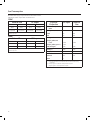
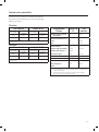
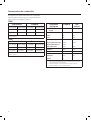
Fuel Consumption
Estimated fuel supply requirements at half and full load for
natural gas and LP vapor fuels are shown here.
15kW
Natural Gas LP Vapor
1/2 Load Full Load 1/2 Load Full Load
126 C 242 C 56 C 108 C
126,000 B 242,000 B 140,000 B 270,000 B
C = Cubic feet per hour
B = BTU’s per hour
20kW
Natural Gas LP Vapor
1/2 Load Full Load 1/2 Load Full Load
160 C 293C 70.4 C 141.5 C
160,000 B 293,000B 176,725 B 353,650 B
C = Cubic feet per hour
B = BTU’s per hour
Physical
Properties
LP Vapor Natural
Gas
Normal Atmospheric
State
Gas Gas
Boiling Point (in °F):
Initial
End
-44
-44
-259
-259
Heating Value:
BTU per gallon (Net
LHV*)
BTU per gallon (gross**)
Cubic feet (gas)
83,340
91,547
2,500
63,310
1,000
Density*** 36.39 57.75
Weight† 4.24 2.65
Octane Number:
Research
Motor
110+
97
110+
* LHV (Low Heat Value) is the more realistic rating.
** Gross heat value does not consider heat lost in the form of water during
combustion.
*** Densityisgivenin“CubicFeetofGasperGallonofLiquid”.
† Weightisgivenin“PoundsperGallonofLiquid”.

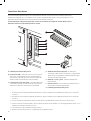
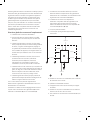
15
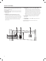
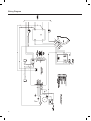
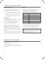
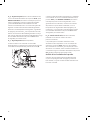
Low Voltage connections to signal fault contacts, transfer switch communication, remote LED and auxiliary 12VDC
power are made via a removable ten-pin connector plug.
Compare this illustration with your generator to familiarize yourself with the location of these connections: Count down
to the proper pin location on the control board because visual alignment with the decal can be misleading.
System Connectors
A – Ten-pin Connector Plug
B - Fault Contacts—UseNO,COMandNCtohookupa
siren, light, etc. to alert you in case of a fault. Contacts
reverse state (NO goes to NC and vice versa) upon a
fault condition.
C - Transfer Switch Communication—Connecttotransfer
switch control board for communication interface using
18AWG copper twisted pair wire.
D - Remote LED Output (Optional)—Usethistohookupthe
remote LED supplied with the generator. The remote LED
will turn on and off in a series of blinks if certain faults are
detected in the generator.
E - +12 Volt DC, .5 Amp Output—Internalauxiliary
power supply.
F - 240 Volt Utility—Usetohookupthe240Vutilityleads
from the transfer switch to the generator.
G – Two-pin Connector Plug
• For15kWpoweroutputconnection,use#6AWGminimum300volt75°C-90°Ccopperwire
• For20kWpoweroutputconnection,use#4AWGminimum300volt75°C-90°Ccopperwire
• ForUtilityCircuitconnectionuse#14AWGminimum300volt75°C-90°Ccopperwire
• Fortransferswitchcommunicationuse#18AWGtwistedpairconductors,nogreaterthan200ftinlength,300volt
75°C-90°Ccopperwire
• Whenconnectingtotheconnectorplugs,fastenonlyonewiretoeachconnectorscrew.
• Torqueconnectorplugscrewsto7in-lb(7.9Newtonmeter).
C
E
D
A
B
F
G

16
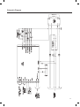
Generator AC Connection System
A single-phase, three-wire AC connection system is used in
the home generator. The stator assembly consists of a pair
of stationary windings with two leads brought out of each
winding. The junction of leads 22 and 33 forms the neutral
lead, as shown schematically and as a wiring diagram. A
complete schematic and wiring diagram can be found later
in this manual.
Neutral is not bonded to ground at generator.
33
240V
11
22
44
11
22
44
120V
120V
0
Ground
Power Winding
Circuit
Breaker
Line 1
Neutral
To Transfer Switch
Line 2 Neutral
Circuit
Breaker
Ground the generator per applicable codes, standards, and
regulations. The generator GND lug is located inside the
control panel door under the circuit breaker cover.
Grounding the Generator

17
Fault Detection System
The generator may have to run for long periods of time with
no operator present. For that reason, the system is equipped
with sensors that automatically shut down the generator
in the event of potentially damaging conditions, such as
low oil pressure, high temperature, over speed, and other
conditions. Refer to Fault Detection System in the operator’s
manual for more detailed information.
The owner will use the remote LED indicator to observe
the status of the home generator system. The remote LED
will turn on and off in a series of blinks if certain faults are
detected in the generator system. Consult with the owner
for a convenient location. Locate the electrical box in an
area visible by the home owner such as near a garage door
opener or security control panel.
To install the remote LED indicator:
1. Push the LED through the mounting plate from
the front until it snaps in place. The LED is
polarity sensitive.
2. Using provided 10 pin connector and installer-
supplied minimum 18AWG wire, connect the remote
LED to the generator control board +LED and GND
connection. Use wire nuts to attach wire to LED leads.
3. Attach mounting plate to installer-supplied
electrical box.
Utility Circuit Connection
“240VUtility”leadsmustberoutedinconduit.The
“240VUtility”leadsdeliverpowertothegenerator’scircuit
board, optional battery warmer and optional oil warmer. This
power also charges the battery. When power on these leads
is lost, the generator will start.
Using provided 2 pin connector plug and installer-supplied
minimum 300V, 14 AWG copper wire, connect each control
circuit terminal in the generator to the two-amp fuse
terminals in the automatic transfer switch.
When making connections, obey wire type and torque
specifications printed on the circuit breaker and neutral/
ground connector.
A
B
Transfer Switch Communication
(Units with an ACCM II or later control board only)
Using #18 AWG twisted pair conductors, no greater than
200 ft in length, connect Tx Rx and Tx Rx Ground from
the generator control panel (A) to the GND and T/R on the
transfer switch control board (B).

18
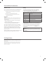
System Control Panel
The home generator control panel, located inside the control
panel door, is shown below. Brief descriptions of the controls
used during installation are:
A - SET EXERCISE —Usedtosettheexercisecyclestarttime.
B – MANUAL OVER-RIDE—Usedtomanuallystartandstop
the generator.
C - 15 Amp Fuse—ProtectsthegeneratorDCcontrol
circuits. If the fuse has ‘blown’ (melted open) or was
removed, the engine cannot crank or start. Replace the
fuse using only an identical ATO 15A fuse. One spare fuse
is supplied with the unit. If fuse was blown or removed,
you will need to reset the exercise timer (see Setting
Exercise Timer).
D - System Switch—SwitchesmodestoOFF or AUTO.
• “AUTO”positionisthenormaloperatingposition.Ifa
utility power outage is sensed, the system will start
the generator. When utility power is restored, lets the
engine stabilize internal temperatures, shuts off the
generator, and waits for the next utility power outage.
• “OFF”positionturnsoffrunninggenerator,prevents
unit from starting and resets any detected faults.
E - Digital Display—Displaysrunningtimeinhoursor
fault codes.
F - Circuit Breaker —MustbeON to supply power to the
transfer switch.
More information may be found in Controls in the
operator’s manual.
A
D
B
E
C
F

19
Fuel Supply System
Ensure that all fuel pipe connections are tight, secure and
without leaks.
Ensure that all gas line shutoff valves are OPEN and that
adequate fuel pressure is available whenever automatic
operation is desired.
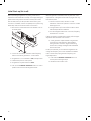
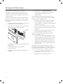
Alternator Cover
The unit’s alternator-end enclosure cover is shipped loose in
the carton. Attach the cover to the enclosure as follows:
1. Position cover’s two locating pins over matching
enclosure holes.
2. Press in on cover until it snaps in place.
3. Using supplied self-drill screws, fasten cover to
enclosure at six places.
Engine Oil
This engine is shipped from the factory pre-run and filled
with synthetic oil (API SJ/CF 5W-30). This allows for system
operation in a wide range of temperature and climate
conditions. Before starting the engine, check oil level and
ensure that engine is serviced as described in the engine
operator’s manual.
The use of synthetic oil does not alter the required oil change
intervals described in the engine operator’s manual.
Final Installation Considerations
Battery
The installer must supply and install a valve-regulated
rechargeable starting battery. The starting battery MUST
conform to the specifications shown in this chart.
Battery Specifications
Volts 12 Volt DC
Amps (MIN) 600 CCA (cold cranking amps)
Type AGM (absorbent glass mat)
Terminal Hardware M6
Dimensions (MAX):
Width 5.5 inches (140mm)
Length 9.0inches(230mm)
Height 8.25 inches (210mm)
Install the battery as described in Servicing the Battery in
the Maintenance section of the operator’s manual. Installer
must connect battery charge wire (wire #13) to positive
battery terminal! Always make sure the NEGATIVE cable is
connected last.
NOTICE Any attempt to crank or start the engine before it has
been properly serviced with the recommended oil will result in
equipment failure.
Refer to • Maintenance in the operator’s manual and engine
manual for oil fill information.
Damage to equipment resulting from failure to follow this •
instruction will void engine and generator warranty.
WARNING Battery posts, terminals and related accessories
contain lead and lead compounds, chemicals known to the State
of California to cause cancer and reproductive harm. Wash hands
after handling.

20
Initial Start-up (No Load)
Before operating the generator or placing it into service,
inspect the entire installation carefully. Then begin testing the
system without any electrical loads connected, as follows:
Unit has been set-up for NG operation at the factory. Fuel
conversion, if needed, must be completed prior to performing
these steps. See Fuel Conversion later in this section.
1. Remove four screws that hold circuit breaker cover to
air intake guard.
2. Connect an accurate AC voltmeter and a frequency
meter to line side of generator’s circuit breaker.
3. Set generator’s circuit breaker to ON (closed) position.
4. Install 15 Amp fuse in control panel.
5. Set generator’s system switch to AUTO.
6. Push and hold MANUAL OVER-RIDE button on control
panel for about six seconds. Engine will start.
When the generator is started for the very first time, it will
require that air in the gaseous fuel lines be purged. This may
take a few minutes.
7. Listen for unusual noises, vibration or other
indications of abnormal operation. Check for oil leaks
while engine runs.
8. Let engine warm up for about five minutes to allow
internal temperatures to stabilize.
9. No-loadvoltageshouldbe239-262Volts,frequency
should be 62.0 - 62.5 Hz.
If either parameter is outside these ranges, perform Engine
Adjustment described later in this section.
10. Check generator output between one generator
connection lug and neutral lug, then between
other generator connection lug and neutral lug.
In both cases, voltage reading should be between
119and131Volts.
DO NOT proceed until you are certain that generator AC
voltage and frequency are correct and within the stated
limits. To obtain the proper generator frequency, see
Engine Adjustment.
11. Push and hold MANUAL OVER-RIDE button on
control panel until engine stops.
12. Reinstall circuit breaker cover.
La page charge ...
La page charge ...
La page charge ...
La page charge ...
La page charge ...
La page charge ...
La page charge ...
La page charge ...
La page charge ...
La page charge ...
La page charge ...
La page charge ...
La page charge ...
La page charge ...
La page charge ...
La page charge ...
La page charge ...
La page charge ...
La page charge ...
La page charge ...
La page charge ...
La page charge ...
La page charge ...
La page charge ...
La page charge ...
La page charge ...
La page charge ...
La page charge ...
La page charge ...
La page charge ...
La page charge ...
La page charge ...
La page charge ...
La page charge ...
La page charge ...
La page charge ...
La page charge ...
La page charge ...
La page charge ...
La page charge ...
La page charge ...
La page charge ...
La page charge ...
La page charge ...
La page charge ...
La page charge ...
La page charge ...
La page charge ...
La page charge ...
La page charge ...
La page charge ...
La page charge ...
La page charge ...
La page charge ...
La page charge ...
La page charge ...
La page charge ...
La page charge ...
La page charge ...
La page charge ...
La page charge ...
La page charge ...
La page charge ...
La page charge ...
-
 1
1
-
 2
2
-
 3
3
-
 4
4
-
 5
5
-
 6
6
-
 7
7
-
 8
8
-
 9
9
-
 10
10
-
 11
11
-
 12
12
-
 13
13
-
 14
14
-
 15
15
-
 16
16
-
 17
17
-
 18
18
-
 19
19
-
 20
20
-
 21
21
-
 22
22
-
 23
23
-
 24
24
-
 25
25
-
 26
26
-
 27
27
-
 28
28
-
 29
29
-
 30
30
-
 31
31
-
 32
32
-
 33
33
-
 34
34
-
 35
35
-
 36
36
-
 37
37
-
 38
38
-
 39
39
-
 40
40
-
 41
41
-
 42
42
-
 43
43
-
 44
44
-
 45
45
-
 46
46
-
 47
47
-
 48
48
-
 49
49
-
 50
50
-
 51
51
-
 52
52
-
 53
53
-
 54
54
-
 55
55
-
 56
56
-
 57
57
-
 58
58
-
 59
59
-
 60
60
-
 61
61
-
 62
62
-
 63
63
-
 64
64
-
 65
65
-
 66
66
-
 67
67
-
 68
68
-
 69
69
-
 70
70
-
 71
71
-
 72
72
-
 73
73
-
 74
74
-
 75
75
-
 76
76
-
 77
77
-
 78
78
-
 79
79
-
 80
80
-
 81
81
-
 82
82
-
 83
83
-
 84
84


Simplicity 040330GE-0 Guide d'installation
- Catégorie
- Groupes électrogènes
- Taper
- Guide d'installation
- Ce manuel convient également à