Simplicity 040481-00 Guide d'installation
- Catégorie
- Groupes électrogènes
- Taper
- Guide d'installation

100/150/200 Amp Automatic
Transfer Switch
with Service Disconnect and
AC Control Module™
Installation Manual
Questions?
Help is just a moment away!
Call: Transfer Switch Helpline
800-743-4115 Monday - Friday 8:00 AM - 5:00 PM Central Time

2 BRIGGSandSTRATTON.COM
Thank you for your purchase of this Briggs & Stratton® automatic transfer switch. This product is designed for use with specific home
standby generators and may not function with generators or remote modules produced by other manufacturers. Seek a qualified electrical
professional to determine applicability of this equipment to equipment manufactured by others. When operated and maintained according to
the instructions in this manual, your system will provide many years of dependable service.
This manual contains safety information to make you aware of the hazards and risks associated with this system and how to avoid them.
We have made every effort to provide for a safe, streamlined and cost-effective installation. As each installation is unique, it is impossible
to know of and advise of all conceivable procedures and methods by which installation might be achieved. We do not know all possible
hazards and/or the results of each possible method or procedure. It is important that you read and understand these instructions thoroughly
before attempting to install or operate this equipment. Save these original instructions for future reference.
This transfer switch and optional remote modules require professional installation before use. Refer to the Installation section of this manual
and the installation instructions packaged with the remote modules for instructions on installation procedures. Only licensed electrical
contractors should install transfer switches and remote modules. Installations must strictly comply with all applicable federal, state and local
codes, standards and regulations. Your installer should follow the instructions completely.
Where to Find Us
You never have to look far to find Briggs & Stratton support and service for your system. Consult your Yellow Pages. There are many
authorized service dealers who provide quality service. You can also contact Technical Service by phone at 800-743-4115 between 8:00 AM
and 5:00 PM CT, or click on Find a Dealer at BRIGGSandSTRATTON.COM, which provides a list of authorized dealers.
For Future Reference
Please fill out the information below and keep with your receipt to assist in unit identification for future purchase issues.
Transfer Switch Remote Module Remote Module Remote Module Remote Module
Model Number
Revision
Serial Number
Date Purchased
PRIORITY N/A
Remote Module Remote Module Remote Module Remote Module Remote Module Remote Module
Copyright © 2013. Briggs & Stratton Power Products Group, LLC
Milwaukee, WI, USA. All rights reserved.
Briggs & Stratton Power Products is a registered
trademark of Briggs & Stratton Corporation
Milwaukee, WI, USA

3
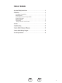
Table of Contents
Important Safety Instructions .............................4
Installation..........................................5
Home Owner Responsibilities ..........................................5
Owner Orientation ...................................................5
Installing Dealer/Contractor Responsibilities...............................5
Equipment Description ...............................................5
Delivery Inspection ..................................................6
System Setup .....................................................10
Testing the Automatic Transfer Switch ..................................11
Controls ...........................................11
Troubleshooting .....................................13
Transfer Switch Schematic Diagram .......................14
Transfer Switch Wiring Diagram ..........................15
Product Specfications .................................16

4 BRIGGSandSTRATTON.COM
Important Safety Instructions
SAVE THESE INSTRUCTIONS - This manual contains important
instructions that should be followed during installation of
the equipment.
Safety Symbols and Meanings
The safety alert symbol indicates a potential personal injury
hazard. A signal word (DANGER, WARNING, or CAUTION) is used
with the alert symbol to designate a degree or level of hazard
seriousness. A safety symbol may be used to represent the type of
hazard. The signal word NOTICE is used to address practices not
related to personal injury.
DANGER indicates a hazard which, if not avoided, will result in
death or serious injury.
WARNING indicates a hazard which, if not avoided, could result
in death or serious injury.
CAUTION indicates a hazard which, if not avoided, could result
in minor or moderate injury.
NOTICE addresses practices not related to personal injury.
The manufacturer cannot possibly anticipate every possible
circumstance that might involve a hazard. The warnings in this
manual, and the tags and decals affixed to the unit are, therefore,
not all-inclusive. If you use a procedure, work method or operating
technique that the manufacturer does not specifically recommend,
you must satisfy yourself that it is safe for you and others. You
must also make sure that the procedure, work method or operating
technique that you choose does not render the equipment unsafe.
Electrical Shock
Read Manual
Save These Instructions
NOTICE Only qualified electricians should attempt installation
of this equipment, which must strictly comply with applicable
codes, standards and regulations.
WARNING Certain components in this product and related
accessories contain chemicals known to the State of California
to cause cancer, birth defects, or other reproductive harm. Wash
hands after handling.
WARNING Shock Hazard. Installing low and high voltage
wire in same conduit could result in death or serious
injury.
• Do not run low and high voltage wire in the same conduit unless
the insulation rating on ALL wiring is rated for 600V. See NEC
for more information.
WARNING Shock Hazard. Failure to properly ground
equipment could cause electrocution resulting in death
or seriousinjury.
• Do not touch bare wires.
• Do not use equipment with worn, frayed, bare or otherwise
damaged wiring.
• Do not handle electrical cords while standing in water, while
barefoot, or while hands or feet are wet.
• If you must work around a unit while it is operating, stand on an
insulated dry surface to reduce shock hazard.
• Do not allow unqualified persons or children to operate or
service equipment.
• In case of an accident caused by electrical shock, immediately
shut down all sources of electrical power and contact local
authorities. Avoid direct contact with the victim.
WARNING Shock Hazard. Equipment contains high voltage
that could cause electrocution resulting in death or
seriousinjury.
• Do not operate this equipment imprudently, carelessly or neglect
its maintenance.
NOTICE Improper treatment of equipment could damage it and
shorten its life.
• Use equipment only for intended uses.
• If you have questions about intended use, ask dealer or contact
Briggs & Stratton Power Products.
• Do not expose equipment to excessive moisture, dust, dirt, or
corrosive vapors.
• Remain alert at all times while working on this equipment. Never
work on the equipment when you are physically or
mentally fatigued.
• If connected devices overheat, turn them off and turn off their
circuit breaker/fuse.
WARNING Shock Hazard. Failure to properly wire equipment could
cause electrocution resulting in death or seriousinjury.
• DO NOT connect the ground conductor to the neutral connection in the
remote module.
• All modules must have a dedicated neutral connection.

5
Installation
We sincerely appreciate your patronage and have made significant
effort to provide for a safe, streamlined and cost-effective
installation. Because each installation is unique, it is impossible
to know of and advise the trade of all conceivable procedures and
methods by which installation might be achieved. Neither could we
know of possible hazards and/or the results of each method
or procedure.
For these reasons, only current licensed electrical professionals
should attempt system installations. Installations must strictly
comply with all applicable codes, industry standards and
regulations.
Your equipment is supplied with this Installation Manual and a
separate Operator’s Manual. These are important documents and
should be retained by the owner after the installation has
been completed.
Every effort has been made to make sure that the information
in this manual is both accurate and current. However, the
manufacturer reserves the right to change, alter or otherwise
improve the system at any time without prior notice.
Home Owner Responsibilities
To help you make informed choices and communicate effectively
with your installation contractor(s), read and understand Owner
Orientation before contracting or starting your
equipment installation.
To arrange for proper installation, contact the store at which you
purchased your equipment, your dealer, or your utility
power provider.
The equipment warranty is VOID unless the system is installed by
licensed electrical professionals.
Owner Orientation
The illustrations provided are for typical circumstances and are
meant to familiarize you with the installation options available with
your system.
Local codes, appearance, and distances are the factors that must
be considered when negotiating with an installation professional.
As the distance from the existing electrical service increases,
compensation in wiring materials must be allowed for. This is
necessary to comply with local codes and overcome electrical
voltage drops.
These factors will have a direct effect on the overall price of your
equipment installation.
Your installer must check local codes AND obtain permits before
installing the system.
• Readandfollowtheinstructionsgiveninthismanual.
• Followaregularscheduleincaringforandusingyour
equipment, as specified in this manual.
Installing Dealer/Contractor Responsibilities
• ReadandobservetheImportantSafetyInstructions.
• Readandfollowtheinstructionsgiveninthismanual.
• Theinstallermayneedtoprovideappropriateratedcontactors
based on loads to be controlled.
• Checkfederal,stateandlocalcodesandauthorityhaving
jurisdiction, for questions on installation.
• Ensuregeneratorisnotoverloadedwithselectedloads.
If you need more information about the transfer switch, call
800-743-4115, between 8:00 AM and 5:00 PM CT.
Equipment Description
The transfer switch is designed to transfer the selected loads found
in normal residential installations when used with the supervisory
contacts provided. The load is connected either to utility power
(normal) or home standby power (generator). The transfer switch
monitors utility and generator voltages and will automatically
connect to the appropriate source ofpower.
These switches make it easy for a licensed electrician to complete
a home standby installation. Service conduit and conductors can
be wired directly from the watt-hour meter to the transfer switch.
A separate disconnect and associated wiring is not required when
installed per applicable federal, state and local codes, standards and
regulations.
Major components of the transfer switch are a 2 pole utility
disconnect circuit breaker, a 2 pole generator disconnect circuit
breaker, a 2 pole double throw transfer switch, control circuit
board, fused utility terminals and interconnecting wiring. The
control board also has two inputs for current transformers that
sense generator current. These components are housed in a
NEMA 3R enclosure that is suitable for both indoor and outdoor
installations.
The transfer switch is solenoid-operated from utility or generator
inputs and contain suitable mechanical and electrical interlock
switches to eliminate the possibility of connecting the utility service
to the generator output. It has ratings capable of switching full
utility power into the residence. In addition, a manual override lever
is provided for the transfer function.
The control board has active circuits sensing utility and generator
voltages. It creates a signal for generator start-up, switch transfer
and retransfer when utility is restored. The control board also
contains red and green LED’s indicating the power sources available
and two relay operated contacts that provide supervisory control of
external loads.

6 BRIGGSandSTRATTON.COM
Delivery Inspection
After opening the carton, carefully inspect the transfer
switch components for any damage that may have occurred
duringshipment.
If loss or damage is noted at time of delivery, have the person(s)
making delivery note all damage on the freight bill and affix his
signature under the consignor’s memo of loss or damage. If loss
or damage is noted after delivery, contact the carrier for claim
procedures. Missing or damaged parts are not warranted.
Shipment contents:
• Automatictransferswitch
• Installationandoperator’smanuals
• Currenttransformers(2)
To be supplied by installer:
• Connectingwireandconduit
• Variousspecialtytools/equipment
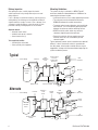
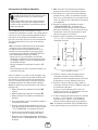
Mounting Guidelines
The system circuitry is enclosed in a NEMA Type 3R
enclosure suitable for indoor/outdoor use. Guidelines for
mounting the enclosure include:
• Installenclosureonafirm,sturdysupportingstructure.
• Theenclosuremustbeinstalledwithminimum
NEMA3R hardware for conduit connections.
• Topreventswitchcontactdistortion,levelandplumb
the enclosure. This can be done by placing washers
between the enclosure and the mounting surface.
• NEVERinstalltheswitchwhereanycorrosive
substance might drip onto the enclosure.
• Protecttheswitchatalltimesagainstexcessive
moisture, dust, dirt, lint, construction grit and
corrosivevapors.
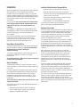
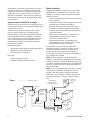
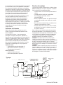
Typical automatic transfer switch installations are depicted
below. It is best if the transfer switch is mounted near
the utility meter, either inside or outside. Discuss layout
suggestions/ changes with the owner before beginning the
system installation process.
Main
Distribution
Panel
Transfer
Switch
Hot Water
Heater
Air
Conditioner
Contactor
Disconnect Switch
Generator
Watt -
Hourmeter
Branch
Circuits
Emergency Branch
Circuits
— — — — — — Control Wiring
Emergency
Load
Center
Main
Distribution
Panel
Transfer Switch
w/ Service
and Generator
Disconnect
Hot Water
Heater
Air
Conditioner
Generator
Watt -
Hourmeter
— — — — — — Control Wiring
Disconnect Switch
Contactor
Branch Circuits
Typical
Alternate

7
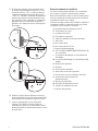
Power Wiring Interconnections
All wiring must be the proper size, properly supported
and protected by conduit. All wiring should be done per
applicable federal, state and local codes, standards and
regulations. Obey wire type and torque specifications printed
on the terminal blocks and neutral/ground connector.
Approved for copper and aluminum conductors.
Complete the following connections between the transfer
switch, main distribution panel, utility power and generator.
Use installer-supplied 300VAC or greater wire that complies
with Table 310.16 in the National Electric Code. Apply the
necessary correction factors and wire size calculations.
1. Set generator’s circuit breaker to OFF (open) position.
2. Set generator’s system switch to OFF position and
remove 15 Amp fuse from system control panel.
3. Turn off utility power to the standby generator and
transfer switch.
4. Connect utility service to transfer switch’s utility
disconnect circuit breaker terminals marked
“UTILITYCONNECTION”.
5. Connect utility service neutral to transfer switch
neutralterminal.
6. Connect main distribution panel feeder
conductors to transfer switch terminals marked
“LOADCONNECTION”.
7. Connect main distribution panel neutral conductor to
transfer switch neutral terminal.
8. Connect main distribution panel ground conductor to
transfer switch “GND” terminal.
Assure grounding electrode conductor is connected and
bonded per applicable federal, state and local codes,
standards and regulations.
9. Connect feeder conductors from transfer switch
breaker “GENERATOR CONNECTION” terminals to
generator circuit breaker LINE1 and LINE2 terminals.
Each conductor must pass through hole of current
transformer before making connection.
10. Plug current transformer leads into “CT1” and “CT2”
terminals on transfer switch control board.
11. Connect conductor from transfer switch neutral
terminal to generator NEUTRAL terminal.
Observe generator control panel labeling for
terminalidentification.
12. Connect conductor from transfer switch “GND” terminal
to generator control panel “GROUND” terminal.
Assure generator equipment grounding conductor is
connected per applicable federal, state and local codes,
standards and regulations.
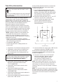
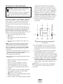
13. Connect the transfer switch “UTILITY 240 VAC”
terminals to generator’s “240 VAC” terminals
using installer supplied 300VAC or greater
wire, minimum #14 AWG conductors via
two-poleconnector supplied with generator.
NOTICE Before drilling conduit entry holes, or any other holes,
cover and protect the switch and electronics to prevent dirt and
metal fragments from entering the mechanical and electrical
components. Failure to do so may result in damage or malfunction
of the switch.
NOTICE Use a vacuum to clean any dirt or metal shavings inside
the transfer switch. Do not use a blower or compressed air to clean
the inside of the transfer switch because debris may become lodged
in the electrical and mechanical components causing damage or
malfunction.
NOTICE Improper installation can cause damage to the
circuit boards and shorten their life. Installing circuit
boards in live circuits will damage the board and is not
covered by warranty. ALWAYS disconnect ALL sources of
power prior to servicing.
• Remove all power prior to installing this equipment.
Failure to do so could cause internal damage to the board
when making electrical connections.
• Turn generator to OFF position.
• Turn off utility power to the standby generator and
transfer switch.
WARNING Battery posts, terminals and related
accessories contain lead and lead compounds, chemicals
known to the State of California to cause cancer and
reproductive harm. Wash hands after handling.
33
240V
11
22
44
11
22
44
120V
120V
0
Neutral
Ground
To Transfer Switch
Line 1 Neutral
Ground
Line 2
Circuit
Breaker
WARNING Shock Hazard. Installing low and high voltage
wire in same conduit could result in death or serious
injury.
• Do not run low and high voltage wire in the same conduit unless
the insulation rating on ALL wiring is rated for 600V. See NEC
for more information.

8 BRIGGSandSTRATTON.COM
14. Connect “T/R” and “GND” terminals on transfer switch
control board (B) to the generator’s control panel (A)
“TxRx” and “TxRx GND” terminals using #18 AWG
twisted pair conductors, no greater than 200 ft in
length, 300 volt 75°C-90°C via ten-pole connector or
eight pin terminal.
15. Tighten all wire connections/fasteners to proper torque.
See label inside transfer switch enclosure for proper
torque values.
Supervisory Control Wiring
An air conditioner can be used with the supervisory contacts
on either terminals A-A or B-B. Terminals A-A can only be
used with supervisory control. Large loads can only be used
with contactor control on terminals B-B. Examples of each
system are described below.
1. The terminal strip on the transfer switch control board
has four connections for customer use. There are two
sets of “Normally Closed” contacts available. They will
be activated when generator power is required. These
can be used for supervisory control of large connected
loads on generator. Loads will be allowed to operate if
there is enough generator poweravailable.
For installer convenience, there are two wireways provided to
help keep supervisory load wires organized.
2. Terminals “A-A” on transfer switch control board
are rated for 24VAC. Connect these contacts in
series between air conditioner thermostat and air
conditionercontactor.
3. Terminals “B-B” on transfer switch control board are
rated for 1 Amp 125 VAC. When connected with an
installer supplied contactor, it can be used to control
a large load, such as an electric hot water heater.
Contacts are connected in series with the contactor
control circuit.
4. Tighten all wire connections/fasteners to proper torque.
See label inside transfer switch enclosure for proper
torquevalues.
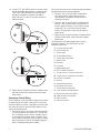
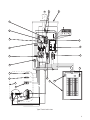
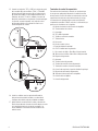
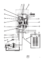
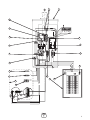
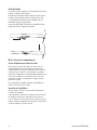
The illustration on the following page shows a typical
completed installation. Your actual layout will vary.
Illustration callouts are:
A - From utility watt-hour meter
B - Current transformers
C - Transfer switch
D - T/R and GND to Generator
E - Transfer switch control board
F - Neutral terminal
G - Neutral bus
H - Ground bus
J - Main distribution panel
K - UTILITY 240VAC to Generator
L - Two pin connector or Two pin terminal block
M - Ten pin connector or Eight pin terminal block
N - Generator circuit breaker
P - Generator
R - Generator Neutral terminal
S - Generator Ground terminal
T - Transfer switch ground terminal
U - Load connection to distribution panel
V - Generator disconnect circuit breaker
W - Utility disconnect circuit breaker
X - Utility connection
Y - Generator connection
A
B
A
B
OR

9
Typical Transfer Switch shown
G
LINE1
LINE2
N
240
VAC
L
1
L
2
N
G
L
1
L
2
N
OR
A
D
E
F
G
T
S
H
U
M
Y
P
N
K
W
J
V
R
CB
L
X
L
M

10 BRIGGSandSTRATTON.COM
System Setup
You must perform the following before operating the system:
• Ifgeneratorisinstalledinanarearegularlysubjectedto
temperatures below 40°F (4°C), select a 50 second warm up
time by moving jumper JP2 (C) installed on transfer switch
control board from ‘20’ position to ‘50’position.
• SettheDPSW1(A)andDPSW2(B)dipswitchesonthe
transfer switch control board to match the kW rating of the
standby generator, as described in SettingDipswitches.
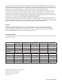
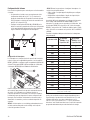
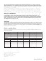
Setting Dipswitches
Dipswitches are used to adjust control board operation based
on generator capacity. DPSW1 and DPSW2 switches are set to
correspond to total system kW rating. Dipswitch DPSW1 (A) has
units of 1,000 watts; Dipswitch DPSW2 (B) has units of
10,000 watts.
Set dipswitches with utility and generator power removed from
the transfer switch to ensure proper control system operation.
If dipswitches are set when power is present at transfer switch,
a power reset needs to be performed before the new dipswitch
settings will take effect. Power reset is when all power is removed
from the transfer switch and then reintroduced after 30 seconds.
NOTICE An FC_8 will occur on standby generator control board if
dipswitches are not properly established as noted above.
The “On” position for the dipswitches is the switch number ON
THE TRANSFER SWITCH CONTROL BOARD, not on the switch. For
example, for an 18,000 watt generator, set DPSW2 dipswitch 10 to
“On” position. Set DPSW1 dipswitch 8 to “On” position. 10,000 plus
8000 equals 18,000 watts.
Set only one switch to “On” position
on DPSW1 andDPSW2.
Refer to following chart for proper switch selection(s).
NOTICE
Air density is less at high altitudes, resulting in less
available engine power. Specifically, engine power will decrease 3.5%
for each 1,000 feet (300 meters) above sea level and 1% for each 10°
F (5.6°C) above 77°F (25°C). Generators located in these conditions
must have the transfer switch programmed appropriately for this
power decrease.
kW Rating
of
Generator
DPSW
#1 “ON”
Position
DPSW
#2 “ON”
Position
7kW 7 0
8kW 8 0
9kW 9 0
10kW* 0 10
11kW* 1 10
12kW 2 10
13kW* 3 10
14kW 4 10
15kW 5 10
16kW 6 10
17kW 7 10
18kW 8 10
19kW 9 10
20kW 0 20
30kW 0 30
45kW 5 40
48kW 8 40
50kW 0 50
60kW 0 60
* For generators with a rating that includes 500 Watts, round down to
next lowest rating
(example: 13.5 kW set to 13kW)
A
B
NOTICE Use extreme caution when setting dipswitches or
damage to control board will result.
• Use a pencil or small piece of plastic to set the dipswitch.
• NEVER use a screwdriver or any type of metal object to
set dipswitches.
A
B

11
Testing the Automatic Transfer Switch
Turn the utility service disconnect circuit breaker feeding the
transfer switch contactor to the OFF position. The system’s
automatic sequence described below will initiate. To return to utility
power, turn the utility service disconnect circuit breaker to the
ON position.
Utility Fail
The generator senses when utility voltage is below 70percent of
nominal. Engine start sequence is initiated after 6second time
delay.
Engine Warm-Up
Time delay to allow for engine warm-up before transfer. Use jumper
on transfer switch control board to select delay of
20seconds or 50 seconds.
Transfer
Transfer from utility to generator supply occurs after voltage is
above set levels. The transfer switch control board LED lights will
change from green (utility) to red (generator) and the Symphony II
status light will change blink status from Blink Blink_Pause_Blink
Blink to Blink_Pause_Blink. Minimum engine run time is 5 minutes
after transfer.
Load Management
Five minutes after transfer to generator power, the remote modules
energize connected load(s) if generator power is available, starting
with the highest priority (1) through the lowest priority (8). There is
a 10 second delay between each sequential activation.
The P1 through P8 LED’s (A) on the Symphony II control board will
illuminate to show loads being added.
Loads connected to remote modules set to priorities 9 and 10
remain off for the duration of a utility power outage.
Utility Pickup
Voltage pickup level is 80 percent of nominal voltage.
Retransfer
Retransfer from generator to utility power is approximately 10
seconds after utility voltage supply is above pickup level and
minimum run time is completed. All remote module(s) will remain
OFF for five minutes after the power transfer.
Engine Cool Down
Engine will run for 60 seconds after retransfer.
Controls
Other than a Manual Override lever, there are no operator controls
because this is an automatic transfer switch. The manual override
is to be used only by licensed professionals. Information on handle
use can be obtained by calling Technical Service at 800-743-4115.
Operation
To select automatic transfer operation, do the following:
1. In transfer switch, set utility disconnect circuit breaker
to “ON” position.
2. In transfer switch, set generator disconnect circuit
breaker to “ON” position.
3. Install 15 Amp fuse in generator’s control panel.
4. Set generator’s circuit breaker to “ON” position.
5. Set generator’s system switch to “AUTO” position.
The system will now be in automatic operation mode.
When the generator is providing power to the transfer
switch, the transfer switch control board is constantly
monitoring generator power. If the air conditioner is called
to run, and there is sufficient generator power available,
the controller will close contacts “A-A” to air conditioner
contactor. Contacts “B B” will open before contacts A-A
close. If loads are too great for the generator, contacts A-A
and/or B-B will open. When air conditioning is not needed,
A-A will open. If enough power is available, B-B will close.
Enclosure Door
To open door, press the spring-load door lock to the right
and pull down on the door.
To close and latch door, push door closed against enclosure.
While in this position, push door upwards. This will cause
spring-load door lock to engage and latch door in place.
Enclosure door MUST be closed and latched at all times
except when system is being serviced.
WARNING Shock Hazard. Equipment contains high voltage
that could cause electrocution resulting in death or
serious injury.
• Testing must only be performed by qualified personnel.
• Do not operate this equipment imprudently, carelessly or neglect
its maintenance.

12 BRIGGSandSTRATTON.COM
Maintenance
The transfer switch is designed to be maintenance free under
normal usage. However, inspection and maintenance checks
should be made on a regular basis. Maintenance will consist
mainly of keeping the transfer switch clean.
Visual inspections should be done at least once a month.
Access to transfer switch must not be obstructed. Keep
3feet (92 cm) clearance around transfer switch. Check
for an accumulation of dirt, moisture and/or corrosion
on and around the enclosure, loose parts/hardware,
cracks and/or discoloration to insulation, and damaged or
discoloredcomponents.
Exercise the transfer switch at least once every three months
as described in Testing the Automatic Transfer Switch unless
a power outage occurs and home generator system has gone
through an automatic sequence. Allow generator to run for at
least 30 minutes.
Contact a licensed electrical professional to inspect and clean
the inside of the enclosure and other components of your
home generator system at least once a year.
When Calling for Assistance
You must have the Model Number and Serial Number from
the unit ID label at hand if it is necessary to contact a local
service center regarding service or repair of this unit. Obtain
this information from the unit ID label located on or inside the
enclosure.
To contact Briggs & Stratton call 800-743-4115, between
8:00 AM and 5:00 PM CT.
Installation Inspection
Before placing the system into service, inspect the entire
installation carefully.

13
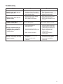
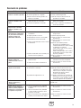
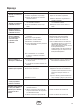
Troubleshooting
Problem Cause Correction
Au tomatic transfer switch does not
transfer to generator
1. Generator breaker open.
2. Generator voltage not acceptable.
3. Generator disconnect circuit breaker
open in transfer switch.
1. Reset generator circuit breaker.
2. Refer to generator manual.
3. Reset generator disconnect circuit
breaker in transfer switch.
Au tomatic transfer switch does not
transfer to utility
1. Utility disconnect circuit breaker
open in transfer switch.
2. Utility voltage not acceptable.
1. Reset utility disconnect circuit
breaker in transfer switch.
2. Wait for utility voltage to return
tonormal.
Ge nerator is still running after switch
transfers to utility power
Engine cool down period. Engine should stop after 1 minute.
Ge nerator or supervised loads (air
conditioner, etc.) are operating
improperly when generator is
supplyingpower
1. A-A or B-B contacts not
operatingcorrectly.
2. Too much load on generator.
3. Current transformer not connected.
4. Broken current transformer.
1. Check A-A or B-B contacts for
proper operation and/or check
control wiring to external load.
2. Decrease load to generator.
3. Plug CT connectors into
controlmodule.
4. Contact local authorized
servicecenter.
Ge nerator is still running after utility
power is restored
1. Minimum engine run time has
notelapsed.
2. Fuse(s) in transfer switch
isdefective.
1. Wait five minutes for transfer switch
to retransfer to utility power.
2. Check fuse(s) and replace
ifnecessary.

14 BRIGGSandSTRATTON.COM
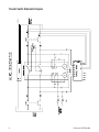
Transfer Switch Schematic Diagram
MAIN
BREAKER PANEL

15
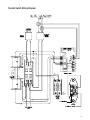
Transfer Switch Wiring Diagram
MAIN
BREAKER
PANEL

16 BRIGGSandSTRATTON.COM
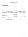
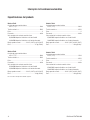
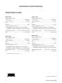
Automatic Transfer Switch
Product Specfications
Model 071045
Rated Maximum Load Current
a 25°C (77°F)* ..............................................................100 Amps
Rated AC Voltage. ..............................................................250 Volts
Poles ............................................................................................... 2
Frequency ................................................................................60 Hz
Fault Current Rating ..........22,000 RMS Symmetrical Amperes on Utility Side
................................. 10,000 RMS Symmetrical Amperes on Generator Side
Normal Operating Range ...............-28.8°C (-20°F) to 40°C (104°F)
Weight ........................................................................28 kg (63 lbs)
Model 071046
Rated Maximum Load Current
a 25°C (77°F)* ..............................................................200 Amps
Rated AC Voltage. ..............................................................250 Volts
Poles ............................................................................................... 2
Frequency ................................................................................60 Hz
Fault Current Rating ..........25,000 RMS Symmetrical Amperes on Utility Side
................................. 10,000 RMS Symmetrical Amperes on Generator Side
Normal Operating Range ...............-28.8°C (-20°F) to 40°C (104°F)
Weight ........................................................................28 kg (63 lbs)
This transfer switch is a UL Listed device.
Model 071044
Rated Maximum Load Current
a 25°C (77°F)* ..............................................................200 Amps
Rated AC Voltage. ..............................................................250 Volts
Poles ............................................................................................... 2
Frequency ................................................................................60 Hz
Fault Current Rating ..........25,000 RMS Symmetrical Amperes on Utility Side
................................. 10,000 RMS Symmetrical Amperes on Generator Side
Normal Operating Range ...............-28.8°C (-20°F) to 40°C (104°F)
Weight ........................................................................28 kg (63 lbs)
Model 071069
Rated Maximum Load Current
a 25°C (77°F)* ..............................................................150 Amps
Rated AC Voltage. ..............................................................250 Volts
Poles ............................................................................................... 2
Frequency ................................................................................60 Hz
Fault Current Rating ..........25,000 RMS Symmetrical Amperes on Utility Side
................................. 10,000 RMS Symmetrical Amperes on Generator Side
Normal Operating Range ...............-28.8°C (-20°F) to 40°C (104°F)
Weight ........................................................................28 kg (63 lbs)

Manual de instalación
100/150/200 Amperios Interruptor de
transferencia automática
con módulo de control de energía eléctrica de CA™
Preguntas?
La ayuda es justa un momentolejos!
Llamada: Línea Directa de generador de hogar
800-743-4115 M-F 8-5 CT

2 BRIGGSandSTRATTON.COM
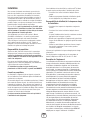
Gracias por comprar este conectador automático de Briggs & Stratton®. Este producto está diseñado para utilizarse con generadores de
reserva domésticos específicos y puede no funcionar con generadores o módulos remotos producidos por otros fabricantes. Recurra a un
electricista profesional cualificado para determinar si este equipo se puede utilizar con equipo fabricado por terceros. Si se utiliza y mantiene
de acuerdo con las instrucciones de este manual, su sistema le proporcionará muchos años de funcionamiento fiable.
Este manual contiene información de seguridad para que usted conozca los peligros y riesgos propios de este sistema y cómo evitarlos.
Se ha realizado el máximo esfuerzo para que la instalación resulte segura, sencilla y económica. Debido a que cada instalación es única,
es imposible conocer y recomendar todos los procedimientos y métodos posibles para efectuarla. No conocemos todos los riesgos y/o
resultados posibles de cada método o procedimiento existente. Es importante que lea y comprenda perfectamente estas instrucciones antes
de intentar instalar o utilizar este equipo. Guarde estas instrucciones para futuras consultas.
Este conectador y los módulos remotos opcionales deben ser instalados por un profesional antes de utilizarlos. Consulte la sección de
instalación de este manual y las instrucciones de instalación que vienen con los módulos remotos. Los conectadores y los módulos remotos
sólo deben ser instalados por electricistas con licencia. Las instalaciones deben cumplir estrictamente la totalidad de los códigos, estándares
y regulaciones federales, estatales y locales vigentes. El instalador debe seguir las instrucciones detalladamente.
Ubicación
Nunca debe ir demasiado lejos para encontrar el soporte y servicio de Briggs & Stratton para su sistema. Consulte las Páginas
Amarillas. Existen múltiples distribuidores de servicio autorizados que ofrecen un servicio de calidad. También puede comunicarse
con el Servicio Técnico por teléfono al 800-743-4115 entre 8:00 a. m. y 5:00 p. m. Hora del Centro; o bien, busque un distribuidor en
BRIGGSandSTRATTON.COM, donde se incluye una lista de distribuidores autorizados.
Para futuras consultas
Llene la siguiente información y conserve su factura para facilitar la identificación de la unidad en caso de que surjan problemas relacionados
con la compra en el futuro.
Copyright © 2013. Briggs & Stratton Power Products Group, LLC
Milwaukee, WI, USA. Reservados todos los derechos.
Briggs & Stratton Power Products es una marca
registradas de Briggs & Stratton Corporation
Milwaukee, WI, USA
Conectador Módulo remoto Módulo remoto Módulo remoto Módulo remoto
Número de modelo
Versión
Número de serie
Fecha de compra
PRIORIDAD N/A
Módulo remoto Módulo remoto Módulo remoto Módulo remoto Módulo remoto Módulo remoto

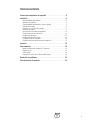
3
Tabla de contenido
Instrucciones importantes deseguridad ......................4
Instalación ..........................................5
Responsabilidades del propietario.......................................5
Orientación al propietario .............................................5
Re sponsabilidades del distribuidor / técnicoinstalador ......................5
Descripción del equipo ...............................................5
Inspección en el momento de la entrega..................................7
Directrices de montaje................................................7
Interconexión de los cables de alimentación..............................12
Terminales de control de supervisión ...................................13
Configuración del sistema ............................................15
Configuración del módulo remoto......................................16
Prueba del conectador automático .....................................16
Pr ueba del sistema de gestión de energíaSymphony II .....................17
Controles . . . . . . . . . . . . . . . . . . . . . . . . . . . . . . . . . . . . . . . . . .18
Funcionamiento .....................................18
Monitor de alimentación Symphony™ II (opcional) ........................18
Puerta de la caja ...................................................18
LED de estado .....................................................19
Indicadores de estado de los LED del módulo remoto ......................20
Resolución de problemas...............................22
Especificaciones del producto............................23

4 BRIGGSandSTRATTON.COM
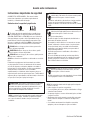
Instrucciones importantes deseguridad
GUARDE ESTAS INSTRUCCIONES - Este manual contiene
instrucciones importantes que se deben seguir durante la
instalación y el mantenimiento delequipo.
Símbolos sobre la seguridad y significados
El símbolo de alerta de seguridad indica un posible riesgo
para su integridad física. Se utiliza una palabra de señalización
(PELIGRO, ADVERTENCIA o ATENCIÓN) junto con el símbolo de
alerta para designar un grado o nivel de gravedad de riesgo. Se
puede utilizar un símbolo de seguridad para representar el tipo
de riesgo. La palabra de señalización AVISO se utiliza para hacer
referencia a una práctica no relacionada con una lesión física.
PELIGRO indica un riesgo que, de no evitarse, provocará la
muerte o lesiones de gravedad.
ADVERTENCIA indica un riesgo que, de no evitarse, podría
provocar la muerte o lesiones de gravedad.
ATENCIÓN indica un riesgo que, de no evitarse, podría provocar
lesiones leves o moderadas.
AVISO hace referencia a una práctica no relacionada con una lesión
física.
El fabricante no puede prever toda circunstancia que conlleve
un riesgo potencial. Por tanto, las advertencias de este manual,
así como las etiquetas y calcomanías adheridas a la unidad, no
incluyen todos los riesgos posibles. Si utiliza un procedimiento,
método de trabajo o técnica de uso no recomendado
específicamente por el fabricante, deberá asegurarse de que es
seguro tanto para usted como para otras personas. También deberá
asegurarse de que el procedimiento, método de trabajo o técnica de
uso que elija no hace que el equipo sea inseguro.
Guarde estas instrucciones
Descarga eléctrica
Lea el manual
AVISO La instalación de este equipo debe cumplir estrictamente
la totalidad de los códigos, estándares y regulaciones vigentes,
por lo que sólo debe ser llevada a cabo por un electricista
cualificado.
ADVERTENCIA Determinados componentes en este producto
y los accesorios relacionados contienen sustancias químicas
declaradas cancerígenas, causantes de malformaciones, y otros
defectos congénitos por el Estado de California. Lávese las
manos después de manipular estos elementos.
ADVERTENCIA Peligro de descarga. La instalación de un
cable de baja y alta tensión en el mismo conducto podría
provocar lesiones graves o incluso la muerte.
• No tienda un cable de baja y alta tensión en el mismo conducto
a menos que el valor nominal de aislamiento en TODO el
cableado sea de 600 V. Para obtener más información, consulte
el NEC.
ADVERTENCIA Peligro de descarga. Una conexión a tierra
defectuosa del equipo podría provocar electrocución, así
como lesiones graves o incluso la muerte.
• No toque los cables pelados.
• No utilice el equipo con cables desgastados, deshilachados o
deteriorados de cualquier otra forma.
• No manipule los cables eléctricos si se encuentra en una zona
húmeda, está descalzo o tiene las manos o los piesmojados.
• Si tiene que trabajar junto a una unidad en funcionamiento,
manténgase en una superficie aislada y seca para reducir el
riesgo de descarga eléctrica.
• No permita que personas no cualificadas o niños utilicen o
reparen el equipo.
• En caso de accidente provocado por una descarga eléctrica,
desconecte inmediatamente todos los suministros de energía
eléctrica y póngase en contacto con las autoridades locales.
Evite el contacto directo con la víctima.
ADVERTENCIA Peligro de descarga. El equipo contiene alta
tensión que podría provocar electrocución, así como
lesiones graves o incluso la muerte.
• No utilice este equipo de un modo imprudente, sin tener cuidado
o con negligencia en cuanto a su mantenimiento.
AVISO Un tratamiento inadecuado del equipo podría estropearlo
y acortar su vida útil.
• Utilice el equipo sólo para los usos previstos.
• En caso de dudas sobre su uso, diríjase al distribuidor o a Briggs
& Stratton Power Products.
• No exponga el equipo a un exceso de humedad, polvo, suciedad
o vapores corrosivos.
• Manténgase alerta en todo momento cuando utilice este equipo.
Nunca lo utilice ni manipule en condiciones de fatiga física o
mental.
• Si se calientan excesivamente los dispositivos conectados,
apáguelos y abra sus interruptores o quite sus fusibles.
La page charge ...
La page charge ...
La page charge ...
La page charge ...
La page charge ...
La page charge ...
La page charge ...
La page charge ...
La page charge ...
La page charge ...
La page charge ...
La page charge ...
La page charge ...
La page charge ...
La page charge ...
La page charge ...
La page charge ...
La page charge ...
La page charge ...
La page charge ...
La page charge ...
La page charge ...
La page charge ...
La page charge ...
-
 1
1
-
 2
2
-
 3
3
-
 4
4
-
 5
5
-
 6
6
-
 7
7
-
 8
8
-
 9
9
-
 10
10
-
 11
11
-
 12
12
-
 13
13
-
 14
14
-
 15
15
-
 16
16
-
 17
17
-
 18
18
-
 19
19
-
 20
20
-
 21
21
-
 22
22
-
 23
23
-
 24
24
-
 25
25
-
 26
26
-
 27
27
-
 28
28
-
 29
29
-
 30
30
-
 31
31
-
 32
32
-
 33
33
-
 34
34
-
 35
35
-
 36
36
-
 37
37
-
 38
38
-
 39
39
-
 40
40
-
 41
41
-
 42
42
-
 43
43
-
 44
44


Simplicity 040481-00 Guide d'installation
- Catégorie
- Groupes électrogènes
- Taper
- Guide d'installation
dans d''autres langues
Documents connexes
-
Simplicity 040411-00 Guide d'installation
-
Simplicity 071044-01 Guide d'installation
-
Simplicity 040481-00 Manuel utilisateur
-
Briggs & Stratton Split 400 Amp Guide d'installation
-
-
-
-
Simplicity 040455-00 Manuel utilisateur
-
-
Simplicity 040475-00 Manuel utilisateur