Asco Clarifiair Filter System Modulair 107 112 Le manuel du propriétaire
- Taper
- Le manuel du propriétaire

GB
MONTAGE
●●
●●
●
A placer à proximité du point d'utilisation
●●
●●
●
Position verticale (inclinaison maxi 5°)
●●
●●
●
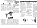
Les composants de l'ensemble de
traitement de l'air Clarifiair se raccor-
dent suivant le sens de circulation
gauche-droite (semblable à celui de la
symbolisation). Le sens d'écoulement
de l'air est indiqué en face avant par
une flèche. (voir fig. 1)
●●
●●
●
Possibilité de montage inversé, avec
circulation droite-gauche, en retournant
les appareils et déplacer de 180°, en
face avant, les protecteurs de cuves et
manomètre (pré-filtre/régulateur).
●●
●●
●
Fixation frontale directe ou par équerres
latérales (voir notice MS-P710-1)
●●
●●
●
Visualisation du niveau des condensats:
-par la petite ouverture en face avant
sur protecteur de cuve (voir fig. 2)
- par cuve transparente (version cuve
polycarbonate)
●●
●●
●
Suivant la version choisie, les filtres
sont équipés de purges semi-automati-
ques ou automatiques ou manuelles
(en option)
ENTRETIEN
●●
●●
●
Démontage/remontage des cuves et
protecteurs (voir notice MS-P710-1)
●●
●●
●
S'ils sont colmatés, veuillez procéder au
remplacement des éléments filtrants 5 µm
et 0,01 µm
●●
●●
●
Composant proposé en pièces de
rechange:
- Elément filtrant 5 µm (couleur blanc),
code 978 02 070 (Modulair 107)
code 978 01 731 (modulair 112)
- Cartouche filtrante 0,01 µm,
code 978 00 740 (Modulair 107)
code 978 01 005 (modulair 112)
●●
●●
●
Toutes les autres pièces sont proposées
en pièces de rechange
(voir PR-P710-1 et PR-P710-3)
INSTALLATION
●●
●●
●
Install the system near where the air is
to be used
●●
●●
●
Orientate vertically (max. inclination 5°)
●●
●●
●
The components of the Clarifiair air
treatment system are designed for flow
from left to right (corresponding to the
symbology). The air flow direction is
indicated on the front by an arrow
(see Fig. 1).
●●
●●
●
The system can be arranged for flow
from right to left by reversing the
components and turning the bowl guards
and pressure gauge (prefilter/regulator)
through 180° to face outward.
●●
●●
●
Direct frontal mounting or side mounting
with brackets possible (see leaflet MS-
P710-1).
●●
●●
●
Condensate level visible:
- via the small opening on the front of
the bowl protection (see Fig. 2),
- through the transparent bowl
(polycarbonate bowl version).
●●
●●
●
Depending on the version selected, the
filters are equipped with semi-automatic,
automatic or manual purges (optional).
MAINTENANCE
●●
●●
●
Removal/reinstallation of bowls and pro-
tections (see leaflet MS-P710-1).
●●
●●
●
Replace the 5 µm and 0.01 µm filtering
elements if clogged.
●●
●●
●
The following spare parts are available:
- 5 µm filtering element (white),
code 978 02 070 (Modulair 107)
code 978 01 731 (modulair 112)
- 0.01 µm filtering cartridge,
code 978 00 740 (Modulair 107)
code 978 01 005 (modulair 112)
●●
●●
●
All the other components are available
as spare parts
(see PR-P710-1 and PR-P710-3).
Fig./Abb. 1
Fig./Abb. 2
Niveau maxi
des condensats
Maximum
condensate level
Max. Kondensathöhe
EINBAU
●●
●●
●
Nahe der Einsatzstelle montieren.
●●
●●
●
Vertikale Lage (max. Neigung: 5°).
●●
●●
●
Die Komponenten der Wartungseinheit
Clarifiair werden in Durchflußrichtung von
links nach rechts montiert (wie angezeigt).
Die Durchflußrichtung ist auf der Vorder-
seite mit einem Pfeil angegeben
(siehe Abb. 1).
●●
●●
●
Die Druckluftversorgung kann wahlweise
auch von rechts nach links erfolgen. Dazu
werden die Geräte gedreht und die
Schutzkörbe und Manometer (Vorfilter/
Druckregler) um 180° versetzt.
●●
●●
●
Direkte Befestigung von vorne oder seit-
liche Besfetigung mit Haltewinkeln (siehe
MS-P710-1).
●●
●●
●
Füllstandsanzeige für Kondensat:
- über die kleine Öffnung an der Vor-
derseite des Schutzkorbes (siehe Abb. 2)
oder
- mit transparentem Behälter (Version mit
Behälter aus Polykarbonat).
●●
●●
●
Die Filter sind je nach Version mit halb-
automatischem, automatischem oder
handbetätigtem Ablaßventil ausgestattet
(Option).
WARTUNG
●●
●●
●
Montage/Demontage der Behälter und
Schutzkörbe (siehe MS-P710-1).
●●
●●
●
Die Filterelemente mit einer Filterfeinheit
von 5 µm oder 0,01 µm sind auszutau-
schen, sobald sie sich zugesetzt haben.
●●
●●
●
Die folgenden Elemente sind erhältlich:
- Filterelement mit 5 µm (weiß),
Bestell-Code 978 02 070 (Modulair 107)
Bestell-Code 978 01 731 (modulair 112)
- Filtereinsatz mit 0,01 µm,
Bestell-Code 978 00 740 (Modulair 107)
Bestell-Code 978 01 005 (modulair 112)
●●
●●
●
Alle anderen Komponenten stehen eben-
falls als Ersatzteile zur Verfügung
(siehe PR-P710-1 und PR-P710-3).
DE
FR
(383 47 43)
MS-P710-2c
GENERALITES
L'ensemble Clarifiair permet d'obtenir un
niveau élevé de filtration
●●
●●
●
des particules solides (0,01 µm)
●●
●●
●
des aérosols d'huile et d'eau (0,01 ppm)
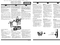
Pour réaliser cette fonction, l'ensemble est
constitué d'un préfiltre ou préfiltre/régulateur
5 µm et d'un filtre submicronique Clarifiair 0,01 µm
Dans le cas d'applications en ambiances très
chargées en eau, huile ou poussières et afin
d'éviter la saturation trop rapide de l'élément
filtrant 5 µm et cartouche 0,01 µm, il est re-
commandé que l'ensemble Clarifiair soit pré-
cédé d'un filtre d'entrée avec seuil de filtra-
tion 25 ou 50 µm
(à commander séparement ainsi qu'un lot d'as-
semblage standard: voir ci-dessous)
GENERAL
CLARIFIAIR systems provide a high level of
filtration:
●●
●●
●
for solid particles (0.01 µm),
●●
●●
●
for oil and water aerosols (0.01 ppm).
The system features a prefilter or prefilter/
regulator of 5 µm capacity and a Clarifiair
submicronic filter of 0.01 µm capacity. In
applications where the atmosphere is heavily
laden with water, oil or dust, it is
recommended to place a 25 or 50 µm
capacity filter upstream of the Clarifiair
system to avoid rapid saturation of the 5 µm
filtering element and the 0.01 µm cartridge.
(standard assembly kit: see below)
Mise en service et entretien - Installation and maintenance - Einbau und Wartung
ENSEMBLE FILTRE CLARIFIAIR
CLARIFIAIR FILTER SYSTEM
FILTEREINHEIT CLARIFIAIR
FR
GB
DE
25/50 µm
0,01 µm
5 µm
Ensemble Clarifiair
Clarifiair system
Filtereinheit Clarifiair
Modulair 107
343 04 001
Modulair 112
343 03 001
SPECIFICATIONS GENERALES
D'UTILISATION
●●
●●
●
Fluide controlé : air comprimé ou gaz
neutres
●●
●●
●
Température ambiante : +1,5°C à + 50°C
●●
●●
●
Pression maxi d'utilisation : ne pas
dépasser la pression suivante
(en fonction de la température ambiante)
16 bar à 23°C / 10 bar à 50°C
●●
●●
●
Composant avec purge automatique :
10 bar maxi
●●
●●
●
Recommandation d'utilisation :
Ne pas dépasser le débit:
- 700 l/min ou 11,7 dm
3
/
s
(Modulair 107)
- 1050 l/min ou 17,5 dm
3
/
s
(Modulair 112)
et un ∆P maxi de 0,350 bar afin de
conserver les performances maximales de
la cartouche de filtration.
GENERAL OPERATING
SPECIFICATION
●●
●●
●
Fluid: compressed air or neutral gas
●●
●●
●
AMBIENT TEMPERATURE: +1.5°C to + 50°C
●●
●●
●
Max. pressure: do not exceed the following
pressure (depending on the ambient
temperature)
16 bar to 23°C / 10 bar to 50°C
●●
●●
●
Maximum pressure with automatic purge
fitting: 10 bar.
●●
●●
●
Utilisation recommendation:
Do not exceed the following flow rates:
- 700 l/min or 11.7 dm
3
/
s
(Modulair 107)
- 1050 l/min or 17.5 dm
3
/s
(Modulair 112)
and a maximum pressure differential of
0.350 bar so as to retain optimum filtering
cartridge performance.
ALLGEMEINE BETRIEBSDATEN
●●
●●
●
Medium: Druckluft oder neutrale Gase
●●
●●
●
Umgebungstemperatur: +1,5 °C bis +50 °C
●●
●●
●
Max. Betriebsdruck: die folgenden Drücke
dürfen nicht überschritten werden (in Ab-
hängigkeit der Umgebungstemperatur):
16 bar bei 23 °C / 10 bar bei 50 °C
●●
●●
●
Einheit mit automatischem Kondensatab-
laß: max. 10 bar
●●
●●
●
Empfehlung für den Betrieb:
Um die Leistung des Filtereinsatzes sicher-
zustellen, darf ein Durchfluß von
- 700 l/min oder 11,7
dm
3
/
s
(Modulair 107) bzw
-
1050 l/min oder 17,5
dm
3
/
s
(Modulair 112)
bei einem max. ∆P von 0,350 bar nicht
überschritten werden.
ALLGEMEINES
Die Filtereinheit Clarifiair wird insbesondere
dort eingesetzt, wo eine hohe Filterfeinheit
erforderlich ist:
●●
●●
●
bei festen Teilchen (0,01 µm) und
●●
●●
●
bei Öl- und Wasseraerosolen (0,01 ppm).
Die Einheit besteht aus einem Vorfilter oder
einem Vorfilter//Druckregler mit einer Filter-
feinheit von 5 µm und einem Clarifiair-
Feinstfilter mit einer Filterfeinheit von
0,01 µm, um die erwünschte Filterfeinheit zu
erlangen. Im stark wasser-, öl- oder staub-
haltigem Milieu wird empfohlen, die Clarifiair-
Einheit mit einem Vorfilter von entweder
25 µm oder 50 µm zu versehen (der Vorfilter
ist separat zusammen mit einem Standard-
verbindungssatz - siehe unten - zu bestel-
len). Dadurch wird vermieden, daß sich das
Filterelement mit 5 µm oder der Filtereinsatz
mit 0,01 µm zu schnell zusetzen.
MODULAIR 107-112
Les appareils de traitement de l'air Modulair
107 et 112 existent en versions prévues pour
atmosphères explosibles sous forme de
gaz, vapeurs, brouillard et poussiéreuses
(directive
ATEX 94/9/CE) : leur mise en
service et entretien se font selon les indications
ci-dessous.
Air service equipment of the Modulair 107
and 112 range exists in versions intended
for use in potentially explosive
atmospheres caused by gases, vapours,
mists an/or dusts (ATEX directive 94/9/
EC). Startup and maintenance are to be
performed as detailed below.
Die Geräte zur Druckluftaufbereitung des
Typs Modulair 107 und 112 stehen in
verschiedenen Versionen für den Einsatz
in explosionsfähigen Atmosphären, die
durch Gase, Dämpfe, Nebel oder Staub
verursacht werden (ATEX-Richtlinie 94/9/
EG), zur Verfügung: Die Inbetriebnahme
und Wartung hat nach den nachstehenden
Anweisungen zu erfolgen.
La page charge ...
-
 1
1
-
 2
2


Asco Clarifiair Filter System Modulair 107 112 Le manuel du propriétaire
- Taper
- Le manuel du propriétaire
dans d''autres langues
- italiano: Asco Clarifiair Filter System Modulair 107 112 Manuale del proprietario
- English: Asco Clarifiair Filter System Modulair 107 112 Owner's manual
- español: Asco Clarifiair Filter System Modulair 107 112 El manual del propietario
- Deutsch: Asco Clarifiair Filter System Modulair 107 112 Bedienungsanleitung
- Nederlands: Asco Clarifiair Filter System Modulair 107 112 de handleiding