Miller MG000000 Le manuel du propriétaire
- Taper
- Le manuel du propriétaire

OWNER’S MANUAL
ORIGINAL INSTRUCTIONS − PRINTED IN USA © 2015 Miller Electric Mfg. Co.
FORM: OM-274540A 2015−12
For ProHeat Insulation W/Straps
1. Safety Symbol Definitions
DANGER! − Indicates a hazardous situation which, if not avoided,
will result in death or serious injury. The possible hazards are
shown in the adjoining symbols or explained in the text.
DANGER ! - Indique une situation dangereuse qui, si elle n’est pas
évitée, entraînera la mort ou des blessures graves. Les éventuels
risques sont représentés par les symboles joints ou expliqués dans
le texte.
Fsafe1 2013-10
Beware of electric shock from wiring. Disconnect input power be-
fore installing this kit. Reinstall all panels and covers.
Attention aux décharges électriques au contact des câbles. Couper
l’alimentation électrique avant d’installer ce kit. Réinstaller tous les
panneaux et couvercles.
Fsafe7 2013-10
Indicates a hazardous situation which, if not avoided, could result in
death or serious injury. The possible hazards are shown in the
adjoining symbols or explained in the text.
Indique une situation dangereuse qui, si elle n’est pas évitée,
entraînera la mort ou des blessures graves. Les éventuels risques
sont représentés par les symboles joints ou expliqués dans le texte.
Fsafe2 2013-10
Wear safety glasses with side shields.
Porter des lunettes de sécurité avec écrans latéraux.
Fsafe8 2013-10
NOTICE
Indicates statements not related to personal injury.
Signale des consignes non associées aux dommages corporels.
Indicates special instructions.
Fournit des instructions spéciales.
Fsafe3 2013-10
Have only trained and qualified persons install, operate, or service
this unit. Read the safety information at the beginning of these
instructions and in each section. Call your distributor if you do not
understand the directions. For WELDING SAFETY and EMF in-
formation, read owner’s manual(s).
Ne confiez l’installation, l’exploitation ou l’entretien de cet appareil
qu’à des personnes compétentes et qualifiées. Lire les directives
de sécurité au début de ces instructions et dans chaque section.
Appeler votre distributeur si vous ne comprenez pas les
directives. Lire le(s) manuel(s) d’utilisateur pour des
renseignements sur la SÉCURITÉ DE SOUDAGE et les champs
électromagnétiques.
Fsafe152013-10
Hot parts can burn. Allow cooling period before working on
equipment. Do not touch hot parts bare handed. To handle hot
parts, use proper tools and/or wear heavy, insulated welding
gloves and clothing to prevent burns.
Les pièces chaudes peuvent provoquer des brûlures. Prévoir
une période de refroidissement avant de travailler à l’équipe-
ment. Ne pas toucher à mains nues les parties chaudes. Ne pas
toucher aux pièces chaudes, utiliser les outils recommandés et
porter des gants de soudage et des vêtements épais pour éviter
les brûlures.
Fsafe13 2015-06
CALIFORNIA PROPOSITION 65 WARNINGS
Welding or cutting equipment produces fumes or gases which contain chemicals known to the State of California to cause birth defects and, in some cases, cancer.
(California Health & Safety Code Section 25249.5 et seq.) This product contains chemicals, including lead, known to the state of California to cause cancer, birth de-
fects, or other reproductive harm. Wash hands after use.
Les équipements de soudage et de coupage produisent des fumées et des gaz qui contiennent des produits chimiques dont l’État de Californie reconnaît qu’ils
provoquent des malformations congénitales et, dans certains cas, des cancers. (Code de santé et de sécurité de Californie, chapitre 25249.5 et suivants) Ce produit
contient des produits chimiques, notamment du plomb, dont l’État de Californie reconnaît qu’ils provoquent des cancers, des malformations congénitales ou d’autres
problèmes de procréation. Se laver les mains après utilisation.

OM-274 540 Page 2
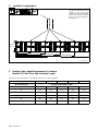
2. Insulation Configurations
1 Cut Line
Insulation is configured to be cut in
multiples of 24 in. (610 mm)
lengths. There are double stitched
lines at 24 in. Intervals. To prevent
fraying, cut to desired length be-
tween the lines.
Ref. 274 541-A
1
120.50 in. (3061 mm)
96.00 (2438 mm)
72.00 in. (1829 mm)
48.00 in. (1219 mm)
24 in. (610 mm)
16.50 in.
(419 mm)
3. Heating Cable Length Requirements For Various
Number Of Cable Turns And Insulation Length
Table lists the approximate length of cable required to wind various cable configurations.
Insulation Length In Feet 2 4 6 8 10
No. Of Cable Turns Required Cable Length In Feet
1 3.3 7.3 11.3 15.3 19.3
2 5.8 13.8 21.8 29.8 37.8
3 8.7 20.7 32.7 44.7 56.7
4 12.1 28.1 44.1 60.1 76.1
5 16.0 36.0 56.0 76.0 96.0
6 23.4 47.4 71.4 95.4 119.4

OM-274 540 Page 3
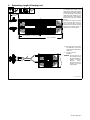
4. Determining Length of Starting Lead
1 Starting Lead
To determine the length of the
starting lead, subtract the required
cable length (from table in Section
3), from the length of the heating
cable being used, divide by 2, and
subtract 6 inches to account for the
hose bunching up while winding
the coil.
Example: A four foot long coil with
six turns requires 47.4 feet of ca-
ble. If a 50 foot cable is used to
wind this coil, the formula would be
(50−47.4)/2−.5=.8 feet (9.6 in.) of
cable lead off of the insulation.
Ref. 274 541-A
1
9.6 in.
(244 mm)
48 in. (1219mm)
24 in. (610mm)
. For the purpose of locating
the cable leads, cables are
measured from cable end to
cable end.
2 Excess Leads Off
Insulation
NOTICE − Excess leads off of
the insulation should
be routed together to
prevent secondary
magnetic fields,
which reduce energy
transfer to the part
being heated.
2
-
 1
1
-
 2
2
-
 3
3


Miller MG000000 Le manuel du propriétaire
- Taper
- Le manuel du propriétaire
dans d''autres langues
- English: Miller MG000000 Owner's manual
Documents connexes
-
Miller PROHEAT INSULATION Le manuel du propriétaire
-
-
-
Miller NA510589C Le manuel du propriétaire
-
Miller MD091017U Le manuel du propriétaire
-
Miller Electric INVISION 354MP (230/460 460/575 VOLT) Manuel utilisateur
-
Miller MH330476C Le manuel du propriétaire
-
Miller LJ310428A Le manuel du propriétaire