
Installation Manual
LP Gas Conversion Kit
NGM5056UC, NGM5656UC, NGM8056UC, NGM8656UC,
NGMP056UC, NGMP656UC, NGM8046UC, NGM8646UC

2
Table of Contents
Use and care manual
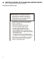
Safety Definitions .......................................................... 2
IMPORTANT SAFETY INSTRUCTIONS ........................ 3
Gas Appliance Safety .......................................................... 3
State of California Proposition 65 Warning: .................... 4
Before You Begin .......................................................... 5
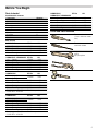
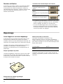
Parts Included ....................................................................... 5
Tools and Parts Needed ..................................................... 5
Installation Procedure ................................................... 6
Checklist ............................................................................... 6
Step 1 - Convert the pressure regulator .......................... 6
Step 2 - Replace the orifices ............................................. 7
Step 3 - Replace the burners, burner caps
and grates ............................................................................. 9
Step 4 - Convert valves for LP gas ................................ 11
Check Installation ....................................................... 12
Test for gas leaks ............................................................. 12
Check manifold gas pressure ........................................ 12
Final check ......................................................................... 12
Service ......................................................................... 13
Before Calling Service ..................................................... 13
Safety Definitions
Safety Defi nitions
9 WARNING
This indicates that death or serious injuries may
occur as a result of non-observance of this warning.
9 CAUTION
This indicates that minor or moderate injuries may
occur as a result of non-observance of this warning.
NOTICE: This indicates that damage to the appliance or
property may occur as a result of non-compliance with
this advisory.
Note: This alerts you to important information and/or
tips.
4XHVWLRQV"
ZZZERVFKKRPHFRPXV
:HORRNIRUZDUGWRKHDULQJIURP\RX
7KLV%RVFK$SSOLDQFHLVPDGHE\
%6++RPH$SSOLDQFHV&RUSRUDWLRQ
0DLQ6WUHHW6XLWH
,UYLQH&$

3
9 IMPORTANT SAFETY INSTRUCTIONS
READ AND SAVE THESE INSTRUCTIONS
IMPORTANT SAFET Y I NS T RUCT I ONSRE AD AND SAVE THESE INSTRUCTIONS
Gas Appliance Safety
²
'RQRWVWRUHRUXVHJDVROLQHRURWKHUIODPPDEOH
YDSRUVDQGOLTXLGVLQWKHYLFLQLW\RIWKLVRUDQ\
RWKHUDSSOLDQFH
²
:+$772'2,)<2860(//*$6
'RQRWWU\WROLJKWDQ\DSSOLDQFH
'RQRWWRXFKDQ\HOHFWULFDOVZLWFK
'RQRWXVHDQ\SKRQHLQ\RXUEXLOGLQJ
,PPHGLDWHO\FDOO\RXUJDVVXSSOLHUIURPD
QHLJKERU·VSKRQH)ROORZWKHJDVVXSSOLHU·V
LQVWUXFWLRQV
,I\RXFDQQRWUHDFK\RXUJDVVXSSOLHUFDOO
WKHILUHGHSDUWPHQW
²
,QVWDOODWLRQDQGVHUYLFHPXVWEHSHUIRUPHG
E\DTXDOLILHGLQVWDOOHUVHUYLFHDJHQF\RUWKH
JDVVXSSOLHU
:$51,1*,IWKHLQIRUPDWLRQLQWKHVHLQVWUXFWLRQV
LVQRWIROORZHGH[DFWO\DILUHRUH[SORVLRQPD\
UHVXOWFDXVLQJSURSHUW\GDPDJHSHUVRQDOLQMXU\
RUGHDWK

9 IMPORTANT SAFETY INSTRUCTIONS
READ AND SAVE THESE INSTRUCTIONS
4
BOSCH COOKTOP CONVERSION KIT FOR
TRADITIONAL MODELS NATURAL GAS (NG) TO
PROPANE (LP) GAS.
This kit is used to convert only NGMXXX6UC sealed
burner cooktops from natural gas operation to propane
gas operation. This kit cannot be used to convert other
Bosch model sealed burner cooktops, ranges, or any
other brand of cooktops.
WARNING
This conversion kit shall be installed by a qualified
service agency in accordance with the manufacturer’s
instructions and all applicable codes and requirements
of the authority having jurisdiction. If the information in
these instructions is not followed exactly, a fire, explosion
or production of carbon monoxide may result causing
property damage, personal injury or loss of life.
The qualified service agency is responsible for the
proper installation of this kit. The installation is not proper
and complete until the operation of the converted
appliance is checked as specified in the manufacturer’s
instructions supplied with the kit.
IMPORTANT: Only a qualified service technician or
installer should make this conversion.
INSTALLER: Please leave these Conversion Instructions
with this unit for the owner.
OWNER: Please retain these instructions for future
reference.
For Massachusetts Installations:
1.
Installation must be performed by a qualified or
licensed contractor, plumber, or gas fitter qualified or
licensed by the state, province or region.
2.
Shut-off valve must be a “T” handle gas cock.
3.
Flexible gas connector must not be longer than
36 inches.
CAUTION
When connecting the unit to the propane gas, make
certain the propane gas tank is equipped with its own
high pressure regulator. In addition, a pressure regulator
was supplied with the cooktop. This second regulator
must be installed with the cooktop. The maximum gas
pressure to this appliance is not to exceed 14.0 inches
water column from the propane gas tank regulator.
The following must be met when testing supply piping
system:
a) The appliance and its individual shut-off valve must be
disconnected from the gas supply piping system at test
pressures in excess of 1/2 psig (3.5 kPa).
b) The appliance must be isolated from the gas supply
piping system by closing its individual manual shut-off
valve during any pressure testing of the gas supply
piping system at test pressures equal to or less than 1/
2 psig (3.5 kPa).
State of California Proposition 65
Warning:
WARNING
This product can expose you to chemicals including vinyl
chloride, which is known to the State of California to
cause cancer and birth defects or other reproductive
harm. For more information go to
www.P65Warnings.ca.gov.
Note: IMPORTANT SAFETY NOTICE: The California Safe
Drinking and Toxic Enforcement Act requires the
Governor of California to publish a list of substances
known to the state to cause cancer, birth defect or other
reproductive harm, and requires businesses to warn
customers of potential exposure to such substances. The
burning of gas cooking fuel and the elimination of soil
during self-cleaning can generate small amounts of
carbon monoxide. The fiberglass insulation in Self Clean
ovens gives off very small amounts of formaldehyde
during the first several cleaning cycles. California lists
formaldehyde as a potential cause of cancer. Carbon
monoxide is a potential cause of reproductive toxicity.
Exposure to these substances can be minimized by:
1.
Providing good ventilation when cooking with gas.
2.
Operating the unit according to the instructions in this
manual.

5
Before You Begin
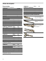
Parts Included
Installation kit contents
Main orifices
Tools and Parts Needed
Component Quantity
Conversion Kit Instructions 1
Conversion sticker 1
Foam tape 1
112 orifice 1
106 orifice 1
88 orifice 3
65 orifice 2
30 orifice 1
NGM5056UC BTU/hr kW
112 Front right 15,000 4.39
88 Front left 9,100 2.67
88 Rear left 9,100 2.67
65 Rear right 5,000 1.47
NGM8056UC, NGM8046UC BTU/hr kW
112 Center 15,000 4.39
65 Front Right 5,000 1.47
88 Front Left 9,100 2.67
65 Rear Left 5,000 1.47
88 Rear Right 9,100 2.67
NGMP056UC BTU/hr kW
106 Large Center
15,000* 4.39*
30 Small Center
65 Front Right 5,000 1.47
88 Front Left 9,100 2.67
65 Rear Left 5,000 1.47
88 Rear Right 9,100 2.67
*Combined rate of 106 and 30 orifices produce
15,000 BTU/ 4.39 kW.
NGMP656UC BTU/hr kW
106 Large Center
15,000* 4.39*
30 Small Center
88 Front Right 9,100 2.67
88 Front Left 9,100 2.67
88 Rear Left 9,100 2.67
65 Rear Right 5,000 1.47
*Combined rate of 106 and 30 orifices produce
15,000 BTU/ 4.39 kW.
NGM5656UC,
NGM8656UC, NGM8646UC
BTU/hr kW
112 Center 15,000 4.39
88 Front Right 9,100 2.67
88 Front Left 9,100 2.67
88 Rear Left 9,100 2.67
65 Rear Right 5,000 1.47
7 mm socket driver
(3 inch minimum exten-
sion)
Flat blade screwdriver,
small thin blade
Adjustable wrench
and/or
slip joint pliers
Scissors

6
Installation Procedure
Installation Procedure
This conversion process adjusts the flow of gas to the
burners to accommodate an LP gas fuel source.
9 CAUTION
TURN OFF GAS AND ELECTRICITY
Perform the following:
▯ shut off the gas valve for the gas supply line to
the cooktop
▯ remove the cooktop power cord from the
electrical outlet or turn off the breaker at the
breaker box.
▯ turn all control knobs to the “Off” position.
Checklist
Each of the following steps must be completed
correctly for the appliance to function properly.
Check off each step as it is finished.
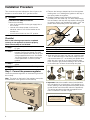
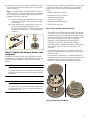
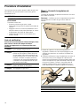
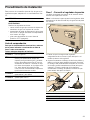
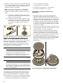
Step 1 - Convert the pressure regulator
Locate the pressure regulator on the bottom right end of
the cooktop.
Note: The arrow on the back of the regulator must point
in the direction of the gas flow to the cooktop.
1.
Remove the hexagon shaped cap from the regulator
making sure not to dislodge the gasket on the cap or
the spring inside the regulator.
2.
Grasp the plastic button stem firmly and pull it
forcefully from the metal cap. The stem snaps snugly
into an indent in the cap and may require a strong pull
to remove. (Hint: it may be helpful to gently “rock” the
plastic stem while pulling it from the metal cap.)
3.
After removing the stem from the cap, rotate the stem
180° so the button end of the stem is away from the
cap and the letters “LP” on the stem are upside down
when the cap is set flat on its head. Snap the stem
back in place in this position inserting it into the indent
in the metal cap.The stem should snap into place.
4.
Important: Attach the metallic sticker (included with
this conversion kit) to the bottom of the appliance as
shown, placing it near the appliance data plate (shows
model number and information about the appliance).
This sticker provides notice that the appliance has
been converted for use with LP gas.
Ù Step 1
Convert the pressure regulator to use
LP gas.
Ù Step 2
Remove the grates, burner caps and
burners. Remove the Natural Gas (NG)
orifices and replace them with the LP gas
orifices supplied with this kit. See Before
You Begin chapter on previous page for
correct placement of orifice by model
number.
Ù Step 3
Replace the burners, burner caps and
grates.
Ù Step 4
Adjust the unit valves to LP settings.
A Spring
B Plastic button stem
C Gasket
$
&
%
$ %
81,7&219(57(')2586(:,7+/3*$6
0$1,)2/'35(6685($7:&
$33$5(,/&219(57,328587,/,6$7,21$9(&*$=/3
35(66,21'(SR&($8',675,%87(85
81,'$'&219(57,'$'$3(752/,2/,&8)(&+2
&2/801$',675,%8,'25$'(35(6,21'($*8$$´

7
Step 2 - Replace the orifices
9 WARNING
To prevent burns, do not touch grates, burner caps
or burners while hot. Turn the cooktop off and allow
the burners to cool.
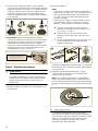
1.
Remove the grates and burner caps and burners.
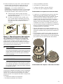
2.
Remove the orifices.
Notes
▯ The orifices require a 7 mm socket driver for
removal/replacement. The driver will need to be
inserted approximately 2^" (64 mm) into the burner
cavity to reach the orifice.
▯ To reduce the chance of the orifice being dropped
from the socket driver, add a piece of foam tape or
adhesive tape inside the socket.
Save the NG orifices in case there is need later to
restore the appliance to use natural gas again.
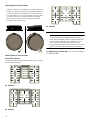
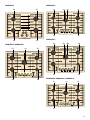
3.
Identify the correct placement of the LP gas orifices as
detailed in the Before You Begin chapter.
Note: The NGMP056UC and NGMP656UC models
have a second orifice that will be visible after the
center burner is removed. This orifice must also be
changed during the conversion to use LP gas.
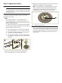
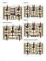
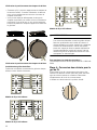
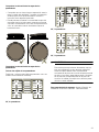
The LP gas orifice sizes corresponding to each burner
are shown in the following images. These numbers are
engraved on either the top or the side of each orifice. It
is very important to install the correct orifice size for
each burner.
A Trim a small piece of the foam tape provided
with this kit (about ]" x ^" / 6 mm x 12 mm)
B Fit this so the tape wraps against one side of
the socket so it stays in place.
C The tape will fit to the orifice and help prevent
the orifice from falling out of the socket during
extraction.
$ %
&
A Smaller center orifice
$

8
NGM5056UC
NGM8056UC, NGM8046UC
NGMP656UC
NGMP056UC
NGM5655UC, NGM8656UC, NGM8646UC

9
4.
Insert each of the LP gas orifices provided with this kit
into the socket (using the small piece of foam tape to
assure a tight fit).
Note: The NGMP056UC and NGMP656UC models
have two orifices. The larger orifice should be installed
in the center port and the smaller orifice should be
installed in the port to the side.
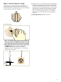
Step 3 - Replace the burners, burner caps
and grates
Replace the burners, burner caps and grates. Be sure
the grates are correctly placed and the rubber feet on the
grates engage the indents in the cooktop for proper
position.
9 WARNING
To prevent flare-ups, do not use the cooktop without
all burners, burner caps and burner grates properly
positioned.
9 WARNING
To prevent burns, do not touch burners, burner caps
or grates while hot. Turn the cooktop off and allow
the burners to cool.
The burner caps must be properly placed for the cooktop
to function properly. If the burner cap is not properly
placed, one or more of the following problems may
occur:
▯ Burner flames are too high.
▯ Flames shoot out of burners.
▯ Stainless steel discolors.
▯ Burners do not ignite.
▯ Burner flames light unevenly.
▯ Burner emits gas odor.
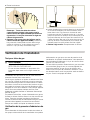
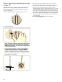
Burner Cap and Burner Base Placement
▯ The small hole or cutout near the edge of the burner
should line up with the igniter. Rotate the burner until
the igniter aligns with the electrode and gently lower it
on to the cup. The burner should not be able to rotate
when correctly placed on the cup. Pay special
attention to avoid damaging the igniter during
installation of the base. See Illustration below.
▯ Once each base is located and resting evenly, place
each burner cap on its correct burner base. See
Illustration.
▯ Place burner cap gently on top of base so that the
prongs of the burner base fit snugly into the groove of
the burner cap.
▯ If the maintop is removed by a certified installer (for
example to check electrical or piping connection) the
panhead screws that were removed must be re-
installed to ensure proper functionality of burners.
Placing Burner Caps and Bases
A Check to be sure the small piece of foam tape
used earlier is fitted to wrap against one side
of the socket.
B When pressing the socket driver onto the ori-
fice, the tape will help the orifice fit more
snugly inside the socket. This will help prevent
the orifice from falling out of the socket during
insertion.
$
%
1
2

10
Checking Burner Cap Placement
▯ Check to make sure that there is no gap between the
burner cap and burner base. See illustration below for
correct and incorrect placements of the burner cap.
▯ You may gently try to move the burner cap from side
to side to check if it is properly placed. If properly
placed, the cap will click from side to side as the
prongs hit the groove ridge.
Checking Burner Cap Placement
Install Burner Grates
Properly position and install each burner grate as shown
in the illustration below.
30” 4 Burner
30” 5 Burner
36” 5 Burner
9 WARNING
To prevent flare-ups, properly support pots and
avoid spills, all grates must be properly positioned
on the cooktop whenever the cooktop is in use.
Each of the four feet must be placed into the
corresponding dimples in the cooktop. Do not use a
grate if the rubber feet are missing or damaged.
For replacement of rubber feet: Call Customer Support
at 1-800-944-2904.

11
Step 4 - Convert valves for LP gas
The bypass jet on each valve must be adjusted. Your
cooktop may come with either hollow or solid valve
shafts. Determine the bypass screw location accordingly.
1.
Turn all knobs to the “OFF” position.
2.
Remove knobs.
Note: All cooktops have hollow stem valves except
the center valve on the NGMP units which is a solid
stem. Solid stem valves do not need to be adjusted.
3.
Hollow Stem Valves (all burners except center valve
of NGMP units): insert a long, thin flat blade
screwdriver in the hollow stem of the valve. The
adjustment screw is approximately 1 1/2" (39 mm)
from the top of the stem.
4.
Engage the tip of the screwdriver into the adjustment
screw by slowly turning the screwdriver and feeling for
the blade to engage the screw. Then turn the screw
clockwise about 70 degrees (less than 1/4 turn) until it
“bottoms out” (does not turn any further). The screw
does not take much force to turn. Once the screw
does not turn any further, stop. Do not overtighten.
Repeat for each valve until all have been adjusted
correctly.
5.
Hollow Stem Valve: Replace the knob.
êLQ
PP
2))
+,
/2

12
Check Installation
Test for gas leaks
9 WARNING
NEVER TEST FOR GAS LEAKS USING A FLAME
If any leaks are detected, do not proceed past this
step until all leaks have been eliminated.
Leak testing is to be conducted by the installer according
to the instructions given in this section.
Turn on gas. Apply a non-corrosive leak detection fluid to
all joints and fittings in the gas connection between the
shutoff valve and the cooktop. Include gas fittings and
joints in the cooktop if connections may have been
disturbed during installation. Bubbles appearing around
fittings and connections indicate a leak. An electronic
Gas Leak Detector can also be used.
If a leak appears, turn off the supply line gas shutoff
valve and tighten the leaking connections. Retest for
leaks by turning on the supply line gas shutoff valve.
When the leak check is complete (no bubbles appear),
the test is complete. Wipe off all detection fluid residue.
Check manifold gas pressure
During any pressure testing of the gas supply piping
system at test pressures greater than 14" of water
column pressure (approximately ½" psig, 3.5 kPA) it is
necessary to disconnect the cooktop and its individual
shut-off valve from the gas supply piping system.
If it should be necessary to check the manifold gas
pressure, connect a manometer (water gauge) or other
approved gas pressure reading device to the top burner
right rear orifice. Using a rubber hose with inside
diameter of approximately 1/4" hold tubing down tight
over orifice. Turn burner valve on.
Final check
After conversion is complete, place each correct sized
burner cap in its seated, notched position and check the
operation of the electric igniters. Check flame
characteristics. Flame should be blue with a minimal
yellow tip on the outer cone of the flames.
Check flame characteristics
▯ If the flame is completely or mostly yellow, verify that
the regulator is set for the correct fuel. After
adjustment, retest.
▯ Some yellow streaking is normal during the initial start-
up. Allow unit to operate 4 to 5 minutes and re-
evaluate before making adjustments.
Yellow flames:
Further adjustment is required.
Yellow tips on outer cones:
Normal for LP Gas.
Soft blue flames:
Normal for Natural Gas.

13
Service
Before Calling Service
If the igniters do not spark or the “on” indicator lights
(available in some models) do not glow, check the power
source to see if a fuse has blown or if the circuit breaker
has tripped.
Refer to the Statement of Limited Warranty in the Use
and Care Manual. See the Use and Care Manual for
troubleshooting information.
Product Rating Label
The rating label shows the model number and the FD
number (production number/product’s unique identifier)
of your cooktop. It is located on the underside of the
cooktop.
Rating Label Location
Model number and FD Number
The model number and the FD number of your appliance
are found on the rating label. Make a note of these
numbers in the space below to save time in the event
your appliance requires service.
Keep your invoice or escrow papers for warranty
validation if service is needed.
A Rating Label
Model # FD #
Bosch Customer Support 800-944-2904
$

14
Table des Matières
Notice d’uti li sati on
Définitions de sécurité ................................................ 14
IMPORTANTES CONSIGNES DE SÉCURITÉ ............. 15
Utilisation sécuritaire de l'électroménager
alimenté au gaz : ............................................................... 15
Avertissement issue de la proposition 65 de
l’État de la Californie : ...................................................... 16
Avant de commencer .................................................. 17
Pièces incluses .................................................................. 17
Outils et pièces nécessaires ........................................... 17
Procédure d'installation .............................................. 18
Liste de vérification .......................................................... 18
Étape1 : Convertir le régulateur de pression ............... 18
Étape 2 : Remplacement des ports .............................. 19
Étape 3 : Repositionnement des brûleurs,
des chapeaux de brûleur et des grilles ........................ 21
Étape 4 : Conversion des robinets pour
le gaz de PL ....................................................................... 22
Vérification de l'installation ........................................ 23
Test pour fuites de gaz .................................................... 23
Vérification de la pression d'admission du gaz .......... 23
Dernière vérification .......................................................... 24
Dépannage ................................................................... 24
Avant d'appeler le service de dépannage ................... 24
Définitions de sécurité
Défi nitions de sécurité
9 AVERTISSEMENT
Ceci indique que le non-respect de cet
avertissement peut entraîner des blessures graves,
voire la mort.
9 ATTENTION
Ceci indique que le non-respect de cet
avertissement peut entraîner des blessures légères
ou de gravité moyenne.
AVIS : Ceci indique que la non-conformité à cet avis de
sécurité peut entraîner des dégâts matériels ou
endommager l'appareil.
Remarque : Ceci vous signale des informations et/ou
indications importantes.
9RXVDYH]GHVTXHVWLRQV"
ZZZERVFKKRPHFRPXV
ââ
1RXVQRXVIHURQVXQSODLVLUGHYRXVVHUYLU
&HWDSSDUHLOpOHFWURPpQDJHU%RVFKHVWIDEULTXpSDU
%6++RPH$SSOLDQFHV&RUSRUDWLRQ
0DLQ6WUHHW6XLWH
,UYLQH&$

15
9 IMPORTANTES CONSIGNES DE SÉCURITÉ
LIRE ET CONSERVER CES INSTRUCTIONS
IMPORTANTES CONSI GNES DE SÉ CURI TÉLI RE ET CONSE R V ER CE S INSTRUCTIONS
Utilisation sécuritaire de l'électroménager alimenté au gaz :
²
1HSDVFRQVHUYHURXXWLOLVHUGHOHVVHQFHRX
GDXWUHVOLTXLGHVRXYDSHXUVLQIODPPDEOHVj
SUR[LPLWpGHFHWDSSDUHLORXGHWRXWDXWUHDSSDUHLO
²
48()$,5(6,92863(5&(9(=81(2'(85'(*$=
1HSDVHVVD\HUGHPHWWUHXQDSSDUHLOVRXVWHQVLRQ
1HSDVWRXFKHUGLQWHUUXSWHXUGHFRXUDQWpOHFWULTXH
1HSDVXWLOLVHUGHWpOpSKRQHVGDQVOpGLILFH
&RPPXQLTXHULPPpGLDWHPHQWDYHFOHIRXUQLVVHXU
GHJD]GHSXLVODSSDUHLOWpOpSKRQLTXHGXQYRLVLQ
5HVSHFWHUOHVGLUHFWLYHVGXIRXUQLVVHXUGHJD]
6LOVDYqUHLPSRVVLEOHGHMRLQGUHOHIRXUQLVVHXUGH
JD]FRPPXQLTXHUDYHFOHVSRPSLHUV
²
8WLOLVHUOHVVHUYLFHVGXQLQVWDOODWHXURXGXQHDJHQFH
GHVHUYLFHVTXDOLILpVRXOHIRXUQLVVHXUGHJD]SRXU
SURFpGHUjOLQVWDOODWLRQHWDX[UpSDUDWLRQV
$9(57,66(0(176LOHVGLUHFWLYHVQHVRQWSDV
VXLYLHVjODOHWWUHLO\DXQULVTXHGLQFHQGLHRX
GH[SORVLRQSRXYDQWHQWUDvQHUGHVGRPPDJHV
PDWpULDX[GHVEOHVVXUHVRXXQGpFqV

9 IMPORTANTES CONSIGNES DE SÉCURITÉ
LIRE ET CONSERVER CES INSTRUCTIONS
16
TROUSSE DE CONVERSION DES TABLES DE
CUISSON BOSCH, DES MODÈLES TRADITIONNELS
AU GAZ NATUREL (GN) AU GAZ PROFANE (PL).
Cette trousse est utilisée pour convertir uniquement les
brûleurs des tables de cuisson NGMXXX6UC scellés
d’un fonctionnement au gaz naturel pour être utilisé au
gaz propane. Elle ne sert pas à convertir d'autres
modèles Bosch de tables de cuisson, de cuisinières, ou
d’autres marques de tables de cuisson qui utilisent des
brûleurs scellés.
AVERTISSEMENT
Cette trousse de conversion doit être installée par une
agence de réparation qualifiée en conformité aux
directives du fabricant et de tous les autres codes et
exigences en vigueur de l'autorité ayant juridiction. Si les
directives ne sont pas suivies à la lettre, il y a un risque
d'incendie, explosion ou de génération de monoxyde de
carbone pouvant entraîner des dommages matériaux,
des blessures ou une perte de vie.
L'agence de réparation qualifiée est responsable de la
bonne installation de cette trousse. L'installation n'est
pas jugée terminée jusqu'à ce que l'on ait testé l'appareil
converti comme précisé dans les directives du fabricant
fournies avec la trousse.
IMPORTANT : Seul un technicien ou un installateur
qualifié en réparation peut procéder à cette conversion.
INSTALLATEUR : Prière de laisser les directives de
conversion avec cet appareil à l'intention du propriétaire.
PROPRIÉTAIRE : Prière de conserver ces instructions
pour référence ultérieure.
Pour les installations au Massachusetts :
1.
L'installation doit être exécutée par un entrepreneur,
un plombier ou un ajusteur d'appareils à gaz qualifié
ou autorisé par l'État, la province ou la région.
2.
Le robinet d'arrêt doit être robinet à gaz avec
poignées en T.
3.
Le connecteur à gaz souple ne doit pas dépasser
36 pouces.
ATTENTION
Lors du raccordement de l'appareil au gaz propane,
assurez-vous que le réservoir de gaz est doté de son
propre régulateur de pression élevée. De plus, un
régulateur de pression a été livré avec la table de
cuisson. Ce deuxième régulateur doit être installé avec la
table de cuisson. La pression maximale de gaz de cet
appareil ne doit pas dépasser 14 po de colonne d’eau
Au régulateur du réservoir de gaz propane.
Veuillez respecter les exigences ci-dessous lors de la
mise à l'essai de la canalisation du système
d'alimentation en gaz :
a) L'appareil et son propre robinet d'arrêt doivent être
déconnectés de la canalisation du système
d'alimentation en gaz aux pressions de test qui
dépassent 1/2 PSIG (3,5 kPa).
b) L'appareil doit être isolé de la canalisation du système
d'alimentation en gaz en fermant son propre robinet
d'arrêt manuel pour tout test à des pressions égales ou
inférieur à 1/2 PSIG (3,5 kPa).
Avertissement issue de la proposition 65
de l’État de la Californie :
AVERTISSEMENT
Ce produit peut vous exposer à des produits chimiques,
comme du chlorure de vinyle, reconnus par l’État de la
Californie comme causant le cancer, des malformations
congénitales ou d’autres effets nocifs sur la
reproduction. Pour de plus amples renseignements,
consultez www.P65Warnings.ca.gov.
Remarque : AVIS DE SÉCURITÉ IMPORTANT : En
application de la loi californienne concernant la salubrité
de l’eau et la protection contre les substances chimiques
(« California Safe Drinking Water and Toxic Enforcement
Act »), le gouverneur de Californie est tenu de publier
une liste reconnue par l’État de Californie comme étant
cancérigènes ou pouvant causer des malformations ou
présenter un danger pour la reproduction, et les
entreprises sont tenues d’avertir les consommateurs des
risques potentiels d’exposition à de telles substances. La
combustion de gaz combustible pour la cuisson et
l'élimination de résidus pendant l'autonettoyage peuvent
générer de faibles quantités de monoxyde de carbone.
Dans les fours équipés du Nettoyage Auto, de faibles
quantités de formaldéhyde peuvent se dégager lors de
l'élimination des salissures pendant les quelques
premiers cycles autonettoyants. La Californie classe le
formaldéhyde parmi les produits potentiellement
cancérigènes. Le monoxyde de carbone est une cause
possible de toxicité pour la reproduction. Il est possible
de réduire l'exposition à ces substances en :
1.
assurant une bonne ventilation lors de la cuisson au
gaz; et
2.
utilisant l'appareil selon les instructions de ce manuel.

17
Avant de commencer
Pièces incluses
Contenu de la trousse d'installation
Principaux ports
Outils et pièces nécessaires
Composant Quantité
Directives de la trousse de conversion 1
Autocollant de conversion 1
Ruban de mousse 1
Port de 112 1
Port de 106 1
Port de 88 3
Port de 65 2
Port de 30 1
NGM5056UC BTU/h kW
112 Avant droit 15 000 4,39
88 Avant gauche 9 100 2,67
88 Arrière gauche 9 100 2,67
65 Arrière droit 5 000 1,47
NGM8056UC, NGM8046UC BTU/h kW
112 Central 15 000 4,39
65 Avant droit 5 000 1,47
88 Avant gauche 9 100 2,67
65 Arrière gauche 5 000 1,47
88 Arrière droit 9 100 2,67
NGMP056UC BTU/h kW
106 Central, grand
15 000* 4,39*
30 Central, petit
65 Avant droit 5 000 1,47
88 Avant gauche 9 100 2,67
65 Arrière gauche 5 000 1,47
88 Arrière droit 9 100 2,67
*Ensemble, les ports 106 et 30 produisent
15 000 BTU/ 4,39 kW.
NGMP656UC BTU/h kW
106 Central, grand
15 000* 4,39*
30 Central, petit
88 Avant droit 9 100 2,67
88 Avant gauche 9 100 2,67
88 Arrière gauche 9 100 2,67
65 Arrière droit 5 000 1,47
*Ensemble, les ports 106 et 30 produisent
15 000 BTU/ 4,39 kW.
NGM5656UC,
NGM8656UC, NGM8646UC
BTU/h kW
112 Central 15 000 4,39
88 Avant droit 9 100 2,67
88 Avant gauche 9 100 2,67
88 Arrière gauche 9 100 2,67
65 Arrière droit 5 000 1,47
Clé pour douille de
7 mm (extension mini-
mum de 3 po)
Petit tournevis plat,
lame mince
Clé réglable
et/ou
pince multiprise
Ciseaux

18
Procédure d'installation
Procédure d’installati on
Ce processus de conversion ajuste le débit de gaz vers
les brûleurs pour accommoder la source de gaz de
combustion au PL.
9 ATTENTION
COUPER LE GAZ ET L'ALIMENTAITON
ÉLECTRIQUE
Procédez comme suit :
▯ fermez le robinet de gaz pour couper
l'alimentation en gaz de la conduite de la table de
cuisson.
▯ dégagez la fiche du cordon d'alimentation de la
table de cuisson de la prise électrique ou ouvrez
le disjoncteur du boîtier de disjoncteurs.
▯ mettez tous les boutons de commande à la
position d'arrêt.
Liste de vérification
Pour le bon fonctionnement de l'électroménager, il faut
bien achever chacune des étapes suivantes.
Cocher les étapes au fur et à mesure qu'elles sont
achevées.
Étape1 : Convertir le régulateur de
pression
Localisez le régulateur de pression au bas du coin droit
de la table de cuisson.
Remarque : La flèche au dos du régulateur doit pointer
dans la direction du débit de gaz vers la table de
cuisson.
1.
Retirez le capuchon de forme hexagonale du
régulateur. Assurez-vous de ne pas déloger le joint
extérieur du capuchon ou le ressort à l'intérieur du
régulateur.
2.
Saisissez solidement la tige de plastique du bouton et
tirez avec force pour le dégager du capuchon de
métal. La tige s'enclenche et est bien serrée dans une
rainure du capuchon et peut demander beaucoup de
force pour la retirer. (Conseil : il peut être utile de
balancer délicatement la tige de plastique tout en
tirant dessus pour le retirer du capuchon de métal.)
Ù Étape 1
Conversion du régulateur de pression
pour utilisation de gaz de PL.
Ù Étape 2
Retrait des grilles, des chapeaux de
brûleur et des brûleurs. Retirer les ports
de gaz naturel (GN) et les remplacer par
les ports de gaz de PL fournis dans cette
trousse. Consulter le chapitre Avant de
commencer de la page précédente pour
connaître le bon positionnement du port
par numéro de modèle.
Ù Étape 3
Remise en place des brûleurs, des cha-
peaux de brûleur et des grilles.
Ù Étape 4
Ajustement des robinets de l'appareil pour
les réglages au gaz de PL.
A Ressort
B Tige de plastique du bouton
C Joint extérieur
$
&
%

19
3.
Après le dégagement de la tige du capuchon, tournez
la tige sur 180 degrés de sorte que l'extrémité du
bouton de la tige est à l'écart du capuchon et les
lettres LP de la tige sont à l'envers lorsque le
capuchon est à plat sur sa tête. Enclenchez la tige en
place dans cette position en l'insérant dans la rainure
du capuchon de métal. La tige devrait s'enclencher en
place.
4.
Important : Collez l'autocollant métallique (inclus dans
cette trousse de conversion) au bas de
l'électroménager, comme illustré, pour qu'il soit près
de la plaque signalétique de l'appareil (indique le
numéro de modèle et les renseignements concernant
l'électroménager). Cet autocollant indique que
l'électroménager a été converti à une utilisation de gaz
de PL.
Étape 2 : Remplacement des ports
9 AVERTISSEMENT
Pour éviter les brûlures, ne pas toucher aux grilles,
aux chapeaux de brûleur ni aux brûleurs quand ils
sont chauds. Éteindre la table de cuisson et laisser
les brûleurs refroidir.
1.
Retirer les grilles, les chapeaux de brûleur et les
brûleurs.
2.
Retirer les ports.
Remarques
▯ Pour retirer ou remplacer les ports, vous aurez
besoin d'une clé à douille de 7 mm. La clé doit être
insérée d'au moins 2
^po (64 mm) dans la cavité
du brûleur pour atteindre le port.
▯ Pour réduire la possibilité de perdre un port au
retrait, ajouter un morceau de ruban adhésif ou de
ruban de mousse au fond de la douille.
Conserver les ports de gaz naturel au cas où il serait
nécessaire de reconvertir l'électroménager au gaz
naturel.
3.
Déterminer le bon positionnement des ports de gaz de
PL selon les consignes du chapitre Avant de
commencer.
Remarque : Les modèles NGMP056UC et
NGMP656UC comportent un deuxième port qui
deviendra visible au retrait du brûleur central. Celui-ci
doit également être remplacé au cours de la
conversion au gaz de PL.
Les diamètres des ports de gaz de PL correspondent
à chaque brûleur illustré dans les images qui suivent.
Ces chiffres sont gravés sur le dessus ou le côté de
chaque port. Il est très important d'installer le bon
diamètre de port pour chacun des brûleurs.
$ %
81,7&219(57(')2586(:,7+/3*$6
0$1,)2/'35(6685($7:&
$33$5(,/&219(57,328587,/,6$7,21$9(&*$=/3
35(66,21'(SR&($8',675,%87(85
81,'$'&219(57,'$'$3(752/,2/,&8)(&+2
&2/801$',675,%8,'25$'(35(6,21'($*8$$´
A Couper un petit morceau du ruban de mousse
(fourni) de cette trousse (environ ] x ^ po /
6 x12 mm)
B Insérer le ruban de sorte qu'il s'enroule sur une
paroi de la douille pour qu'il reste en position.
C Le ruban collera au port et l'empêchera de
tomber hors de la douille au cours de l'extrac-
tion.
A Petit port central
$ %
&
$

20
NGM5056UC
NGM8056UC, NGM8046UC
NGMP656UC
NGMP056UC
NGM5655UC, NGM8656UC, NGM8646UC
La page est en cours de chargement...
La page est en cours de chargement...
La page est en cours de chargement...
La page est en cours de chargement...
La page est en cours de chargement...
La page est en cours de chargement...
La page est en cours de chargement...
La page est en cours de chargement...
La page est en cours de chargement...
La page est en cours de chargement...
La page est en cours de chargement...
La page est en cours de chargement...
La page est en cours de chargement...
La page est en cours de chargement...
La page est en cours de chargement...
La page est en cours de chargement...
La page est en cours de chargement...
La page est en cours de chargement...
La page est en cours de chargement...
La page est en cours de chargement...
-
 1
1
-
 2
2
-
 3
3
-
 4
4
-
 5
5
-
 6
6
-
 7
7
-
 8
8
-
 9
9
-
 10
10
-
 11
11
-
 12
12
-
 13
13
-
 14
14
-
 15
15
-
 16
16
-
 17
17
-
 18
18
-
 19
19
-
 20
20
-
 21
21
-
 22
22
-
 23
23
-
 24
24
-
 25
25
-
 26
26
-
 27
27
-
 28
28
-
 29
29
-
 30
30
-
 31
31
-
 32
32
-
 33
33
-
 34
34
-
 35
35
-
 36
36
-
 37
37
-
 38
38
-
 39
39
-
 40
40


Bosch NGM8646UC Guide d'installation
- Catégorie
- Cuisinières
- Taper
- Guide d'installation
dans d''autres langues
- English: Bosch NGM8646UC Installation guide
- español: Bosch NGM8646UC Guía de instalación