
Dual Fuel Range
Installation Guide
SPECIFICATIONS, INSTALLATION,
AND MORE

2 | Wolf Customer Care 800.222.7820
Dual Fuel Range
Contents
3 Dual Fuel Range
4 Safety Precautions
5 Specifications
8 Installation
11 Troubleshooting
Features and specifications are subject to change at any
time without notice. Visit wolfappliance.com/specs for the
most up-to-date information.
Important Note
To ensure this product is installed and operated as safely
and eciently as possible, take note of the following types
of highlighted information throughout this guide:
IMPORTANT NOTE highlights information that is especially
important.
CAUTION indicates a situation where minor injury or prod-
uct damage may occur if instructions are not followed.
WARNING states a hazard that may cause serious injury or
death if precautions are not followed.
IMPORTANT NOTE: Throughout this guide, dimensions in
parentheses are millimeters unless otherwise specified.
IMPORTANT NOTE: Save these instructions for the local
electrical inspector.

wolfappliance.com | 3
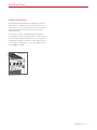
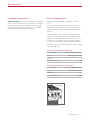
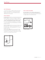
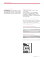
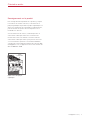
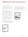
Product Information
Important product information, including the model and
serial number, are listed on the product rating plate. The
rating plate is located on the bottom of the control panel,
at the far right, just above the oven door. Refer to the
illustration below.
If service is necessary, contact Wolf Factory Certified
Service with the model and serial number. For the name of
the nearest Wolf Factory Certified Service or for questions
regarding the installation, visit the Product Support section
of our website, wolfappliance.com, or call Wolf Customer
Care at 800-222-7820.
RATING PLATE
Rating plate location
Dual Fuel Range

4 | Wolf Customer Care 800.222.7820
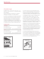
ANTI-TIP
DEVICE
1
1
/
2
"
(38)
–1
7
/
8
"
(48)
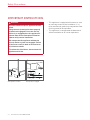
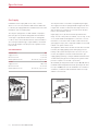
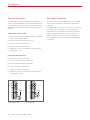
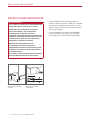
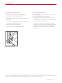
Anti-tip device location
Anti-tip device engaged
• This appliance is equipped with casters on two
or more legs and must be installed on ⁄"
(3)
thick commercial grade vinyl composition floor
finishing materials or equivalent.
• This appliance is not approved for downward
airflow ventilation or air curtain equivalent.
Safety Precautions
IMPORTANT INSTRUCTIONS
WARNING
A child or adult can tip this appliance and be
killed.
Verify the anti-tip device has been properly
installed and engaged. Ensure the anti-tip
device is re-engaged when this appliance is
moved. Refer to the illustrations below for
how to verify correct installation.
Do not operate this appliance without the
anti-tip device in place and engaged. Failure
to do so can result in death or serious burns
to children or adults.
To reduce the risk of burns, do not move this
appliance while hot.

wolfappliance.com | 5
Electrical Requirements
Installation must comply with all applicable electrical
codes.
Locate the electrical supply flush with the wall or floor
and within the shaded area shown in the illustration on
page 7. A separate circuit servicing only this appliance is
required.
If a power supply cord is used, the cord must be desig-
nated for use with ranges and rated for 240 V, 30 or 50
amps (refer to the chart below), and must include 3 or 4
conductors. A 4-conductor cord is required for installa-
tions where grounding through the neutral is prohibited.
Performance may be compromised if the electrical supply
is less than 240 volts.
ELECTRICAL REQUIREMENTS—SINGLE OVEN
Electrical Supply grounded, 240/208 VAC, 60 Hz
Service 30 amp dedicated circuit
Total Amps 21
Max Connected Load 5.2 kW
ELECTRICAL REQUIREMENTS—DOUBLE OVEN
Electrical Supply grounded, 240/208 VAC, 60 Hz
Service 50 amp dedicated circuit
Total Amps 42.5
Max Connected Load 10.2 kW
Installation Requirements
IMPORTANT NOTE: When installing against a combustible
surface, a minimum 10"
(254) riser is required for a 36" dual
fuel range with charbroiler or griddle and all 48" and 60"
models. Follow all minimum clearances to combustible
surfaces shown in the illustration on page 7.
Specifications
RATING PLATE
Rating plate location

6 | Wolf Customer Care 800.222.7820
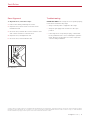
The range must be connected to a regulated gas supply.
The supply line must be equipped with an approved exter-
nal gas shut-o valve located near the range in an acces-
sible location. Do not block access to the shut-o valve.
Refer to the illustration below.
A gas supply of ⁄"
(19) ID line must be provided to the
range. If local codes permit, a certified, 3'
(.9 m) long, ⁄" (13)
or ⁄"
(19) ID flexible metal appliance connector is recom-
mended to connect the units ⁄" NPT female inlet to the
gas supply line. Pipe joint compounds suitable for use with
natural or LP gas should be used.
The appliance and its shut-o valve must be disconnected
from the gas supply piping system during any pressure
testing of the system at test pressures in excess of .5 psi
(3.5 kPa). The appliance must be isolated from the gas
supply piping system by closing its individual manual shut-
o valve during any pressure testing of the system at test
pressures equal to or less than .5 psi
(3.5 kPa).
Wolf natural gas ranges will function up to 10,250'
(3124 m)
in altitude without adjustment and LP gas ranges will func-
tion up to 8,600'
(2621 m). If the installation exceeds these
elevations, contact an authorized Wolf dealer for a high
altitude conversion kit.
Gas Supply
Installation must comply with local codes, or in the
absence of local codes, with the National Fuel Gas Code.
Locate the gas supply within the shaded area shown in the
illustration on the following page.
The range is equipped for use with natural or liquid pro-
pane (LP) gas. The product rating plate has information
on the type of gas that should be used. For rating plate
location, refer to the illustration below. If this information
does not agree with the type of gas available, check with
the local gas supplier. The gas pressure regulator is built
into the unit.
GAS REQUIREMENTS
NATURAL GAS WC
Supply Pressure 5" (12.5 mb)
Min Line Pressure 7" (17.5 mb)
Max Regulator Pressure 14" (34.9 mb), .5 psi (3.5 kPa)
LP GAS WC
Supply Pressure 10" (25 mb)
Min Line Pressure 11" (27.4 mb)
Max Regulator Pressure 14" (34.9 mb), .5 psi (3.5 kPa)
SHUT-OFF VALVE
OPEN POSITION
GAS SUPPLYTO APPLIANCE
Gas shut-o valve
Specifications
RATING PLATE
Rating plate location

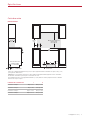
wolfappliance.com | 7
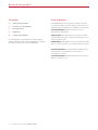
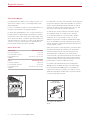
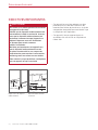
E
A
4
7
/8"
(124)
8
1
/2"
(216)
G
ELECTRICAL
AND GAS IN
‘A’ LOCATION
ONLY
FRONT VIEWSIDE VIEW
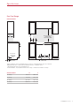
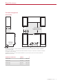
*Without ventilation hood, 36" (914) minimum clearance countertop to combustible materials, 44" (1118) for charbroiler.
NOTE: Shaded area above countertop indicates minimum clearance to combustible surfaces,
combustible materials cannot be located within this area.
For island installation, 12"
(305) minimum clearance back of range to combustible rear wall above countertop.
13"
(330)
18"
(457)
6"
(152)
W
OPENING WIDTH
30" (762) TO 36" (914)
TO BOTTOM OF
VENTILATION HOOD*
2"
(51)
OPENING WIDTH W A
30" Range 30" (762) 10⁄" (260)
36" Range 36" (914) 16⁄" (413)
48" Range 48" (1219) 18⁄" (464)
60" Range 60" (1524) 18⁄" (464)
Specifications
Dual Fuel Range
INSTALLATION

8 | Wolf Customer Care 800.222.7820
Preparation
Before moving the range, protect any finished flooring and
secure the oven door(s) closed to prevent damage.
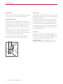
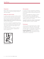
OVEN DOOR REMOVAL
To lighten the load or to fit through a doorway, the oven
door(s) can be removed. Remove only if necessary. Do not
remove the griddle or any other component. Door removal
should be done only by a certified installer or service
technician. Do not lift or carry the oven door by the door
handle.
To remove, open the door completely. Rotate both hinge
locks forward to the open position, remove the screw
closest to the hinge on both sides of the door, and pull the
door forward. Refer to the illustration below.
To reinstall, slide the door onto the hinges. Rotate the
hinge locks back completely and install the screws.
Placement
The range has rear casters which allow for easy movement
by lifting the front of the unit. Do not lift or carry the range
by the oven door handle.
Use an appliance dolly to move the range near the open-
ing. Place the appliance dolly on the side or back to pre-
vent damage. Remove and recycle packing materials. Do
not discard the anti-tip bracket supplied with the range.
If a riser has been specified, refer to the installation instruc-
tions packaged with the riser. The riser must be installed
before the range is installed.
Leveling
Raise the range to its desired height by adjusting the front
legs and rear casters. Use a ⁄" socket to adjust the rear
casters. The front legs can be adjusted by rotating the leg
clockwise to raise and counterclockwise to lower.
IMPORTANT NOTE: For 48" and 60" models, equally
distribute the load to all three front legs and rear casters.
HINGE
LOCK
SCREW
Oven door removal
Installation

wolfappliance.com | 9
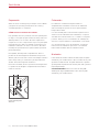
Anti-Tip Bracket
To prevent the range from tipping forward, the anti-tip
bracket must be installed. To ensure the anti-tip bolt
engages the bracket, refer to the illustration below to
determine proper placement.
INSTALL BRACKET
Drywall application: After properly positioning the anti-tip
bracket, mark the holes, then use a Phillips screwdriver
or a low rpm power drill to drive the wall anchor into the
surface of the wallboard until flush. Pre-drill the holes if
needed. For hard wallboard or double-board construc-
tion, use a ⁄" drill bit. For solid plaster, use a ⁄" drill bit.
Use the provided #8 screws and flat washers to fasten the
bracket to the wall.
Wood floor application: After properly positioning the anti-
tip bracket, drill ⁄"
(5) pilot holes through the floor. Use
the provided #12 screws and flat washers to secure the
bracket to the floor.
Concrete floor application: After properly positioning
the anti-tip bracket, drill ⁄"
(10) holes into the concrete
a minimum of 1⁄"
(38) deep. Use the provided ⁄" wedge
anchors to secure the bracket to the floor.
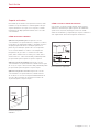
ANTI-TIP BOLT ADJUSTMENT
Once the bracket is secure, adjust the anti-tip bolt so the
top of the washer is 1⁄" (38) to 1⁄" (48) from the floor.
Slide the range into the opening and verify the anti-tip bolt
is engaged. Refer to the illustration below.
ANTI-TIP
BRACKET
6
1
/4"
(159)
Anti-tip bracket location
1
1
/
2
"
(38)
–1
7
/
8
"
(48)
Anti-tip bolt engaged
Installation

10 | Wolf Customer Care 800.222.7820
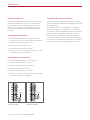
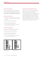
Electrical Connection
The terminal block on the back of the range allows for a
3-wire or 4-wire installation. Remove the terminal block
cover to expose the screws with corresponding numbers.
Route the wires through the strain relief and to the termi-
nal block.
THREE-WIRE INSTALLATION
1 Move the metal ground strap to positions one and two.
Refer to the illustration below.
2 Connect green/ground to position one.
3 Connect red/L2 to position three.
4 Connect black/L1 to position four.
5 Tighten the screws on the strain relief and install the
terminal block cover.
FOUR-WIRE INSTALLATION
1 Remove the metal ground strap.
2 Connect green/ground to position one.
3 Connect white/neutral to position two.
4 Connect red/L2 to position three.
5 Connect black/L1 to position four.
6 Tighten the screws on the strain relief and install the
terminal block cover.
REMOVE
6
5
4
3
2
1
INSTALL
6
5
4
3
2
1
Three- and four-wire
Three-wire only
Installation
Gas Supply Connection
All connections to the gas piping must be wrench-tight-
ened. Do not overtighten or allow pipes to turn when
tightening.
If a flexible metal connector is used, verify it is not kinked,
then attach the gas supply line to the gas inlet on the
range. Open the valve and check for leaks by placing a
liquid detergent solution onto all gas connections.
Bubbles around the connections indicate a gas leak.
If a leak appears, close the shut-o valve and adjust the
connections.

wolfappliance.com | 11
Troubleshooting
IMPORTANT NOTE: If the range does not operate properly,
follow these troubleshooting steps:
• Verify electrical power is supplied to the range.
• Verify the gas supply shut-o valve is in the open
position.
• If the range does not operate properly, contact Wolf
Factory Certified Service. Do not attempt to repair the
range. Wolf is not responsible for service required to
correct a faulty installation.
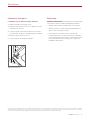
Door Alignment
To adjust the door, follow these steps:
1 Remove the skirt by extracting the screws.
2 Open the door, and loosen the nut. Refer to the
illustration below.
3 Close the door, and turn the screw clockwise to raise
and counterclockwise to lower the door.
4 Open the door, and tighten the nut.
5 Close the door, and reinstall the skirt.
NUT
SKIRT
ADJUSTMENT
SCREW
Door alignment
Sub-Zero, Sub-Zero & Design, Sub-Zero & Snowflake Design, Dual Refrigeration, The Living Kitchen, Great American Kitchens The Fine Art of Kitchen Design, Wolf, Wolf &
Design, Wolf Gourmet, W & Design, red colored knobs, Cove, and Cove & Design are registered trademarks and service marks of Sub-Zero Group, Inc. and its subsidiaries.
All other trademarks are property of their respective owners in the United States and other countries.
Installation

2 | Atención al cliente de Wolf 800.222.7820
Estufa de energía dual
Contenido
3 Estufa de energía dual
4 Precauciones de seguridad
5 Especificaciones
8 Instalación
11 Solución de problemas
Las características y especificaciones están sujetas a
cambios sin previo aviso. Visite wolfappliance.com/specs
para obtener la información más actualizada.
Aviso importante
Para garantizar que este producto se instale y opere de
la forma más segura y eficiente posible, tome nota de los
siguientes tipos de información resaltada en este manual:
AVISO IMPORTANTE señala la información que es
especialmente importante.
PRECAUCIÓN indica una situación en la que se pueden
sufrir heridas leves o provocar daños al producto si no se
siguen las instrucciones.
ADVERTENCIA indica peligro de que se produzcan heridas
graves o incluso la muerte si no se siguen las precauciones.
AVISO IMPORTANTE: En toda esta guía, las dimensiones
entre paréntesis son milímetros, a menos que se
especifique lo contrario.
AVISO IMPORTANTE: Guarde estas instrucciones para el
inspector eléctrico local.

wolfappliance.com | 3
Información del producto
La información importante del producto, incluidos el
modelo y el número de serie de la unidad, se encuentra
en la placa de datos del producto. La placa de datos se
encuentra en la parte inferior del panel de control, en el
extremo derecho, justo por encima de la puerta del horno.
Consulte la siguiente ilustración.
Si es necesario realizar algún servicio, póngase en contacto
con el servicio certificado de fábrica de Wolf y tenga a
mano el modelo y el número de serie. Para obtener los
datos del centro de Servicio certificado de fábrica de Wolf
más cercano o si tiene preguntas acerca de la instalación,
visite la sección de soporte del producto en nuestra página
de Internet wolfappliance.com; o bien, llame a la línea de
atención al cliente de Wolf al 800-222-7820.
PLACA DE DATOS
Ubicación de la placa de datos
Estufa de energía dual

4 | Atención al cliente de Wolf 800.222.7820
INSTRUCCIONES IMPORTANTES
ADVERTENCIA
Si un niño o un adulto jalan el electrodoméstico
este puede volcarse y causarles la muerte.
Compruebe que el dispositivo antivuelco
haya sido instalado y esté enganchado
correctamente. Asegúrese de volver a
enganchar el dispositivo antivuelco después de
cambiar el electrodoméstico de lugar. Consulte
las ilustraciones siguientes para saber cómo
comprobar su instalación correcta.
No opere este electrodoméstico sin
el dispositivo antivuelco en posición y
enganchado. No seguir esta instrucción puede
resultar en la muerte o en graves quemaduras
en niños o adultos.
Para reducir el riesgo de quemaduras, no mueva
el electrodoméstico mientras está caliente.
DISPOSITIVO
ANTIVUELCO
1
1
/
2
"
(38)
–1
7
/
8
"
(48)
Ubicación del dispositivo
antivuelco
Dispositivo antivuelco
enganchado
• Este electrodoméstico está equipado con
ruedas en dos o más patas y debe ser instalado
sobre pisos de grado comercial con ⁄"
(3) de
grosor, hechos de materiales compuestos con
vinilo o equivalentes.
• Este electrodoméstico no ha sido aprobado
para la ventilación con flujo de aire dirigido
hacia abajo o una cortina de aire equivalente.
Precauciones de seguridad

wolfappliance.com | 5
Requisitos eléctricos
La instalación debe cumplir con todos los códigos
eléctricos vigentes.
Coloque el suministro eléctrico a ras con la pared o
el piso y dentro del área sombreada que se muestra
en la ilustración de la página 7. Se necesita un circuito
independiente que le suministre electricidad únicamente a
este electrodoméstico.
Si se utiliza un cable de alimentación, el cable debe haber
concebido para uso con estufas y tener capacidad para
240 V, 30 o 50 amperes (consulte la tabla siguiente), y
debe incluir 3 o 4 conductores. Se requiere un cable de 4
conductores para instalaciones en las que está prohibido
realizar la conexión a tierra a través del cable neutro.
El rendimiento puede verse comprometido si el suministro
eléctrico es menor a 240 voltios.
REQUISITOS ELÉCTRICOS—HORNO SENCILLO
Suministro eléctrico Con conexión a tierra, 240/208 V CA, 60 Hz
Servicio Circuito dedicado de 30 amperes
Total de amperes 21
Carga máxima conectada 5.2 kW
REQUISITOS ELÉCTRICOS—HORNO DOBLE
Suministro eléctrico Con conexión a tierra, 240/208 V CA, 60 Hz
Servicio Circuito dedicado de 50 amperes
Total de amperes 42,5
Carga máxima conectada 10.2 kW
Requisitos de instalación
AVISO IMPORTANTE: al realizar la instalación contra una
superficie combustible, se requiere una tarima con altura
mínima de 10"
(254) para una estufa de energía dual de 36"
con parrilla o plancha y para todos los modelos de 48" y
60". Mantenga todos los espacios mínimos a las superficies
combustibles, como se muestra en la ilustración de la
página 7.
Especificaciones
PLACA DE DATOS
Ubicación de la placa de datos

6 | Atención al cliente de Wolf 800.222.7820
La estufa debe conectarse a un suministro de gas regulado.
La línea del suministro debe estar equipada con una llave
de paso externa aprobada para gas ubicada cerca de la
estufa en un lugar accesible. No bloquee el acceso a la
llave de paso. Consulte la siguiente ilustración.
Se debe proporcionar una línea de suministro de gas
⁄"
(19) para la estufa. Si el código local lo permite,
se recomienda utilizar un conector metálico flexible
certificado, de 3'
(.9 m) de largo, ⁄" (13) o ⁄" (19) de
diámetro interior para conectar la entrada NPT hembra
de ⁄" de la unidad a la línea de suministro de gas. Debe
utilizar compuestos para juntas de tubería aptos para uso
con gas natural o gas LP.
Debe desconectar el electrodoméstico y la llave de paso
del sistema de tuberías del suministro de gas durante
cualquier prueba de presión del sistema a presiones
de prueba mayores a 0.5psi
(3.5kPa). Debe aislar el
electrodoméstico del sistema de tuberías del suministro
de gas cerrando manualmente la llave de paso durante
cualquier prueba de presión del sistema a presiones de
prueba iguales o inferiores a 0.5psi
(3.5kPa).
Las estufas a gas natural de Wolf funcionarán hasta
10,250'
(3124 m) de altitud sin ajuste y las estufas a gas
LP funcionarán hasta 8,600'
(2621 m). Si la instalación
supera estas elevaciones, póngase en contacto con un
distribuidor autorizado de Wolf para conseguir un kit de
conversión para regiones altas.
Suministro de gas
La instalación debe cumplir con los códigos locales, o en
ausencia de códigos locales, con el Código Nacional de
Gas Combustible.
Localice el suministro de gas en la zona sombreada que se
muestra en las ilustración de la página siguiente.
La estufa está equipada para su uso con gas licuado (LP) o
propano natural. La placa de datos del producto contiene
información sobre el tipo de gas que se debe utilizar. Para
ubicar la placa de datos, consulte la siguiente ilustración. Si
esta información no coincide con el tipo de gas disponible,
consulte con el proveedor de gas local. El regulador de
presión de gas está incorporado a la unidad.
REQUISITOS DEL GAS
GAS NATURAL COLUMNA DE AGUA
Presión de suministro 5" (12.5 mb)
Presión mínima de la línea 7" (17.5 mb)
Presión máxima del
regulador
14" (34.9 mb), .5 psi (3.5 kPa)
GAS LP COLUMNA DE AGUA
Presión de suministro 10" (25 mb)
Presión mínima de la línea 11" (27.4 mb)
Presión máxima del
regulador
14" (34.9 mb), .5 psi (3.5 kPa)
LLAVE DE PASO
EN POSICIÓN ABIERTA
SUMINISTRO
DE GAS
A LA UNIDAD
Llave de paso del suministro
de gas
Especificaciones
PLACA DE DATOS
Ubicación de la placa de datos

wolfappliance.com | 7
E
A
4
7
/
8
"
(124)
8
1
/2"
(216)
G
ELÉCTRICA Y
DE GAS EN LA
UBICACIÓN ‘A’
SOLAMENTE
VISTA FRONTALVISTA LATERAL
13"
(330)
18"
(457)
6"
(152)
W
ANCHO DE LA ABERTURA
30" (762) A 36" (914)
A LA PARTE INFERIOR DE LA
CAMPANA DE VENTILACIÓN
*
2"
(51)
*Sin campana de ventilación, se requiere una distancia mínima de 36" (914) desde el mostrador hasta los materiales combustibles,
y 44"
(1118) para la parrilla.
NOTA: La zona sombreada sobre el mostrador indica la distancia mínima a las superficies combustibles, los materiales combustibles
no se pueden colocar en esta área.
Para instalaciones en islas, se necesita una distancia mínima de 12” (305) en la parte posterior de la estufa a la pared trasera
inflamable sobre el mostrador.
ANCHO DE LA ABERTURA ANCHO A
Estufa de 30" 30" (762) 10⁄" (260)
Estufa de 36" 36" (914) 16⁄" (413)
Estufa de 48" 48" (1219) 18⁄" (464)
Estufa de 60" 60" (1524) 18⁄" (464)
Especificaciones
Estufa de energía dual
INSTALACIÓN

8 | Atención al cliente de Wolf 800.222.7820
Preparación
Antes de mover la estufa, proteja cualquier suelo acabado
y asegúrese de que la(s) puerta(s) del horno esté(n) y
cerrada(s) para que no se dañe(n).
CÓMO QUITAR LA PUERTA DEL HORNO
La(s) puerta(s) del horno puede(n) removerse para aligerar
la carga o conseguir que pase a través de una puerta. Solo
deberá quitarse si es necesario. No retire la plancha ni
ninguno de los otros componentes. El proceso para quitar
la puerta del horno debe ser realizado solamente por un
instalador certificado o un técnico de servicio. No utilice
la manija de la puerta del horno para levantar la puerta ni
para transportarla.
Para quitarla, abra la puerta completamente. Gire los
pestillos de las dos bisagras hacia adelante a la posición
abierta, quite el tornillo más cercano a la bisagra en ambos
lados de la puerta, y a continuación jale la puerta hacia
delante. Consulte la siguiente ilustración.
Para volver a instalar, deslice la puerta en las bisagras. Gire
los pestillos de las bisagras completamente hacia atrás e
instale los tornillos.
Colocación
La estufa tiene ruedas traseras para facilitar su
desplazamiento levantando el frente de la unidad. No
utilice la manija de la puerto de horno para levantar o
transportar la estufa.
Use una carretilla para electrodomésticos para mover la
estufa cerca de la abertura. Para evitar daños, coloque la
carretilla del electrodoméstico en el costado o en la parte
posterior. Retire y recicle los materiales de embalaje. No
deseche el soporte antivuelco suministrado con la estufa.
Si se ha especificado el uso de una tarima, consulte las
instrucciones de instalación que vienen con la tarima.
Debe instalar la tarima antes de instalar la estufa.
Nivelación
Para levantar la estufa a la altura deseada, ajuste las patas
delanteras y las ruedas traseras. Utilice una llave de ⁄" para
ajustar las ruedas traseras. Las patas delanteras se pueden
ajustar girando la pata hacia la derecha para subir y hacia la
izquierda para bajar.
AVISO IMPORTANTE: Para los modelos de 48" y 60",
distribuya la carga equitativamente sobre las tres patas
delanteras y las ruedas traseras.
TORNILLO
BLOQUEO
DE BISAGRA
Cómo quitar la puerta
del horno
Instalación

wolfappliance.com | 9
Soporte antivuelco
Para evitar que la estufa se vuelque hacia el frente, debe
instalarse el soporte antivuelco. Para asegurarse de que
el perno antivuelco se acople con el soporte, consulte
la ilustración de abajo para determinar cómo colocarlo
correctamente.
CÓMO INSTALAR EL SOPORTE
Aplicación en panel de yeso: Después de colocar
correctamente el soporte antivuelco, marque los orificios,
luego utilice un desarmador Philips o un taladro eléctrico
a bajas rpm para introducir el anclaje de pared en el
panel de yeso hasta que quede a ras con la superficie.
Si es necesario taladre los orificios con anticipación.
Para paneles de yeso duro o construcción de doble
placa, utilice una broca de ⁄". Para yeso sólido, utilice
una broca de ⁄". Utilice tornillos #8 y arandelas planas
proporcionados para sujetar el soporte a la pared.
Aplicación en piso de madera: Después de colocar
correctamente el soporte antivuelco, taladre orificios guía
de ⁄"
(5) en el piso. Utilice tornillos #12 y arandelas planas
proporcionados para asegurar el soporte al piso.
Aplicación en piso de concreto: Después de colocar
correctamente el soporte antivuelco, taladre orificios
de ⁄"
(10) en el concreto a una profundidad mínima de
1⁄"
(38). Utilice anclajes de cuña proporcionados de
⁄" para asegurar el soporte al piso.
CÓMO AJUSTAR EL PERNO ANTIVUELCO
Una vez que el soporte está asegurado, ajuste el perno
antivuelco de manera que parte superior de la arandela
quede a 1⁄"
(38) a 1⁄" (48) del piso. Deslice la estufa
dentro de la abertura y compruebe que el perno antivuelco
esté enganchado. Consulte la siguiente ilustración.
SOPORTE
ANTIVUELCO
6
1
/4"
(159)
Ubicación del soporte
antivuelco
1
1
/
2
"
(38)
–1
7
/
8
"
(48)
Perno antivuelco enganchado
Instalación

10 | Atención al cliente de Wolf 800.222.7820
Conexión eléctrica
El bloque de terminales en la parte posterior de la estufa
permite una instalación de 3 cables o 4 cables. Retire
la cubierta del bloque de terminales para exponer los
tornillos con los números correspondientes. Guíe los
cables a través del liberador de tensión y al bloque de
terminales.
INSTALACIÓN DE TRES CABLES
1 Mueva la banda metálica de conexión a tierra a las
posiciones uno y dos. Consulte la siguiente ilustración.
2 Conecte verde/tierra a la posición uno.
3 Conecte rojo/L2 a la posición tres.
4 Conecte negro/L1 a la posición cuatro.
5 Apriete los tornillos en el liberador de tensión e instale
la cubierta del bloque de terminales.
INSTALACIÓN DE CUATRO CABLES
1 Quite la banda metálica de conexión a tierra.
2 Conecte verde/tierra a la posición uno.
3 Conecte blanco/neutral a la posición dos.
4 Conecte rojo/L2 a la posición tres.
5 Conecte negro/L1 a la posición cuatro.
6 Apriete los tornillos en el liberador de tensión e instale
la cubierta del bloque de terminales.
RETIRE
6
5
4
3
2
1
INSTALE
6
5
4
3
2
1
Tres y cuatro cables
Tres cables solamente
Instalación
Conexión del suministro de gas
Todas las conexiones a la tubería de gas deben apretarse
con llave. No apriete demasiado ni permita que las tuberías
giren al apretarlas.
Si se utiliza un conector de metal flexible, compruebe
que no esté doblado y, a continuación, conecte la línea
de suministro de gas a la entrada de gas de la estufa. Abra
la válvula y revise si hay fugas mediante la colocación
de una solución de detergente líquido sobre todas las
conexiones de gas. La presencia de burbujas alrededor de
las conexiones es indicador de una fuga de gas. Si aparece
una fuga, cierre la llave de paso y ajuste las conexiones.
La page est en cours de chargement...
La page est en cours de chargement...
La page est en cours de chargement...
La page est en cours de chargement...
La page est en cours de chargement...
La page est en cours de chargement...
La page est en cours de chargement...
La page est en cours de chargement...
La page est en cours de chargement...
La page est en cours de chargement...
La page est en cours de chargement...
La page est en cours de chargement...
-
 1
1
-
 2
2
-
 3
3
-
 4
4
-
 5
5
-
 6
6
-
 7
7
-
 8
8
-
 9
9
-
 10
10
-
 11
11
-
 12
12
-
 13
13
-
 14
14
-
 15
15
-
 16
16
-
 17
17
-
 18
18
-
 19
19
-
 20
20
-
 21
21
-
 22
22
-
 23
23
-
 24
24
-
 25
25
-
 26
26
-
 27
27
-
 28
28
-
 29
29
-
 30
30
-
 31
31
-
 32
32


dans d''autres langues
- English: Wolf DF30450SPLP Installation guide
- español: Wolf DF30450SPLP Guía de instalación