
INSTALLATION INSTRUCTIONS FOR
GX SERIES LEVER LOCK: 3U15 & 3U65 FUNCTIONS
A7590A 1
INSTALLATION INSTRUCTIONS FOR LEVER LOCK ON DOORS FROM 1-3/8” (35MM) TO 1-3/4” (45MM) THICK:
For installation assistance, contact SARGENT at 800-727-5477
INSTRUCTIVO DE INSTALACION CERRADURA TUBULAR
DE MANIJA PARA ESPESORES DE PUERTA DE:
min: 1-3/8" (35mm) max: 1-3/4" (45mm)
INSTRUCTIONS POUR L´INSTALLATION SERRURE TUBULAIRE A
POIGNEE POUR EPAISSEURS DE PORTE DE:
min: 1-3/8" (35mm) max: 1-3/4" (45mm)
TOOLS REQUIRED FOR THE LOCK INSTALLATION
Circular hole saws 2-1/8" (54mm) and 1" (25mm) in diameter. 1" (25mm) and 1/8" (3mm) drill bits,
Philips screwdriver, hammer, chisel, drill and lever removing tool.
OUTILS EMPLOYES POUR L´INSTALLATION DE LA SERRURE.
Découpeuse circulaire, scie circulaire ou tarière à main de 2-1/8" (54mm), y 1" (25mm).
-Tarière de 1" (25mm) ou de 1/8" (3mm). -Marteau, foret, tournevis Philips, pointeau ou pointe,
bédane.
HERRAMIENTAS UTILIZADAS PARA LA INSTALACION DE SU CERRADURA.
Cortacirculo, sierra circular ó broca de mano de 2-1/8" (54mm) y de 1" (25mm). Broca de
1/8" (3mm) o de 1" (25mm). Martillo, taladro, desarmador Phillips, punzón ó ·"punta", formón.
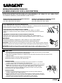
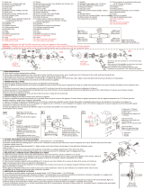
IMPORTANT:
The latchbolt assembly is designed for 2-3/8" (60mm) or 2-3/4" (70mm) backset.
To change the backset, move the square hub forward or backward as shown.
IMPORTANT: Le pêne de cette serrure a été déssiné pour fonctionner à 2-3/8" (60mm) ou 2-3/4" (70mm) de
l´épaisseur de la porte. Pour changer la mesure du pêne, faites glisser la pièce mobile indiquée sur la figure.
IMPORTANTE: El pestillo de está cerradura ha sido diseñado para funcionar a 2-3/8" (60mm) ó 2-3/4" (70mm)
del canto de la puerta. Para cambiar la medida del pestillo, deslice la pieza móvil indicada en la figura.
MARQUEZ LA PORTE
a) Marquez une ligne horizontale sur le battant de la porte à la hauteur ou vous dèsirez
installer la serrure. Nous recommendons 38" (965mm) du sol.
b) Placez le modéle ci-joint en la forme indiquée par la figure et marquez le centre du cercle.
NOTE: Avant de marquer le centre du cercle, choisissez la distance à laquelle vous dèsirez
faire le trou, toujours selon la longueur du pêne: 2-3/8" (60mm) ou 2-3/4" (70mm).
c) Marquez la partie centrale de I´épaisseur de la porte pour faire le trou pour le pêne.
d) Faites deux trous 1/8" (3mm) de diamètre.
MARQUE LA PUERTA
a) Marque una línea horizontal en la hoja de la puerta a la altura que desee instalar la
cerradura, sugerimos a 38" (965mm) del piso.
b) Coloque la plantilla anexa en la forma que indica la figura y marque el centro del círculo.
NOTA: antes de marcar el centro del círculo, elija la distancia a que desee hacer el agujero,
dependiendo de la longitud del pestillo: 2-3/8" (60mm) ó 2-3/4" (70mm).
c) Marque la parte central del canto de la puerta para el agujero del pestillo.
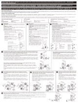
MARK DOOR
a) Mark a horizontal line on the face of the door at the height that the lock is to be installed.
38" (965mm) from finished floor is recommended.
b) Place cutout template as shown on outside of door and mark the center of the lock cutout at the
desired backset.
c) Mark the center of the door edge for the latch hole.
d) Mark the location of the two 1/8" (3mm) holes.
1

A7590A2
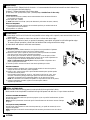
INSTALL OUTSIDE LEVER
Insert outside lever mounting posts (a) and spindle (b) through holes in latch.
Make certain that the spindle is inserted through the square hub with the ‘U’ up or down as shown.
INSTALL LATCH
a) Insert latch until front is flush with and parallel to door edge; with a pencil, trace around latch front and
remove latch.
b) With chisel, cut pocket for latch front so that it is flush with door edge.
When using the drive-in latch, no pocket is necessary. Insert latch and press in until solid against edge.
To ensure proper operation, check that the latchbolt flat is aligned with door edge.
c) Insert latch and secure it with two wood screws.
BORE HOLES
a) Bore the 2-1/8" (54mm) hole for the lock. It is recommended that hole be bored from both sides of the
door to prevent surface chipping.
b) Bore 1" (25mm) latchbolt hole in door edge.
c) Drill two, 1/8" (3mm) holes, 1/16" (1.6mm) deep. Outside face of door only.
HAGA LOS AGUJEROS
a) Para cerradura de 2-1/8" (54mm). Se recomienda perforar por ambos lados de la
puerta para evitar que se astille.
b) Para pestillo: 1" (25mm).
FAITES LES TROUS
a) Pour Serrure: de 2-1/8" (54mm). Nous recommendons forer des deux côtés de la
porte éviter les échardes.
b) Pour pêne de 1" (25mm).
c) NOTE: (Faites deux trous 1/8" (3mm) de diametre à profondeur de 1/16" (1.6mm).
INSTALLEZ LE PENE
a) Installez le pêne en faisant attention à ce que le front soit parallèle è I`èpaisseur
de la porte. Marquez le contour du front et rétirez le pêne.
b) Faites la "boite" pour la partie en face (le front) avec la profondeur necèssaire
pour que le front soit au ras de I`èpaisseur de laporte.
Pour le pêne, pour I`encastrer "drive-in" (sans front), on ne fait pas la "bôite".
Pour le placer, introduisez et poussez jusqu`à ce qu´il soit au ras de I´épaisseur de
la porte, toujours en vérifiant I´alignement de la tète du.
NOTE: si I´alignement de la tète du pêne n´est pas paralléle à I´épaisseur de la
porte, le pêne pourra échouer.
c) Insèrez le pêne à nouveau et fixez-le avec des vis spèciales pour bois.
INSTALE EL PESTILLO
a) Inserte el pestillo cuidando que el frente quede paralelo al canto de la puerta,
marque el contorno del frente y retire el pestillo.
b) Haga la "caja" para el frente con la profundidad necesaria para que éste quede
a ras del canto de la puerta.
Para el pestillo para empotrar "drive in" (sin frente) no se hace la "caja". Para
colocarlo, introduzca y empuje hasta que quede a ras del canto de la puerta
verificando la alineación de la cabeza del pestillo con el canto de la puerta.
NOTA: Si la alineación de la cabeza del pestillo no es paralela al canto de la puerta,
c) Inserte nuevamente el pestillo y fijelo con tornillos para madera.
el pestillo puede fallar.
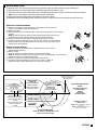
PLACEZ LA POIGNEE EXTERIEURE
Introduisez la poignée extérieure qui a deux piquets. (a) et un profil d´entraînement, (b) dans
les trous du pêne.
NOTE: Vérifiez le placement correcte du profil d´entraînement et de la barre comme I´indique
la figure.
COLOQUE LA MANIJA EXTERIOR
Introduzca la manija exterior la cual tiene dos postes (a) y un parfil de arrastre (b) en los
agujeros del pestillo.
NOTA: Verifique la colocación correcta del perfil de arrastre y de la barra como lo indica la
figura.
2
3
4

A7590A 3
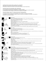
INSTALL INSIDE LEVER
a) Remove lever from mounting plate tube by pressing catch on side of lever body and sliding off.
b) Separate rose from mounting plate by separating at notched edge of rose.
c) Place lever tube and mounting plate over inside spindle and screw in place with screws and lock washers.
Note: Do not over tighten mounting screws as lock could bind.
d) Place rose over mounting plate and press until it clicks in place.
e) Assemble lever by depressing catch and sliding lever on tube until catch protrudes through lever slot.
INSTALLEZ LA POIGNEE INTERIEURE
a) Rétirez la poignée de I´unité intérieure, en appuyant sur la cale avec une
"pointe" en la faisant glisser vers I´extérieur.
b) Rétirez la rosette.
c) Vissez en employant les machine à laber a de la serrure de la dent et les vis les plus
longues.
NOTE: Quand vous serez en train de visser, vérifiez que la serrure fonctionne
correctement. Si les vis sont trop serrées, la serrure pourra échouer.
d) Placez la rosette sur la plaquette de montage jusqu´à réussir un click.
e) Placez la poignée en appuyant sur la cale avec une "pointe" et faites glisser la
poignée jusquá ce que la cale puisse se voir de I´autre coté, c´est a dire, qu´elle
passe au de-la de la poignée.
INSTALE LA MANIJA INTERIOR
a) Retire la manija de la unidad interior, oprimiendo la con una "punta" y
deslizándola hacia afuera.
b) Retire la roseta.
c) Atornille usando las rondanas estrella y los tornillos más largos.
NOTA: Al atornillar verifique que la cerradura funcione correctamente, si los tornillos se
aprietan en exceso la cerradura puede fallar.
d) Coloque la roseta en la placa de montaje hasta lograr el click.
e) Coloque la manija oprimiendo la cuña con una "punta" y deslice la
manija hasta que la cuña sobresalga por la ranura de la manija.
Mark for a 1" (25mm) hole.
Marquez le centre de l´epaisseur
de la porte pour fire un trou de
1" (25mm).
Marque el centro del canto de la
puerta para un agujero de
1" (25mm).
DOBLE AQUI SOBRE EL
CANTO DE LA PUERTA
FOLD HERE
ON THE EDGE OF THE DOOR
PLIEZ ICI, SUR L´EPAISSEUR DE LA PORTE
CORTE A LO LARGO DE LA LINEA
CUT ALONG THESE LINES
2-3/8" (60mm)
2-3/4" (70mm)
CENTER POINT
CENTRE DU FORET
CENTRO DEL BARRENO
COUPEZ EN SUIVANT LA LONGUEUR DE LA LIGNE
TEMPLATE TO INSTALL
TUBULAR SET
MODELE POUR INSTALLER
SERRURE TUBULAIRE
PLANTILLA PARA INSTALAR
CERRADURA TUBULAR
NOTE: Use template on
outside of door
NOTE: Placez le modéle sur l´exterieur
de la porte
NOTA: Coloque la plantilla por el
exterior de la puerta
ANTES DE
RECORTAR LEA
LAS INSTRUCCIONES
READ INSTRUCTIONS BEFORE
CUTTING
AVANT DE DECOUPER, LISEZ
LES INSTRUCTIONS
2-1/8" (54 mm) HOLE
TROU FORAGE DE 2-1/8" (54 mm)
PERFORACION DE 2-1/8" (54 mm)
(2) 1/8" (3mm) HOLES ON
OUTSIDE FACE OF DOOR ONLY
SELECT ACCORDING TO
DESIRED BACKSET
1-3/4"
(45mm)
1-3/8"
(35mm)
5

A7590A4
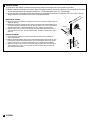
INSTALL STRIKE
a) Close door and mark a horizontal line from the center of the latch bolt to the frame of the door.
b) Measure half the thickness of the door. Mark this distance with a vertical line starting from the butt of the frame
and at the intersection of the two lines drill a 1" (25mm) diameter hole, 1/2" (13mm) deep.
c) Center the holes of the strike with the vertical line and trace the outline of the strike. Cut out a 1/16" (1.6mm)
deep pocket for the strike, mount with two screws provided.
INSTALLEZ LA CONTRE
a) Fermez la porte et marquez une ligne horizontale du centre du modèle jusqu´au
cadre de la porte.
b) Mésurez la moitié de l´épaisseur de la porte. Marquez cette même distance avec
une ligne verticale a partir du butoir du cadre et faites un trou sur l´intersection
des deux lignes de 1" (25mm) de diamétre et 1/2" (13mm) de profondeur.
c) Aligner les trous de la contre avec la ligne verticale. Marquez le contour de la
contre et faites la “boîte” avec un fond de 1/16" (1.6mm) Fixez la contre avec
deux vis.
INSTALE LA CONTRA.
a) Cierre la puerta y marque una línea horizontal del centro de la plantilla al
marco de la puerta.
b) Mida la mitad del espesor de la puerta, ésta misma distancia márquela con una
línea vertical a partir del tope del marco y en la intersección de las dos líneas
haga un orificio de 1" (25mm) de diámetro y 1/2" (13mm) de profundidad.
c) Alinear los orificios de la contra con la línea vertical, marque el contorno de la
contra y elabore su "caja" con un fondo de 1/16" (1.6mm). Fije la contra con
dos tornillos para madera.
6
Frame
Door
-
 1
1
-
 2
2
-
 3
3
-
 4
4


Autres documents
-
Kimex 032-1014 Guide d'installation
-
 Arctek Y3S3CZ-238 Mode d'emploi
-
 Sure-Loc Hardware IN301-CDR 32D Guide d'installation
-
Defiant 721-181-H Manuel utilisateur
-
Defiant T8610 Mode d'emploi
-
-
 Arctek L3S5C Mode d'emploi
-
-
Global Door Controls GAL-1180L-626-M Mode d'emploi
-


