Hitachi NT 32AE2 (S) Instruction And Safety Manual
- Catégorie
- Cloueuse
- Taper
- Instruction And Safety Manual
Ce manuel convient également à

Instruction and safety manual
Manuel d’instructions et de sécurité
Instrucciones y manual de seguridad
Model
Brad Nailer
Modèle
Cloueur pour Brads
Modelo
Clavadora para Brads
NT 50AE2 (S) • NT 32AE2 (S)
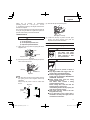
DANGER
Improper use of this Nailer can result in death or serious injury!
This Manual contains important information about product safety.
Read and understand this Manual before operating the Nailer.
Never allow anyone who has not reviewed this manual to use the tool.
This manual should be stored in safe place.
DANGER
Une utilisation incorrecte et sans respecter la sécurité de ce cloueur risque d’entraîner la mort
ou des blessures graves !
Ce manuel renferme des instructions importantes sur la sécurité de l’outil.
Lire et bien assimiler ce manuel avant d’utiliser le cloueur.
Cet outil ne doit jamais être utilisé par une personne n’ayant pas pris connaissance du manuel.
Ce mode d’emploi doit être conservé dans un endroit sûr.
PELIGRO
¡La utilización inadecuada e insegura de este clavador puede resultar en lesiones serias o en la
muerte!
Este manual contiene información importante sobre la seguridad del producto.
Lea y entienda este manual antes de utilizar el martillo neumático.
La herramienta no deberá utilizarse sin haber leído previamente este manual.
Este manual debe ser guardado en un lugar seguro.

2
CONTENTS
Page
IMPORTANT SAFETY INFORMATION ........................3
DEFINITIONS OF SIGNAL WORDS ............................3
EXPLANATION OF THE NAILING ACTION
OF THE HITACHI NAILER ....................................3
SAFETY
IMPORTANT SAFETY INSTRUCTIONS -
FOR USING NAILERS .............................................4
EMPLOYER’S RESPONSIBILITIES .............................7
OPERATION
NAME OF PARTS ........................................................8
SPECIFICATIONS ........................................................9
NAIL SELECTION ........................................................9
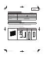
ACCESSORIES .........................................................10
STANDARD ACCESSORIES .................................10
OPTIONAL ACCESSORIES ..................................10
APPLICATIONS .........................................................10
BEFORE OPERATION ...............................................10
Page
WORKING ENVIRONMENT ..................................10
AIR SUPPLY ..........................................................10
LUBRICATION ......................................................11
COLD WEATHER CARE .......................................11
TESTING THE NAILER .........................................11
ADJUSTING AIR PRESSURE ...............................12
LOADING NAILS ..................................................13
NAILER OPERATION ................................................13
METHODS OF OPERATION ..................................14
ADJUSTING THE NAILING DEPTH .......................15
CHANGING THE EXHAUST DIRECTION ..............16
USING THE NOSE CAP ........................................16
MAINTENANCE
MAINTENANCE AND INSPECTION ..........................17
SERVICE AND REPAIRS ...........................................18
PARTS LIST ................................................................58
English
ÍNDICE
Español
Página
INFORMACIÓN IMPORTANTE SOBRE
SEGURIDAD ......................................................39
DEFINICIÓN DE LAS PALABRAS CLAVE ..................39
EXPLICACIÓN LA ACCIÓN DE CLAVADO DEL
CLAVADOR HITACHI ..........................................39
SEGURIDAD
INSTRUCCIONES IMPORTANTES DE SEGURIDAD
PARA LA UTILIZACIÓN DEL CLAVADOR ..........40
RESPONSABILIDADES DEL EMPRESARIO ............44
OPERACIÓN
NOMENCLATURA ......................................................45
ESPECIFICACIONES ................................................46
SELECCIÓN DE CLAVOS .........................................46
ACCESORIOS ...........................................................47
ACCESORIOS ESTÁNDAR ...................................47
ACCESORIOS OPCIONALES ...............................47
APLICACIONES .........................................................47
Página
ANTES DE LA OPERACIÓN ......................................47
ENTORNO DE TRABAJO .....................................47
SUMINISTRO DE AIRE .........................................47
LUBRICACIÓN ......................................................48
CUIDADOS PARA CLIMAS FRÍOS ........................48
PRUEBA DEL CLAVADOR ....................................48
AJUSTE DE LA PRESIÓN DE AIRE .......................50
CARGA DE CLAVOS .............................................50
OPERACIÓN DEL CLAVADOR ..................................51
MÉTODOS DE OPERACIÓN ................................51
AJUSTE DE LA PROFUNDIDAD DE CLAVADO ....53
CAMBIO DEL SENTIDO DEL AIRE DE ESCAPE ...54
UTILIZACIÓN DE LA TAPA PARA EL MORRO ......54
MANTENIMIENTO
MANTENIMIENTO E INSPECCIÓN ...........................55
SERVICIO Y REPARACIONES ..................................56
LISTA DE PIEZAS .......................................................58
Page
INFORMATION IMPORTANTE DE SÉCURITÉ ..........20
DEFINITION DES MOTS DE SIGNALISATION ..........20
EXPLICATION DE L’ACTION DE CLOUAGE DU
CLOUEUR HITACHI ............................................20
SECURITE
CONSIGNES DE SÉCURITÉ IMPORTANTES POUR
L’UTILISATION DU CLOUEUR ...........................21
RESPONSABILITES DE L’EMPLOYEUR ...................25
UTILISATION
NOM DES P IECES ....................................................26
SPECIFICATIONS ......................................................27
SELEC TION DES CLOUS .........................................27
ACCESSOIRES .........................................................28
ACCESSOIRES STANDARD .................................28
ACCESSOIRES EN OPTION ................................28
APPLICATIONS .........................................................28
AVANT L’UTILISATION ...............................................28
Français
Page
ENVIRONNEMENT DE TRAVAIL ..........................28
ALIMENTATION D’AIR ...........................................28
GRAISSAGE ..........................................................29
ENTRETIEN PAR TEMPS FROID ..........................29
ESSAI DU CLOUEUR ............................................29
REGLAGE DE LA PRESSION D’AIR .....................31
CHARGEMENT DES CLOUS ...............................31
UTILISATION DU CLOUEUR .....................................31
METHODES D’UTILISATION ................................32
REGLAGE DE LA PROFONDEUR DE CLOUAGE ...34
CHANGEMENT DU SENS D’ECHAPPEMENT ......35
UTILISATION DU CAPUCHON DE BEC ...............35
ENTRETIEN
ENTRETIEN ET INSPECTION ...................................36
ENTRETIEN ET REPARATIONS ...............................37
LISTE DES PIÈCES ....................................................58
TABLE DES MATIÈRES

3
English
IMPORTANT SAFETY INFORMATION
Read and understand tool labels and all of the operating instructions, safety precautions and warnings
in this manual before operating or maintaining this Nailer.
Failure to follow warnings could result in DEATH or SERIOUS INJURY
Most accidents that result from the operation and maintenance of Nailers are caused by the failure to observe basic
safety rules or precautions. An accident can often be avoided by recognizing a potentially hazardous situation before it
occurs, and by observing appropriate safety procedures.
Basic safety precautions are outlined in the “SAFETY” section of this Manual and in the sections which contain the
operation and maintenance instructions.
Hazards that must be avoided to prevent bodily injury or machine damage are identifi ed by DANGERS and WARNINGS
on the Nailer and in this Manual.
NEVER use this Nailer for applications other than those specifi ed in this Manual.
DEFINITIONS OF SIGNAL WORDS
DANGER indicates an imminently hazardous situation which, if not avoided, will result in death or serious injury.
WARNING indicates a potentially hazardous situation which, if not avoided, could result in death or serious injury.
CAUTION indicates a potentially hazardous situation which, if not avoided, may result in minor or moderate injury, or
may cause machine damage.
NOTE emphasizes essential information.
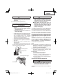
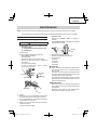
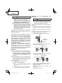
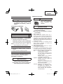
EXPLANATION OF THE NAILING ACTION OF THE HITACHI NAILER
○
SINGLE SEQUENTIAL ACTUATION MECHANISM:
First, press the push lever against the wood; next, pull the trigger to drive the fastener.
After nailing once, nailing will not be possible again until the Trigger is released and pressed again.
○
CONTACT ACTUATION MECHANISM:
First, press the push lever against the wood; next, pull the trigger to drive the fastener.
First, pull the trigger; next, press the push lever against the wood to drive the fastener.
If the Trigger is held back, a nail will be driven each time the Push Lever is pressed against the wood.

4
English
SAFETY
IMPORTANT SAFETY INSTRUCTIONS - FOR USING NAILERS
INSTRUCTIONS PERTAINING TO A RISK OF FIRE, ELECTRIC SHOCK, OR INJURY TO PERSONS
●
General
To reduce the risks of electric shock, fi re, and injury to persons, READ ALL THE INSTRUCTIONS BEFORE USING
THE TOOL.
DANGER
1. OPERATORS AND OTHERS IN WORK AREA
MUST WEAR EYE PROTECTION (SAFETY
GLASSES WITH SIDE SHIELDS).
When operating the Nailer, always wear
safety glasses with side shields, and
make sure others in work area wear
safety glasses, too.
Safety glasses must conform to the
requirements of American National
Standards Institute, ANSI Z87.1 and
provide protection against fl ying particles
both from the front and side.
The employer must enforce the use of
safety glasses by the Nailer operator and
others in work area.
2. NEVER USE OXYGEN OR OTHER BOTTLED
GASES. EXPLOSION MAY OCCUR.
Never use oxygen, combustible gases or
any other bottled gases as a power
source for the Nailer.
Use of the above gases is dangerous, as
the Nailer will explode.
Use only clean, dry, regulated
compressed air.
WARNING
3. NEVER POINT TOOL AT YOURSELF OR OTHERS
IN WORK AREA.
Always assume that the Nailer contains
fasteners.
Never point the Nailer toward yourself or
others, whether it contains fasteners or
not.
If fasteners are mistakenly driven, it can
lead to severe injuries.
Never engage in horseplay with the
Nailer.
Respect the Nailer as a working
implement.
4. DO NOT PLACE FINGER ON TRIGGER AND KEEP
FINGER AWAY FROM THE TRIGGER WHEN NOT
DRIVING FASTENERS TO AVOID ACCIDENTAL
FIRING.
Never carry the Nailer with fi nger on Trigger since
you could drive a fastener unintentionally and injure
yourself or someone else.
Always carry the Nailer by the handle only.
5. CHOICE OF TRIGGERING METHOD IS
IMPORTANT.
Read and understand section titled “METHODS OF
OPERATION.” (pages 14 – 15)
6. DO NOT MAKE CONTACT WITH SAFETY TIP
(PUSH LEVER) WHEN NOT DRIVING FASTENERS.

5
English
SAFETY — Continued
WARNING
When using tools, basic precautions should always be followed, Including the following:
1. Work area
(1) Keep the work area clean and well lighted.
Cluttered benches and dark areas increase the risks
of electric shock, fi re, and injury to persons.
(2) Do not operate the Nailer in explosive
atmospheres, such as in the presence of
fl ammable liquids, gases, or dust.
The Nailer is able to create sparks resulting in the
ignition of the dust or fumes.
(3) Keep bystanders, children, and visitors away
while operating the Nailer. Distractions are able to
result in the loss of control of the Nailer.
2. Personal safety
(1) Stay alert. Watch what you are doing and use
common sense when operating the Nailer.
Do not use the Nailer while tired or under the
infl uence of drugs, alcohol, or medication.
A moment of inattention while operating the Nailer
increases the risk of injury to persons.
(2) Dress properly. Do not wear loose clothing or
jewelry. Contain long hair. Keep hair, clothing,
and gloves away from moving parts.
Loose clothes, jewelry, or long hair increases the
risk of injury to persons as a result of being caught in
moving parts.
(3) Avoid unintentional starting. Be sure the switch
is off before connecting to the air supply. Do
not carry the Nailer with your fi nger on the switch or
connect the Nailer to the air supply with the switch on.
(4)
– Disconnect the Nailer from
the air source before making adjustments, doing
Nailer maintenance, clearing jams, touching
the Push Lever, when not in use, leaving work
area, loading, or unloading the Nailer, handing
it to another person. Never attempt to clear a jam
or repair the Nailer unless you have disconnected
air hose from the Nailer and removed all remaining
fasteners from the Nailer. The Nailer should never be
left unattended since people who are not familiar with
the Nailer might handle it and injure the themselves.
Such precautionary measures reduce the risk of
injury to persons.
(5) Do not overreach. Keep proper footing and
balance at all times. Proper footing and balance
enables better control of the Nailer in unexpected
situations.
(6) Use safety equipment. A dust mask, non-skid
safety shoes and a hard hat must be used for the
applicable conditions.
(7)
– Risk of hearing loss. Wear
ear protection.
(8) Always wear head protection.
Always wear head protection to protect your
head from fl ying objects.
(9) Do not attach the hose or Nailer to your body.
Attach the hose to the structure to reduce the risk of
loss of balance if the hose shifts.
(10)
– Place Nailer properly on
workpiece. Do not fasten on top of another fastener.
This is able to cause the fastener to be defl ected and
hit someone, or cause the Nailer to react and result in
a risk of injury to persons.
3. Nailer use and care
(1) Use clamps or another practical way to secure
and support the workpiece to a stable platform.
Holding the work by hand or against the body is
unstable and is able to lead to loss of control.
(2) Do not force the Nailer. Use the correct Nailer for
the application. The correct Nailer will do the job
better and safer at the rate for which the Nailer is
designed.
(3) Do not use the Nailer if the switch does not
turn the Nailer on or off . Any Nailer that cannot be
controlled with the switch is dangerous and must be
repaired.
Never use Nailer which is defective or operating
abnormally. If the Nailer appears to be operating
unusually, making strange noises, or otherwise
appears defective, stop using it immediately and
arrange for repairs by a Hitachi authorized service
center.
(4) Disconnect the Nailer from the air source before
making any adjustments, changing accessories,
or storing the Nailer. Such preventive safety
measures reduce the risk of starting the Nailer
unintentionally.

6
English
(5) Store the Nailer when it is idle out of reach of
children and other untrained persons. A Nailer is
dangerous in the hands of untrained users.
(6) Maintain the Nailer with care. Keep the
Nailer Clean and lubricated for better and safer
performance.
(7) Check for misalignment or binding of moving
parts, breakage of parts, and any other condition
that aff ects the Nailer’s operation.
If damaged, have the Nailer serviced before using.
Because of high air pressure in the Nailer, cracks in
the surface are dangerous. To avoid this, do not drop
the Nailer or strike the Nailer against hard surfaces;
and do not scratch or engrave signs on the Nailer.
Many accidents are caused by poorly maintained
Nailers. There is a risk of bursting if the Nailer is
damaged.
(8) Use only accessories that are identifi ed by
Hitachi for the specifi c Nailer. Use of an accessory
not intended for use with the specifi c Nailer, increases
the risk of injury to persons.
(9) Use only those fasteners listed in the
Accessories section of this manual. Fasteners not
identifi ed for use with this Nailer by Hitachi are able to
result in a risk of injury to persons or Nailer damage
when used in this Nailer.
4. Service
(1) Tool service must be performed only by qualifi ed
repair personnel.
(2) When servicing a Nailer, use only identical
replacement parts. Use only authorized parts.
(3) Use only the lubricants supplied with the Nailer
or specifi ed by Hitachi.
5. Air source
(1) Never connect to an air source that is capable of
exceeding 200 psi (13.7 bar 14 kgf/cm
2
).
Over pressurizing the Nailer is able to result in
bursting, abnormal operation, breakage of the Nailer
or serious injury to persons.
DO NOT EXCEED 120 psi (8.3 bar 8.5 kgf/cm
2
).
Use only clean, dry, regulated compressed air at the
rated pressure or within the rated pressure range as
marked on the Nailer.
Always verify prior to using the Nailer that the air
source has been adjusted to the rated air pressure or
within the rated air-pressure range.
(2) Never use oxygen, carbon dioxide, combustible
gases or any bottled gas as an air source for the
Nailer. Such gases are capable of explosion and
serious injury to persons.
6. Others
(1) Before starting work, check the nailing operation
switching device.
This Hitachi nailer includes a nailing operation
switching device.
Before starting work, check the setting of the
operation switching device.
If the switching device is not set properly, the nailer
will not operate correctly.
(2) Be careful of double fi re due to recoil. If the Push
Lever is unintentionally allowed to re-contact the
workpiece following recoil, an unwanted fastener will
be driven. In order to avoid this undesirable double
fi re,
○
Intermittent operation (Trigger fi ring)
1) Set the switching device to SINGLE SEQUENTIAL
ACTUATION MECHANISM.
2) Pull the trigger rapidly and fi rmly.
○
Continuous operation (Push lever fi ring)
1) Set the switching device to CONTACT
ACTUATION MECHANISM.
2) Do not press the nailer against the wood with
excessive force.
3) Separate the nailer from the wood as it recoils
after nailing.
(3) Never Use NON relieving coupler on Nailer. If a
non relieving coupler is used on the Nailer, the Nailer
can remain charged with air after disconnecting
and thus will be able to drive a fastener even after
disconnecting. The Nailer and air hose must have a
hose coupling such that all pressure is removed from
the Nailer when the coupling joint is disconnected.
SAFETY — Continued
WARNING

7
English
(4) Check Push Lever before use. Make sure the
Push Lever operates properly. (The Push Lever may
be called “Safety”.) Never use the Nailer unless the
Push Lever is operating properly, otherwise the Nailer
could drive a fastener unexpectedly. Do not tamper
with or remove the Push Lever, otherwise the Push
Lever becomes inoperable.
(5) Keep all screws and covers tightly in place. Keep
all screws and covers tightly mounted.
Check their condition periodically. Never use the
Nailer if parts are missing or damaged.
(6) Do not load fasteners with Trigger or Push Lever
depressed. When loading fasteners into the Nailer
or when connecting the air hose,
1) do not depress the Trigger;
2) do not depress the Push Lever; and
3) keep the Nailer pointed downward.
(7) Keep hands and feet away from fi ring head
during use. Never place your hands or feet closer
than 8 inches (200 mm) from the fi ring head. A
serious injury can result if the fasteners are defl ected
by the workpiece, or are driven away from the point of
entry.
(8) Do not drive fasteners into thin boards or near
corners and edges of workpiece.
The fasteners can be driven through or away from the
workpiece and hit someone.
(9) Never drive fasteners from both sides of a wall
at the same time. The fasteners can be driven into
and through the wall and hit a person on the opposite
side.
(10) Check for live wires. Avoid the risk of severe
electrical shock by checking for live electrical wires
that may be hidden by walls, fl oors or ceilings. Turn
off the breaker switch to ensure there are no live
wires.
(11) Never carry Nailer by hose.
(12) Do not disconnect air hose from Nailer with
fi nger on Trigger. The Nailer can fi re when re-
connected to An air supply.
(13) Handle Nailer correctly. Operate the Nailer
according to this Manual. Never allow the Nailer to
be operated by children, individuals unfamiliar with its
operation or unauthorized personnel.
(14) Never use Nailer for applications other than
those specifi ed in this manual.
(15) Never modify or alter a Nailer. Doing so may cause
it to malfunction and personal injuries may result.
SAFETY — Continued
WARNING
EMPLOYER’S RESPONSIBILITIES
1. Ensure that this MANUAL is available to operators
and personnel performing maintenance.
2. Ensure that Nailers are used only when operators and
others in work area are wearing EYE PROTECTION.
3. Enforce the use of EYE PROTECTION by operators
and others in work area.
4. Keep Nailers in safe working order.
5. Maintain Nailers properly.
6. Ensure that Nailers which require repair are not
further used before repair.
SAVE THIS MANUAL AND
KEEP IT AVAILABLE FOR OTHERS!

8
English
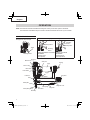
OPERATION
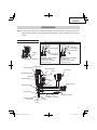
NOTE: The information contained in this Manual is designed to assist you in the safe operation of the Nailer.
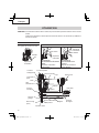
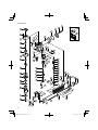
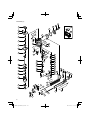
Some illustrations in this Manual may show details or attachments that diff er from those on your own Nailer.
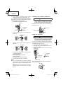
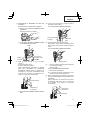
Outlet (Firing head)
Push lever
Exhaut cover
Piston o-ring
Driver blade
Lock lever
Guide plate
Piston
Nose cap
Feed spring
Trigger
Valve part
Air plug
Magazine
Body
Top cover
Magazine cover
Stop lever
Adjuster
NAME OF PARTS
Trigger
Enlarged view of the valve part
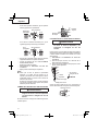
Switching device
Nailing operation switching device
Switching
Device
Upward position
Switching
Device
Downward position
SINGLE SEQUENTIAL ACTUATION
MECHANISM
(Switching device:
upward position)
CONTACT ACTUATION
MECHANISM
(Switching device:
downward position)

9
English
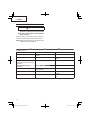
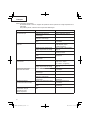
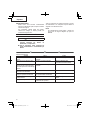
SPECIFICATIONS
Model NT50AE2 (S) NT32AE2 (S)
Operating pressure 70 – 120 psi (4.9 – 8.3 bar, 5 – 8.5 kgf/cm
2
)
Dimensions
Length × Height × Width
10" × 9-3/16" × 2-3/8"
(254 mm × 233 mm × 60 mm)
10" × 7-3/4" × 2-3/8"
(254 mm × 197 mm × 60 mm)
Weight 2.2 lbs. (1.0 kg) 2.0 lbs. (.9 kg)
Nail capacity 100 Nails
Air consumption
.025 ft
3
/cycle at 100 psi
(.73 ltr/cycle at 6.9 bar)
(.73 ltr/cycle at 7 kgf/cm
2
)
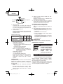
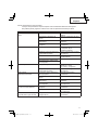
NAIL SELECTION
WARNING
●
Be sure to use only the genuine HITACHI nails for the NT50AE2 (S), NT32AE2 (S). The use of any other
nails can result in tool malfunction and/or nail breakdown, leading to serious injuries.
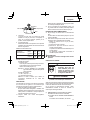
Only nails shown in the Table below can be driven with this Nailer.
Dimensions of nails
18 Gauge brad nails
Min. Max.
NT50AE2 (S) • NT32AE2 (S) NT50AE2 (S) NT32AE2 (S)
.075" (1.9 mm)
5/8" (16 mm)
.043" (1.1 mm)
.049"
(1.25 mm)
.039"
(1 mm)
2" (50 mm)
1-1/4" (32 mm)

10
English
ACCESSORIES
WARNING
●
Accessories other than those shown below
can lead to malfunction and resulting
injuries.
STANDARD ACCESSORIES
2
1
3
1
Safety glasses 1
2
Nose cap (mounted on tool) 2
3
Case 1
OPTIONAL ACCESSORIES ... sold separately
○
Pneumatic Tool Lubricant
1 oz. (30 cc) oil feeder (Code No.877153)
4 oz. (120 cc) oil feeder (Code No.874042)
1 quart (1 ltr) can (Code No.876212)
NOTE: Accessories are subject to change without any
obligation on the part of HITACHI.
APPLICATIONS
○
Cabinet and picture frame assembly, furniture trim.
○
On-site and mobile home trim and molding.
BEFORE OPERATION
Read section titled “SAFETY” (pages 4 – 7).
Make sure of the followings before operation.
WORKING ENVIRONMENT
WARNING
●
No fl ammable gas, liquid or other fl ammable
objects at worksite.
●
Clear the area of children or unauthorized
personnel.
AIR SUPPLY
DANGER
●
NEVER use oxygen or other
bottled gases. Explosion
may occur.
WARNING
●
Never connect Nailer to pressure which
potentially exceeds 200 psi (13.7 bar
14 kgf/cm
2
).
●
Never use non relieving coupler on Nailer.
1. Power source
○
Use only clean, dry, regulated compressed air as a
power source for this Nailer.
○
Air compressors used to supply compressed air to
this Nailer must comply with the requirements of
the latest version of ANSI Standard B 19.3 “Safety
Standard For Compressors For Process Industries.”
○
Moisture or oil in the air compressor may accelerate
wear and corrosion in the Nailer.
Drain daily.
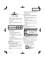
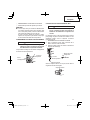
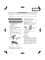
2. Filter-Regulator-Lubricator
○
Use a regulator with a pressure range of 0 – 120 psi
(0 – 8.3 bar 0 – 8.5 kgf/cm
2
).
○
Filter-regulator-lubricator units supply an optimum
condition for the Nailer and extend the Nailer life.
These units should always be used.
Filter ............ The fi lter removes moisture and dirt
mixed in compressed air.
Drain daily unless fi tted with an
automatic drain.
Keep the fi lter clean by regular
maintenance.
Regulator ..... The regulator controls the operating
pressure for safe operation of the Nailer.
Inspect the regulator before operation to
be sure it operates properly.
Lubricator .... The lubricator supplies an oil mist to the
Nailer.
Inspect the lubricator before operation
to be sure the supply of lubricant is
adequate.
Use Hitachi pneumatic tool lubricant.

11
English
Nailer side
Filter
Lubricator
Compressor side
Regulator
3. Air hose
Air hose must have a minimum working pressure
rating of 150 psi (10.4 bar 10.6 kgf/cm
2
) or 150% of
the maximum pressure produced in the system,
whichever is higher.
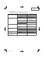
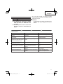
4. Air consumption
Using the Air consumption table and the Air
compressor size formula, fi nd a correct compressor
size.
Air consumption table
Operating pressure
psi
(bar)
(kgf/cm
2
)
80
(5.5)
(5.6)
90
(6.2)
(6.3)
100
(6.9)
(7)
Air consumption
ft
3
/cycle
(Itr/cycle)
.019
(.55)
.023
(.64)
.025
(.73)
Air compressor size formula
Amount of air required
= number of Nailers
× average nails driven each minute per Nailer
× air consumption at given air pressure
× safety factor (always 1.2)
Example: 3 Nailers (NT50AE2 (S) or NT32AE2 (S))
operating at 100 psi driving 30 nails per
minute
Amount of air required
= 3 × 30 × .025 (.73) × 1.2
= 2.7 CFM (ft
3
/min) (78.8 ltr/min)
After making the calculations as shown above, you
should fi nd a compressor providing 2.7 CFM of air
that is required.
LUBRICATION
It is important that the Nailer be properly lubricated.
Without proper lubrication, the Nailer will not work
properly and parts will wear prematurely.
○
Use Hitachi pneumatic tool lubricant.
Do not use detergent oil or additives. These lubricants
will harm the O-rings and other rubber parts. This will
cause the Nailer to malfunction.
○
Filter-regulator-lubricator units should always be
used.
Keep the lubricator fi lled with Hitachi pneumatic tool
lubricant.
○
If a lubricator is not available, supply 5 – 10 drops of
Hitachi pneumatic tool lubricant into the air plug on
the Nailer twice a day.
COLD WEATHER CARE
○
Do not store the Nailer in a cold weather environment.
Keep the Nailer in a warm area until beginning the
work.
○
If the Nailer is already cold, bring it in a warm area
and allow the Nailer to warm up before use.
1
Reduce the air pressure to 70 psi (4.9 bar
5.0 kgf/cm
2
).
2
Remove all nails from the Nailer.
3
Connect the air hose and free-fi re (blank-fi re) the
Nailer.
The lowered air pressure will be enough to free-
fi re the Nailer.
Slow speed operation tends to warm up the
moving part.
CAUTION
●
Do not free-fi re the Nailer at high pressure.
TESTING THE NAILER
DANGER
●
Operators and others in work
area MUST wear safety
glasses with side shields
which conforms to ANSI
Z87.1 specifi cations.
WARNING
●
Never use Nailer unless push lever is
operating properly.
Before actually beginning the nailing work, test the Nailer
by using the check list below. Conduct the tests in the
following order.
If abnormal operation occurs, stop using the Nailer and
contact a Hitachi authorized service center immediately.
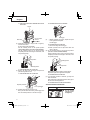
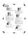
(1) DISCONNECT AIR HOSE FROM NAILER.
REMOVE ALL NAILS FROM NAILER.
□
ALL SCREWS MUST BE TIGHTENED.
If any screws are loose, tighten them.

12
English
□
THE PUSH LEVER AND TRIGGER MUST MOVE
SMOOTHLY.
Do not connect
air hose
Trigger
Push lever
(2) Adjust the air pressure to 70 psi (4.9 bar 5 kgf/cm
2
).
Connect the air hose.
Do not load any nails in the Nailer.
Set the switching device to the upward position
(SINGLE SEQUENTIAL ACTUATION MECHANISM).
(Set the switching device to the upward position
completely as shown in the diagram. Otherwise, it will
not operate properly.)
Upward position
Switching Device
□
THE NAILER MUST NOT LEAK AIR.
(3) Remove the fi nger from the trigger and press the
push lever against the wood.
□
THE NAILER MUST NOT OPERATE.
Depress push lever
Do not pull trigger
(4) Separate the push lever from the wood.
Next, point the nailer downward, pull the trigger and
then wait in that position for 5 seconds or longer.
□
THE NAILER MUST NOT OPERATE.
Pull trigger
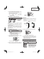
(5)
1
Without touching the trigger, depress the push
lever against the workpiece.
Pull the trigger.
□
THE NAILER MUST OPERATE.
2
Remove the fi nger from the trigger.
□
Nailer operation will end (the driver blade will
return to the top).
(6) Set the switching device to the downward position
(CONTACT ACTUATION MECHANISM).
(Set the switching device to the downward position
completely as shown in the diagram. Otherwise, it will
not operate properly.)
Switching Device
Downward position
With the Nailer off the workpiece, pull the trigger.
Depress the push lever against the workpiece.
□
THE NAILER MUST OPERATE.
(7) If no abnormal operation is observed, you may load
nails in the Nailer.
Drive nails into the workpiece that is the same type to
be used in the actual application.
□
THE NAILER MUST OPERATE PROPERLY.
ADJUSTING AIR PRESSURE
WARNING
●
Do not exceed
120 psi (8.3 bar
8.5 kgf/cm
2
).

13
English
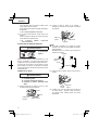
(3) Slide the nail strip into the blade guide.
Nail strip
Blade guide
(4) Confi rm that nail strip is placed with side guide
grooves and Groove properly, then push the
magazine cover forward to be latched.
NAILER OPERATION
Read section titled “SAFETY”(pages 4 – 7).
DANGER
●
Operators and others in work
area MUST wear safety
glasses with side shields
which conforms to ANSI
Z87.1 specifi cations.
WARNING
●
NEVER point tool at yourself or others in
work area.
●
Keep fi ngers AWAY from trigger when not
driving nails to avoid accidental fi ring.
●
Choice of triggering method is important.
Please read and understand “METHODS OF
OPERATION” found below.
●
Before starting work, check the nailing
operation switching device.
This Hitachi nailer includes a nailing
operation switching device.
Before starting work, make sure that the
switching device is properly set.
If the switching device is not set properly, the
nailer will not operate correctly.
●
Never place your face, hands or feet near
fi ring head when using.
●
Do not drive nails on top of other nails or
with Nailer at too steep of an angle; nails can
ricochet and hurt someone.
Adjust the air pressure at recommended
operating pressure 70 – 120 psi (4.9 – 8.3 bar
5 – 8.5 kgf/cm
2
) according to the length of nails and the
hardness of workpiece.
The correct air pressure is the lowest pressure which will
do the job. Using the Nailer at a higher than required air
pressure unnecessarily over stresses the Nailer.
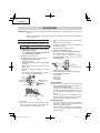
LOADING NAILS
WARNING
●
When loading nails into Nailer,
1) do not pull trigger;
2) do not depress push lever; and
3) keep Nailer pointed downward.
(1) Lightly press the stop lever and gently pull out the
magazine cover.
Stop lever
Magazine cover
Pull out
Press
(2) Set nail strip into the magazine and keep the points of
nails in contact with Groove.
Groove
Nail strip
Magazine
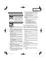
NOTE
●
The nails shown in page 9 can be loaded onto the
side guide groove of the magazine without any
adjustment.
Always keep the points of nails in contact with
Groove.
Magazine
Gap
Side guide
groove
Nail
Groove

14
English
●
Do not drive nails into thin boards or near
corners and edges of workpiece. Nails can be
driven through or away from workpiece and
hit someone.
●
Never drive nails from both sides of a wall
at the same time. Nails can be driven into
and through the wall and hit a person on the
opposite side.
●
Never use Nailer which is defective or
operating abnormally.
●
Do not use Nailer as hammer.
●
Disconnect air hose from Nailer when:
1) turning the adjuster and top cover;
2) attaching or removing the nose cap;
3) it is not in use;
4) leaving work area;
5) moving it to another location;
6) handing it to another person; and
7) changing switching device.
This Hitachi nailer is equipped with a nailer operation
switching device.
Use SINGLE SEQUENTIAL ACTUATION MECHANISM or
CONTACT ACTUATION MECHANISM in accordance with
the work to be performed.
Explanation of the various nailing operations
○
SINGLE SEQUENTIAL ACTUATION MECHANISM:
First, press the push lever against the wood; next,
pull the trigger to drive the nail.
After nailing once, nailing will not be possible again
until the trigger is released and pressed again.
○
CONTACT ACTUATION MECHANISM: First, press
the push lever against the workpiece; next, pull the
trigger to driver the nail. Or,
pull the trigger; next, press the push lever against the
workpiece to drive the nail.
If the trigger is held back, a nail will be driven each
time the push lever is pressed against the wood.
METHODS OF OPERATION
This Nailer is equipped with the push lever and does
not operate unless the push lever is depressed (upward
position).
There are two methods of operation to drive nails with this
Nailer.
They are:
1. Intermittent operation (Trigger fi re):
2. Continuous operation (Push lever fi re):
(1) Intermittent operation (Trigger fi re)
Use the SINGLE SEQUENTIAL ACTUATION
MECHANISM setting.
WARNING
●
For intermittent operation, set the switching
device to the upward position completely.
(i.e. Set to SINGLE SEQUENTIAL ACTUATION
MECHANISM.)
●
To avoid double fi ring or accidental fi ring due
to recoil.
1) Set the switching device to SINGLE
SEQUENTIAL ACTUATION MECHANISM.
2) Pull the trigger rapidly and fi rmly.
1
Set the switching device to the upward position
(to set to SINGLE SEQUENTIAL ACTUATION
MECHANISM).
(Set the switching device to the upward position
completely as shown in the diagram. Otherwise,
it will be set to CONTACT ACTUATION
MECHANISM.)
2
Position the nail outlet on the workpiece with
fi nger off the trigger.
3
Depress the push lever fi rmly until it is completely
depressed.
4
Pull the trigger to drive a nail.
5
Remove fi nger from the trigger.
To continue nailing in a separate location, move the
nailer along the wood, repeating steps
2
-
5
as
required.
Switching Device
1
Upward position
Push lever
Trigger
3
4

15
English
WARNING
●
A nail will fi re each time the trigger is
depressed as long as the push lever remains
depressed.
(2) Continuous operation (Push lever fi re)
Using CONTACT ACTUATION MECHANISM
WARNING
●
To avoid double fi ring or accidental fi ring due
to recoil.
1) Do not press the nailer against the wood
with excessive force.
2) Separate the nailer from the wood as it
recoils after nailing.
1
Set the switching device to the downward position
(to set to CONTACT ACTUATION MECHANISM).
(Set the switching device to the downward
position completely as shown in the diagram.
Otherwise, it will not operate properly.)
2
Pull the trigger with the Nailer off the workpiece.
3
Depress the push lever against the workpiece to
drive a nail.
4
Move the Nailer along the workpiece with a
bouncing motion.
Each depression of the push lever will drive a nail.
As soon as the desired number of nails have been
driven, remove fi nger from the trigger.
Switching Device
1
Downward position
Previously pull the trigger
2
4
Push lever
WARNING
●
Keep your fi nger off the trigger except during
nailing operation, because serious injury
could result if the push lever accidentally
contacts you or others in work area.
●
Keep hands and body away from the
discharge area. This Hitachi nailer may
bounce from the recoil of driving a nail and
unwanted subsequent nail may be driven,
possibly causing injury.
The SINGLE SEQUENTIAL ACTUATION MECHANISM
is for use where precision fastener placement is desired.
The SINGLE SEQUENTIAL ACTUATION MECHANISM
may reduce the possibility of bodily injury to you or others
in the work area compared to the CONTACT ACTUATION
MECHANISM. This is because it is less likely to drive
an unwanted nail if you keep the trigger pulled and
accidentally bump the push lever against yourself or
others.
The SINGLE SEQUENTIAL ACTUATION MECHANISM
may also reduce the speed of operation compared
to the CONTACT ACTUATION MECHANISM. The
SINGLE SEQUENTIAL ACTUATION MECHANISM is
recommended to inexperienced users.
NOTE
●
If all warnings and instructions are followed, safe
operation is possible with two systems: SINGLE
SEQUENTIAL ACTUATION MECHANISM, and
CONTACT ACTUATION MECHANISM.
●
Always handle nails and package carefully. If nails
are dropped, collating bond may be broken, which
will cause mis-feeding and jamming.
●
After nailing:
1) disconnect air hose from the Nailer;
2) remove all nails from the Nailer;
3) supply 5 – 10 drops of Hitachi pneumatic tool
lubricant into the air plug on the Nailer; and
4) open the petcock on the air compressor tank to
drain any moisture.
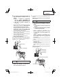
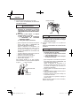
ADJUSTING THE NAILING DEPTH
WARNING
●
When adjusting the Adjuster, be sure to
remove your fi nger from the trigger and
disconnect the air hose from the nailer.
To assure that each nail penetrates to the same depth, be
sure that:

16
English
1) the air pressure to the Nailer remains constant
(regulator is installed and working properly), and
2) the Nailer is always held fi rmly against the workpiece.
If nails are driven too deep or shallow into the workpiece,
adjust the nailing in the following order.
1
DISCONNECT AIR HOSE FROM NAILER.
Adjuster
15
Disconnect
air hose
2
If nails are driven too deep, turn the adjuster to the
shallow side.
Too deep
Turn adjuster
Flush
2
If nails are driven too shallow, turn the adjuster to the
deep side.
Too shallow
Turn adjuster
Flush
2
3
Stop turning the adjuster when a suitable position is
reached for a nailing test.
4
Connect the air hose.
ALWAYS WEAR SAFETY GLASSES.
Perform a nailing test.
5
DISCONNECT AIR HOSE FROM NAILER.
6
Choose a suitable position for the adjuster.
NOTE
●
The nail might not drive deep enough if using high
pressure with the adjuster set upwards (shallow side)
due to factors such as the material hardness or nail
type.
If that happens, reduce pressure and set the adjuster
to lowest position so the nail drives in at a good
position.
CHANGING THE EXHAUST DIRECTION
WARNING
●
When changing the exhaust direction, be
sure to remove your fi nger from the trigger
and disconnect the air hose from the nailer.
The direction of the exhaust vent can be changed by
turning the top cover.
Exhaust vent
Top cover
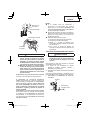
USING THE NOSE CAP
WARNING
●
When detaching or attaching the nose cap,
be sure to remove your fi nger from the trigger
and disconnect the air hose from the nailer.
The nose cap is attached to the push lever tip to protect
the workpiece from scratches or damage. Remove in the
order shown below when not using.
1
DISCONNECT AIR HOSE FROM NAILER.
2
Pull out the nose cap in the direction of the arrow as
shown in the diagram.
○
Attach to the tip of the push lever in the reverse order
of detaching.
Firing head
Nose cap
Push lever
1
Disconnect
air hose
When not using the nose cap, attach to the storage area
in back of the magazine.
Nose cap

17
English
3. WARNING LABEL
Change the WARNING LABEL if missing or
damaged.
A new WARNING LABEL is available from a Hitachi
authorized service center.
Warning
label
4. Maintenance chart (See page 18)
5. Operator troubleshooting (See page 19)
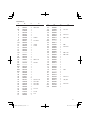
6. Service parts list
A: Item No.
B: Code No.
C: No. Used
D: Remarks
CAUTION
Repair, modifi cation and inspection of Hitachi Power
Tools must be carried out by a Hitachi Authorized
Service Center.
This Parts List will be helpful if presented with the
tool to the Hitachi Authorized Service Center when
requesting repair or other maintenance.
In the operation and maintenance of power tools, the
safety regulations and standards prescribed in each
country must be observed.
MODIFICATIONS
Hitachi Power Tools are constantly being improved
and modifi ed to incorporate the latest technological
advancements.
Accordingly, some parts (i.e. code numbers and/or
design) may be changed without prior notice.
MAINTENANCE
NOTE: The information contained in this Manual is designed to assist you in the safe maintenance of the Nailer.
Some illustrations in this Manual may show details or attachments that diff er from those on your own Nailer.
MAINTENANCE AND INSPECTION
Read section titled “SAFETY” (pages 4 – 7).
WARNING
●
Disconnect air hose and remove all nails
from Nailer when:
1) doing maintenance and inspection; and
2) clearing a jam.
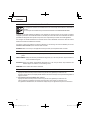
1. Clearing a jam
Remove a jammed nail in the following order:
1
DISCONNECT AIR HOSE.
2
Remove all nails.
3
Release the lock lever and open guide plate.
4
Remove the jammed nail with a slotted-head
screwdriver.
5
Close guide plate and latch.
6
In case of frequent jam, contact a Hitachi
authorized service center.
Guide plate
Lock lever
3
3
1
Disconnect
air hose
Guide plate
2. Storing
○
When not in use for an extended period, apply a thin
coat of the lubricant to the steel parts to avoid rust.
○
Do not store the Nailer in a cold weather environment.
Keep the Nailer in a warm area.
○
When not in use, the Nailer should be stored in a
warm and dry place.
Keep out of reach of children.

18
English
SERVICE AND REPAIRS
WARNING
●
Only service personnel trained by Hitachi,
distributor or employer shall repair the Nailer.
●
Use only parts supplied or recommended by
Hitachi for repair.
All quality Nailers will eventually require servicing or
replacement of parts because of wear from normal use.
NOTE: Specifi cations are subject to change without any
obligation on the part of HITACHI.
Maintenance chart
ACTION WHY HOW
Drain air line fi lter daily. Prevent accumulation of moisture
and dirt.
Open manual petcock.
Keep lubricator fi lled. Keep the Nailer lubricated. Fill with Hitachi pneumatic tool
lubricant.
Clean fi lter element — then blow air
through fi lter in direction opposite to
normal fl ow.
Prevent clogging of fi lter with dirt. Follow manufacturer’s instructions.
Clean magazine and feeder
mechanism.
Prevent a jam. Blow clean daily.
Keep push lever working properly. Promote operator safety and effi cient
Nailer operation.
Blow clean daily.
Lubricate the Nailer after nailing. Extend the Nailer life. Supply 5 – 10 drops of lubricant into
the Nailer.
Drain air compressor. Keep the Nailer operated properly. Open petcock on air compressor
tank.

19
English
Operator troubleshooting
Most minor problems can be resolved quickly and easily using the table below.
If problems persist, contact a Hitachi authorized service center for assistance.
PROBLEM CHECK METHOD CORRECTION
Nailer operates, but no nail is driven. Check for a jam. Clear a jam page 17.
Nail feeder damaged? Replace nail feeder.
Feed spring weakened or damaged? Replace feed spring.
Check for proper nails. Use only recommended nails.
Weak drive.
Slow to cycle.
Check air pressure. Increase air pressure.
(Do not exceed 120 psi
(8.3 bar 8.5 kgf/cm
2
))
Check position of nailing depth
adjuster.
Readjust per page 15.
—————— Use Hitachi pneumatic tool lubricant.
Driver blade worn? Contact Hitachi for replacement.
Piston O-ring worm or damaged?
Drives too deep. Check air pressure. Reduce air pressure.
(Adjust 70 – 120 psi
(4.9 – 8.3bar 5 – 8.5 kgf/cm
2
))
Check position of nailing depth
adjustment.
Readjust per page 15.
Skipping nails.
Intermittent feed.
Check for proper nails. Use only recommended
Nail feeder damaged? Replace nail feeder.
Feed spring weakened or damaged? Replace feed spring.
Piston O-ring worn or damaged? Contact Hitachi for replacement.
Nails jam.
Driven nail is bent.
Check for proper nails. Use only recommended nails.
Driver blade worn? Contact Hitachi for replacement.
Drives properly during normal
operation, but does not drive fully at
faster nailing speeds.
Check inside diameter of air hose. Use larger air hose.

20
Français
INFORMATION IMPORTANTE DE SÉCURITÉ
Lire et bien assimiler toutes les étiquettes de l’outil ainsi que toutes les instructions de fonctionnement,
les consignes de sécurité et les avertissements de ce mode d’emploi avant d’utiliser ou d’entretenir ce
cloueur.
Le non respect des avertissements pourrait entraîner la MORT ou des BLESSURES GRAVES.
La plupart des accidents résultant de l’utilisation ou de l’entretien des cloueurs sont dus au non respect de certaines
consignes et précautions de sécurité élémentaires. Un accident peut souvent être évité en reconnaissant une situation
potentiellement dangereuse avant qu’elle ne se produise, et en respectant les procédures de sécurité applicables.
Les consignes de sécurité élémentaires sont données dans la section “SECURITE” du manuel et dans les sections
relatives aux instructions d’utilisation et d’entretien.
Les dangers à éviter pour empêcher tout risque de blessures ou de dommage de l’outil sont identifi és par les mots
DANGER et AVERTISSEMENT, sur le cloueur et dans ce manuel.
NE JAMAIS utiliser ce cloueur pour des applications autres que celles qui sont spécifi ées dans ce manuel.
DEFINITION DES MOTS DE SIGNALISATION
DANGER indique une situation imminente dangereuse qui, si elle n’est pas évitée, entraînera la mort ou des blessures
graves.
AVERTISSEMENT indique une situation potentiellement dangereuse qui, si elle n’est pas évitée, risque d’entraîner la
mort ou des blessures graves.
ATTENTION indique une situation potentiellement dangereuse qui, si elle n’est pas évitée, risque d’entraîner des
blessures légères ou modérées, ou d’endommager l’outil.
REMARQUE met en relief les informations essentielles.
EXPLICATION DE L’ACTION DE CLOUAGE DU CLOUEUR HITACHI
○
MÉCANISME DE DÉCLENCHEMENT SÉQUENTIEL UNIQUE:
Appuyer tout d’abord le levier-poussoir contre le bois, puis tirer sur la gâchette pour enfoncer le clou.
Quand un clou est enfoncé, il n’est plus possible d’enfoncer un autre clou tant que l’on n’a pas relâché la gâchette et
appuyé à nouveau.
○
MÉCANISME DE DÉCLENCHEMENT PAR CONTACT:
Appuyer tout d’abord le levier-poussoir contre le bois, puis tirer sur la gâchette pour enfoncer le clou.
Tirer tout d’abord sur la gâchette, puis appuyer le levier-poussoir contre le bois pour enfoncer le clou.
Si la gâchette est maintenue tirée, un clou s’enfonce chaque fois que l’on appuie le levier-poussoir contre le bois.
La page est en cours de chargement...
La page est en cours de chargement...
La page est en cours de chargement...
La page est en cours de chargement...
La page est en cours de chargement...
La page est en cours de chargement...
La page est en cours de chargement...
La page est en cours de chargement...
La page est en cours de chargement...
La page est en cours de chargement...
La page est en cours de chargement...
La page est en cours de chargement...
La page est en cours de chargement...
La page est en cours de chargement...
La page est en cours de chargement...
La page est en cours de chargement...
La page est en cours de chargement...
La page est en cours de chargement...
La page est en cours de chargement...
La page est en cours de chargement...
La page est en cours de chargement...
La page est en cours de chargement...
La page est en cours de chargement...
La page est en cours de chargement...
La page est en cours de chargement...
La page est en cours de chargement...
La page est en cours de chargement...
La page est en cours de chargement...
La page est en cours de chargement...
La page est en cours de chargement...
La page est en cours de chargement...
La page est en cours de chargement...
La page est en cours de chargement...
La page est en cours de chargement...
La page est en cours de chargement...
La page est en cours de chargement...
La page est en cours de chargement...
La page est en cours de chargement...
La page est en cours de chargement...
La page est en cours de chargement...
La page est en cours de chargement...
La page est en cours de chargement...
La page est en cours de chargement...
La page est en cours de chargement...
-
 1
1
-
 2
2
-
 3
3
-
 4
4
-
 5
5
-
 6
6
-
 7
7
-
 8
8
-
 9
9
-
 10
10
-
 11
11
-
 12
12
-
 13
13
-
 14
14
-
 15
15
-
 16
16
-
 17
17
-
 18
18
-
 19
19
-
 20
20
-
 21
21
-
 22
22
-
 23
23
-
 24
24
-
 25
25
-
 26
26
-
 27
27
-
 28
28
-
 29
29
-
 30
30
-
 31
31
-
 32
32
-
 33
33
-
 34
34
-
 35
35
-
 36
36
-
 37
37
-
 38
38
-
 39
39
-
 40
40
-
 41
41
-
 42
42
-
 43
43
-
 44
44
-
 45
45
-
 46
46
-
 47
47
-
 48
48
-
 49
49
-
 50
50
-
 51
51
-
 52
52
-
 53
53
-
 54
54
-
 55
55
-
 56
56
-
 57
57
-
 58
58
-
 59
59
-
 60
60
-
 61
61
-
 62
62
-
 63
63
-
 64
64


Hitachi NT 32AE2 (S) Instruction And Safety Manual
- Catégorie
- Cloueuse
- Taper
- Instruction And Safety Manual
- Ce manuel convient également à
dans d''autres langues
- English: Hitachi NT 32AE2 (S)
- español: Hitachi NT 32AE2 (S)
Documents connexes
-
Hitachi NV 65AN Instruction And Safety Manual
-
Hitachi NT 50AE2 Manuel utilisateur
-
-
-
-
-
-
-
-