
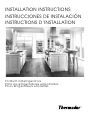
INSTALLATION INSTRUCTIONS
INSTRUCCIONES DE INSTALACIÓN
INSTRUCTIONS D’INSTALLATION
For Built-in Refrigerators
Para los refrigeradores empotrados
Pour réfrigérateurs encastrés

2
INSTALLATION INSTRUCTIONS
INSTRUCCIONES DE INSTALACIÓN
INSTRUCTIONS D’INSTALLATION
For Built-in Refrigerators
Para los refrigeradores empotrados
Pour réfrigérateurs encastrés
Congratulations on your recent THERMADOR
®
purchase! Whether you are a dedicated chef or simply a connoisseur of the art of
cooking, owning a THERMADOR
®
kitchen is the ultimate expression of personal style, good taste and an appreciation for the complete
culinary experience. Our award-winning products have been empowering culinary enthusiasts for more than eleven decades.
Before you begin using your new THERMADOR
®
product, please take a moment to review the Use and Care Guide. You will find the
answers to all your questions as well as some very important safety information. Pay special attention to the “Important Safety
Instructions” located at the beginning of the manual. Your THERMADOR
®
product is ready and waiting to be used for your next gourmet
creation! Our products are handcrafted with the highest quality authentic materials to ensure years of reliable service. In the unlikely
event that you have a service question, please have your model and serial numbers of your product available.
We realize that you have made a considerable investment in your kitchen. Please feel free to share your THERMADOR
®
kitchen photos
and remodeling stories with us. Follow us on Twitter or post your kitchen photos on Facebook. We would love to hear from you!
THERMADOR
®
wishes you many years of creative cooking.
¡Enhorabuena por la reciente compra de su THERMADOR
®
! Ya sea usted un gran jefe de cocina o un simple aficionado del arte
culinario, el hecho de poseer una cocina THERMADOR® es la máxima expresión de su estilo personal, de su buen gusto y de su
apreciación de una experiencia culinaria completa. Nuestros premiados productos han permitido al entusiasta de la cocina explorar
este mundo desde hace más de once décadas.
Antes de comenzar a utilizar su nuevo producto THERMADOR
®
, tómese un momento para echar un vistazo al Manual de uso y
cuidado. Encontrará las respuestas a todas sus preguntas, además de información muy importante relativa a la seguridad. Ponga
especial atención a las “Instrucciones de seguridad importantes”, situadas al principio del manual. ¡Su producto THERMADOR
®
está
listo y sólo espera a que usted lo use para su próxima creación gastronómica! Nuestros productos se fabrican a mano con materiales
auténticos de alta calidad a fin de garantizar años de servicio fiable. En el caso improbable de que usted tenga una pregunta relativa al
servicio, tenga a mano el número de serie y de modelo de su producto.
Nos damos cuenta de que usted invirtió una suma considerable en su cocina. No dude en compartir con nosotros las fotos de su
cocina THERMADOR
®
y anécdotas acerca de la remodelación de su cocina. Síganos en Twitter o publique fotos de su cocina en
Facebook. ¡Estaremos encantados de tener noticias suyas!
¡THERMADOR
®
le desea muchos años de gastronomía creativa!
Félicitations pour votre récent achat THERMADOR
®
! Que vous soyez un chef enthousiaste ou un simple connaisseur de l’art culinaire, le
fait de posséder une cuisine THERMADOR
®
représente l’expression untime de votre style personnel, de votre bon goût et de votre envie
de vivre une expérience culinaire complète. Nos produits primés permettent à des adeptes de gastronomie fine d’atteindre de
nouveaux sommets depuis plus de onze décennies.
Avant de commencer à utiliser votre nouveau produit THERMADOR
®
, veuillez prendre un moment pour examiner ce guide d’utilisation
et d’entretien. Vous trouverez des réponses à toutes vos questions ainsi que quelques renseignements essentiels en matière de
sécurité. Portez une attention particulière aux “Instructions de sécurité importantes” se trouvant au début du guide. Votre produit
THERMADOR
®
est prêt et n’attend plus que vous l’utilisiez pour votre prochaine création gastronomique!
Nos produits sont fabriqués à la main avec des matériaux authentiques de la plus haute qualité afin d’assurer des années de service
fiable. Dans l’éventualité improbable où vous auriez une question relativement à l’entretien, veuillez avoir à la portée de la main le
numéro de série et de modèle de votre produit.
Nous sommes conscients que vous avez investi une somme considérable dans votre cuisine. N’hésitez pas à partager avec nous les
photos de votre cuisine THERMADOR
®
et les anecdotes relatives au remodelage de votre cuisine. Suivez-nous sur Twitter ou affichez
des photos de votre cuisine sur Facebook. Nous serions ravis d’avoir de vos nouvelles!
THERMADOR
®
vous souhaite de nombreuses années de gastronomie créative.
Model/Modelo/Modèle :
T42BR810NS
T48BR810NS
T42BR820NS
T48BR820NS
T42BD810NS
T48BD810NS
T42BD820NS
T48BD820N

3
TABLE OF CONTENTS
REFRIGERATOR SAFETY .............................................................4
DESIGN SPECIFICATIONS............................................................5
Models..........................................................................................5
INSTALLATION REQUIREMENTS................................................6
Tools and Parts ............................................................................6
Location Requirements................................................................6
Electrical Requirements ...............................................................7
Water Supply Requirements........................................................7
Tipping Radius .............................................................................8
Product Dimensions.....................................................................8
Door Swing Dimensions...............................................................9
Stainless Steel Series Side Panels ..............................................9
INSTALLATION INSTRUCTIONS ................................................10
Unpack the Refrigerator.............................................................10
Reduce Tipping Radius..............................................................11
Move the Refrigerator into House..............................................11
Install Anti-Tip Boards................................................................11
Connect the Water Supply.........................................................12
Plug in Refrigerator.....................................................................13
Move Refrigerator to Final Location...........................................13
Level and Align Refrigerator.......................................................14
Adjust Doors...............................................................................14
Install Side Panel........................................................................15
Install Base Grille........................................................................16
Complete Installation..................................................................16
Water System Preparation .........................................................17
ÍNDICE
SEGURIDAD DEL REFRIGERADOR...........................................18
ESPECIFICACIONES DE DISEÑO ..............................................19
Modelos......................................................................................19
REQUISITOS DE INSTALACIÓN.................................................20
Herramientas y piezas................................................................20
Requisitos de ubicación.............................................................20
Requisitos eléctricos..................................................................21
Requisitos del suministro de agua.............................................22
Arco de vuelco ...........................................................................22
Medidas del producto................................................................22
Medidas de oscilación de las puertas .......................................23
Paneles laterales de la serie de acero inoxidable......................24
INSTRUCCIONES DE INSTALACIÓN.........................................25
Desempaque el refrigerador ......................................................25
Cómo reducir el arco de vuelco.................................................25
Cómo hacer entrar el refrigerador en la casa ............................25
Cómo instalar los tableros antivuelco........................................26
Conexión del suministro de agua ..............................................26
Cómo enchufar el refrigerador...................................................28
Cómo mover el refrigerador a su ubicación final.......................28
Nivelación y alineamiento del refrigerador.................................28
Ajuste las puertas.......................................................................29
Cómo instalar el panel lateral.....................................................30
Cómo instalar la rejilla de la base ..............................................31
Cómo terminar la instalación .....................................................31
Preparación del sistema de agua ..............................................32
TABLE DES MATIÈRES
SÉCURITÉ DU RÉFRIGÉRATEUR ..............................................33
SPÉCIFICATIONS DE DESIGN....................................................34
Modèles......................................................................................34
EXIGENCES D’INSTALLATION...................................................35
Outillage et pièces......................................................................35
Exigences d’emplacement.........................................................35
Spécifications électriques..........................................................37
Spécifications de l’alimentation en eau.....................................37
Rayon de basculement ..............................................................38
Dimensions du produit...............................................................38
Dimensions pour l'ouverture des portes....................................39
Panneaux latéraux de la série de panneaux en
acier inoxydable .........................................................................39
INSTRUCTIONS D’INSTALLATION.............................................40
Déballage du réfrigérateur..........................................................40
Réduction du rayon de basculement.........................................41
Faire entrer le réfrigérateur dans le domicile .............................41
Installation de planches antibasculement..................................41
Raccordement à l’alimentation en eau ......................................42
Brancher le réfrigérateur.............................................................43
Déplacement du réfrigérateur à l'emplacement final.................44
Réglage de l'aplomb et alignement du réfrigérateur .................44
Ajustement des portes ...............................................................45
Installation du panneau latéral ...................................................45
Installation de la grille de la base...............................................46
Achever l’installation ..................................................................46
Préparation du système d’eau...................................................47

4
REFRIGERATOR SAFETY
You can be killed or seriously injured if you don't immediately
You
can be killed or seriously injured if you don't
follow
All safety messages will tell you what the potential hazard is, tell you how to reduce the chance of injury, and tell you what can
happen if the instructions are not followed.
Your safety and the safety of others are very important.
We have provided many important safety messages in this manual and on your appliance. Always read and obey all safety
messages.
This is the safety alert symbol.
This symbol alerts you to potential hazards that can kill or hurt you and others.
All safety messages will follow the safety alert symbol and either the word “DANGER” or “WARNING.”
These words mean:
follow instructions.
instructions.
DANGER
WARNING
WARNING
Tip Over Hazard
Refrigerator is top heavy and tips easily when not
completely installed.
Keep doors taped closed until refrigerator is
completely installed.
Use two or more people to move and install
refrigerator.
Failure to do so can result in death or serious injury.

5
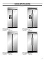
DESIGN SPECIFICATIONS
Models
Stainless Steel Masterpiece Series
Side by Side Dispensing
T42BD810NS T48BD810NS
Stainless Steel Professional Series
Side by Side Dispensing
T42BD820NS T48BD820NS
Stainless Steel Masterpiece Series
Side by Side Non-Dispensing
T42BR810NS T48BR810NS
Stainless Steel Professional Series
Side by Side Non-Dispensing
T42BR820NS T48BR820NS

6
INSTALLATION REQUIREMENTS
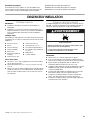
Tools and Parts
IMPORTANT:
■ Installer: Leave Installation Instructions with the homeowner.
■ Homeowner: Keep Installation Instructions for future
reference. Save these Installation Instructions for the local
electrical inspector’s use.
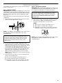
Tools Needed
Gather the required tools and parts before starting installation.
Read and follow the instructions provided with any tools listed
here.
Parts Needed
■ #8 x 3" (7.6 cm) wood screws (longer screws may be needed) (6)
■ 2" x 4" x 32" (5 cm x 10 cm x 81 cm) wood board(s) (1 or 2)
■ If you are connecting the water line directly to copper tubing
and not to a shutoff valve, you need a ferrule, a union, and a
¹⁄₄" (6.35 mm) compression fitting.
Location Requirements
The refrigerator can be recessed in an opening between cabinets
or installed at the end of a cabinet run using a side panel to
enclose the refrigerator.
IMPORTANT:
■ Observe all governing codes and ordinances.
■ It is recommended that you do not install the refrigerator near
an oven, radiator, or other heat source.
■ Do not install in a location where the temperature will fall
below 55°F (13°C).
■ Floor must support the refrigerator weight, more than 600 lbs
(272 kg), door panels and contents of the refrigerator.
■ Ceiling height must allow for side tipping radius. See “Tipping
Radius.”
■ Location should permit door to open fully. See “Door Swing
Dimensions.”
■ Location must permit top grille removal. See “Opening
Dimensions.”
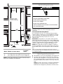
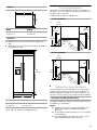
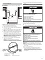
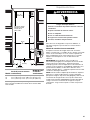
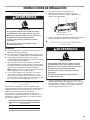
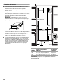
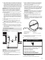
Opening Dimensions
■ To avoid tipping during use, the solid soffit must be within 1"
(2.5 cm) maximum above the refrigerator. If the solid soffit is
higher than 1" (2.5 cm) or one is not available, then the
refrigerator must be braced.
If the anti-tip boards are needed, they must be attached to
the rear wall studs 80" to 90" (203 cm to 229 cm) above the
floor. See “Install Anti-Tip Boards” for more information.
NOTE: A clearance of ¹⁄₂" (1.3 cm) must be maintained above
the top grille in order for the top grille to be removed.
■ A grounded 3 prong electrical outlet should be located within
a specified number of inches from the right-hand side
cabinets or end panel. See the chart following the graphic for
the number of inches required for your model. For more
information, see “Electrical Requirements.”
■ The water shutoff should be located in the base cabinet on
either side of the refrigerator or some other easily accessible
area. If the water shutoff valve is not in the cabinets, the
plumbing for the water line can come through the floor or the
back wall. See “Water Supply Requirements” for more
information.
Handle Kits
For use with Stainless Steel models. You can purchase a handle
type other than that provided with your model. See your dealer for
details.
PROHNDL160—Pro Handle Kit
PROHNDL165—Designer Pro Handle Kit
MASTHNDL55—Masterpiece Handle Kit
■ Cordless drill
■ Drill bits
■ Adjustable
wrenches (2)
■ Phillips screwdriver
■ Small level
■ Appliance dolly
■ Tor x
®†
T27 screwdriver
■ ¹¹⁄₃₂" nut driver
■ ³⁄₈" and ¹⁄₂" open-end wrenches
■ ⁵⁄₃₂" hex key
■ ¹⁄₄" and ⁵⁄₁₆" socket drivers
■ Tape measure
■ Utility knife
†®TORX is a registered trademark of Saturn Fasteners, Inc.
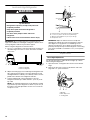
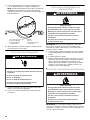
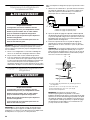
WARNING
Explosion Hazard
Keep flammable materials and vapors, such as
gasoline, away from refrigerator.
Failure to do so can result in death, explosion, or fire.
¹⁄₂"
(1.3 cm)

7
NOTE: Flooring under refrigerator must be at same level as the
room. Face of cabinetry must be plumb.
Electrical Requirements
Before you move your refrigerator into its final location, it is
important to make sure you have the proper electrical
connection.
Recommended Grounding Method
A 115 volt, 60 Hz., AC only, 15- or 20-amp fused, grounded
electrical supply is required. It is recommended that a separate
circuit serving only your refrigerator be provided. Use an outlet
that cannot be turned off by a switch. Do not use an
extension cord.
IMPORTANT: If this product is connected to a GFCI (Ground
Fault Circuit Interrupter) protected outlet, nuisance tripping of the
power supply may occur, resulting in loss of cooling. Food quality
and flavor may be affected. If nuisance tripping has occurred,
and if the condition of the food appears poor, dispose of it.
NOTE: Before performing any type of installation, cleaning, or
removing a light bulb, remove the top grille and turn the master
power switch to OFF or disconnect power at the circuit breaker
box.
When you are finished, turn ON the master power switch or
reconnect power at the circuit breaker box. Then reset the control
to the desired setting.
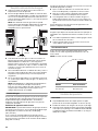
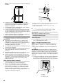
Water Supply Requirements
■ All installations must meet local plumbing code requirements.
■ The water shutoff should be located in the base cabinet on
either side of the refrigerator or some other easily accessible
area. The right-hand side is recommended. The access hole
through the cabinet must be within ¹⁄₂" (12.7 mm) of the rear
wall.
NOTE: If the water shutoff valve is in the back wall behind the
refrigerator, it must be at an angle so that the tube is not
kinked when the refrigerator is pushed into its final location.
Model Width A (as shown above)
Dimension B
(as shown
above)
36
42
48
35¹⁄₂" (90.2 cm) to 35³⁄₄" (90.8 cm)
41¹⁄₂" (105.4 cm) to 41³⁄₄" (106.1 cm)
47¹⁄₂" (120.7 cm) to 47³⁄₄" (121.3 cm)
4" (10.2 cm)
10" (25.4 cm)
16" (40.6 cm)
80" - 90"
(203-229 cm)
6"
(15.2 cm)
83¹⁄₂" (212.1 cm) min.
84
³⁄₄" (215 cm) max.
to bottom of solid soffit
24"
(60.96 cm) min.
1"
(2.54 cm)
77"
(196 cm)
6"
(15.2 cm)
6"
(15.2 cm)
A
Width
(see chart following)
B
Dimension
Electrical Shock Hazard
Plug into a grounded 3 prong outlet.
Do not remove ground prong.
Do not use an adapter.
Do not use an extension cord.
Failure to follow these instructions can result in death,
fire, or electrical shock.
WARNING

8
■ If the water shutoff valve is not in the cabinets, the plumbing
for the water line can come through the floor. A ¹⁄₂" (12.7 mm)
hole for plumbing should be drilled at least 6" (15.2 cm) from
the right or left hand side cabinet or panel. On the floor, the
hole should be no more than 1" (2.54 cm) away from the back
wall. See “Connect the Water Supply.”
■ If additional tubing is needed, use copper tubing and check
for leaks. Install the copper tubing only in areas where the
household temperatures will remain above freezing.
■ Do not use a piercing-type or ³⁄₁₆" (4.76 mm) saddle valve
which reduces water flow and clogs more easily.
NOTE: Your refrigerator dealer has a kit available with a ¹⁄₄"
(6.35 mm) saddle-type shutoff valve, a union, and copper
tubing. Before purchasing, make sure a saddle-type valve
complies with your local plumbing codes.
Water Pressure
A cold water supply with water pressure between 30 and 120 psi
(207 and 827 kPa) is required to operate the water dispenser and
ice maker. If you have questions about your water pressure, call a
licensed, qualified plumber.
Reverse Osmosis Water Supply
IMPORTANT: The pressure of the water supply coming out of a
reverse osmosis system going to the water inlet valve of the
refrigerator needs to be between 30 and 120 psi
(207 and 827 kPa).
If a reverse osmosis water filtration system is connected to your
cold water supply, the water pressure to the reverse osmosis
system needs to be a minimum of 40 to 60 psi (276 to 414 kPa).
If the water pressure to the reverse osmosis system is less than
40 to 60 psi (276 to 414 kPa):
■ Check to see whether the sediment filter in the reverse
osmosis system is blocked. Replace the filter if necessary.
■ Allow the storage tank on the reverse osmosis system to refill
after heavy usage.
■ If your refrigerator has a water filter cartridge, it may further
reduce the water pressure when used in conjunction with a
reverse osmosis system. Remove the water filter cartridge.
If you have questions about your water pressure, call a licensed,
qualified plumber.
Tipping Radius
Be sure there is adequate ceiling height to stand the refrigerator
upright when it is moved into place.
■ The dolly wheel height must be added to the tipping radius
when a dolly is used.
■ If needed, the tipping radius can be reduced. See “Reduce
Tipping Radius.”
Side Tipping Radius
The side tipping radius varies depending upon the width of the
model. Use the chart provided to determine the side tipping
radius.
NOTE: Tip on side only.
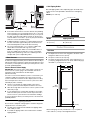
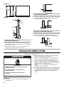
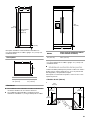
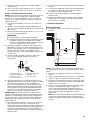
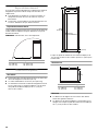
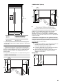
Product Dimensions
Side View
■ The depth from the front of the top grille to the back of the
refrigerator cabinet is 25¹⁄₈" (64 cm).
■ The power cord is 84" (61 cm) long.
■ The water line attached to the back of the refrigerator is 5 ft
(1.5 m) long. Height dimensions are shown with leveling legs
extended ¹⁄₈" (3 mm) below the rollers.
*When leveling legs are fully extended to 1¹⁄₄" (3.2 cm) below
rollers, add 1¹⁄₈" (2.9 cm) to the height dimensions.
24"
(60.96 cm) min.
1"
(2.54 cm)
6"
(15.2 cm)
6"
(15.2 cm)
6"
(15.2 cm)
Model Tipping Radius A
42" (106 cm)
48" (122 cm)
93" (236.2 cm)
96" (243.8 cm)
A
A
23¹⁄₂"
(59.7 cm)
84" (213.4 cm)
Power Cord
*83³⁄₈"
(211.8 cm)
*3
¹⁄₂" (8.9 cm)

9
Top View
Front View
■ Width dimensions were measured from trim edge to trim
edge.
■ Height dimensions are shown with leveling legs extended ¹⁄₈"
(3 mm) below the rollers.
*When leveling legs are fully extended to 1¹⁄₄" (32 mm) below
rollers, add 1¹⁄₈" (29 mm) to the height dimensions.
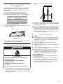
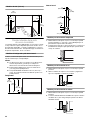
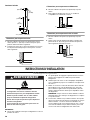
Door Swing Dimensions
The location must permit both doors to open to a minimum of
90°. Allow 4¹⁄₂" (11.4 cm) minimum space between the side of the
refrigerator and a corner wall.
To adjust the door swing, see “Adjust Doors.”
42" (106 cm) Models
48" (122 cm) Models
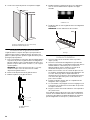
Stainless Steel Series Side Panels
Custom side panels may be needed when not enough space is
available to have cabinets on both sides of the refrigerator or
when the refrigerator is placed at the end of a cabinet run. You
may choose an Inset, Flush, or Recessed Inset panel installation.
Refrigerator and Side Trim Dimensions
The width and height of a side panel are determined by the type
of installation you are planning.
NOTES:
■ The dimensions shown are actual product dimensions
and may not reflect the needed panel installation
dimensions.
■ The side panel should be a minimum of ½" (1.27 cm) thick
to avoid warping.
■ If the opening depth is 25" (63.5 cm) or more, you may
want to install a support board on rear wall.
Model Width A
42" (106 cm)
48" (122 cm)
41" (104 cm)
47" (119 cm)
Model Width A (Trim edge to trim edge)
42" (106 cm)
48" (122 cm)
42¹⁄₄" (107 cm)
48¹⁄₄" (123 cm)
25¹⁄₈"
(64 cm)
A
*83³⁄₈"
(211.8 cm)
A
(see chart following)
130˚
130˚
90˚
90˚
110˚
110˚
47⁷⁄₈"
(121.6 cm)
41¹⁄₂"
(105.4 cm)
16
⁷⁄₈"
(42.9 cm)
12
⁵⁄₈"
(32.1 cm)
37
¹⁄₄"
(94.6 cm)
41
³⁄₈"
(105.1 cm)
130˚
130˚
90˚
90˚
110˚
110˚
51³⁄₈"
(130.5 cm)
44"
(111.8 cm)
19
¹⁄₄"
(48.9 cm)
14
³⁄₈"
(36.5 cm)
39"
(99.1 cm)
43
⁷⁄₈"
(111.4 cm)

10
Refrigerator
Side Trim
Inset Installation Dimensions
1. Measure the distance from point A (as shown) to the back
wall. Add ⁷⁄₃₂" (5.6 mm) to this measurement to allow the side
panel to fit into the trim.
2. If the panel is more than ¹⁄₄" (6.35 mm) thick, rout the front
edge to allow the side panel to fit into the trim.
Flush Installation Dimensions
1.
Measure the distance from point A (as shown) to the back wall.
2. Attach the support board with a screw or adhesive that is
compatible with aluminum and wood.
Recessed Inset Installation Dimensions
1.
Measure the distance from point A
(as shown) to the back wall.
2. Rout the front edge of the support board or attach a ¹⁄₄"
(6.35 mm) board to hold the panel in the cabinet side trim.
INSTALLATION INSTRUCTIONS
Unpack the Refrigerator
IMPORTANT:
■ Do not remove the film covering until the refrigerator is in its
operating location.
■ All four leveling legs must contact the floor to support and
stabilize the full weight of the refrigerator.
■ Keep the cardboard shipping piece or plywood under the
refrigerator until it is installed in the operating location.
1. Remove and save the literature package bag taped to the
side of the refrigerator and the parts bag behind the grille.
Remove the four brackets (two on each side) that attach the
shipping base to the refrigerator bottom.
NOTE: Do not remove tape and door bracing until the
refrigerator is in its final location.
2. If necessary, reduce the tipping radius. See “Tipping Radius”
for ceiling height requirements or “Reduce Tipping Radius”
for step-by-step instructions. If you do not need to reduce the
tipping radius, proceed to “Move the Refrigerator into
House.”
24¹⁄₈"
(61.3 cm)
23
¹⁄₂"
(59.7 cm)
23¹¹⁄₁₆"
(60.3 cm)
¹¹⁄₆₄"
(4.5 mm)
¹⁄₄"
(6.35 mm)
³⁄₁₆"
(4.7 mm)
⁷⁄₃₂"
(5.5 mm)
¹³⁄₃₂" (10 mm)
⁵⁄₈"
(15.7 mm)
A
A
A
WARNING
Tip Over Hazard
Refrigerator is top heavy and tips easily when not
completely installed.
Keep doors taped closed until refrigerator is
completely installed.
Use two or more people to move and install
refrigerator.
Failure to do so can result in death or serious injury.

11
Reduce Tipping Radius
(if required)
Before bringing the refrigerator into the home, be sure there is
adequate ceiling height to stand the refrigerator upright. See
“Tipping Radius” in the “Installation Requirements” section for
more information.
If you do not have adequate ceiling height to stand the
refrigerator upright, the tipping radius can be reduced by
removing the top grille and side trims (see the following chart).
1. Grasp both ends of the top grille.
2. Push the top grille straight up; then pull straight out. Lay the
grille on a soft surface.
3. Remove the six screws attaching each cabinet side trim to
the refrigerator and remove the side trims.
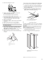
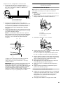
Move the Refrigerator into House
1. Place an appliance dolly under the left side of the refrigerator
as shown. Place the corner posts from the packing materials
over the trims and handles as appropriate to avoid damage.
Slowly tighten the strap.
NOTE: Pass the dolly strap under the handle.
2. Place pieces of the shipping carton on the floor when rolling
the dolly and refrigerator into the house. Move the refrigerator
close to the built-in opening.
3. Place top of cardboard carton or plywood under refrigerator.
4. Stand the refrigerator up. First, place the left bottom edge of
the refrigerator on the floor, stand the refrigerator upright and
then lower the right-hand side of the refrigerator to the floor.
5. Reassemble the trim and top grille after the dolly has been
removed from the refrigerator.
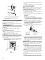
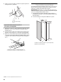
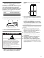
Install Anti-Tip Boards
IMPORTANT:
■ To avoid tipping during use, the solid soffit must be within
1" (2.5 cm) maximum above the refrigerator. If the solid soffit
is higher than 1" (2.5 cm) or one is not available, then the
refrigerator must be braced.
■ It is recommended that board(s) be installed before the
refrigerator is installed.
■ Board(s) must be long enough to fully cover the width of the
compressor cover.
■ Locate the board(s) so the bottom surface(s) of the board(s)
is(are) 84" (213 cm) from the floor.
■ During installation, raise the refrigerator up so there is
¹⁄₄" (6.35 mm) maximum between the top of the refrigerator
and the bottom of the anti-tip board(s). Do not crush the
compressor cover when raising the rear leveling legs.
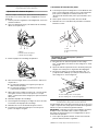
To Install Anti-tip Boards
1. Mark the stud locations on rear wall 80" to 90" (203 cm to
229 cm) above floor.
2. Securely attach one or two 2" x 4" x 32" (5 cm x 10 cm x
81 cm) boards to wall studs behind refrigerator. Use six
#8 x 3" (7.6 cm) (or longer) wood screws. The wood screws
must be screwed into the studs at least 1½" (3.8 cm). The
board(s) must overlap the compressor cover.
Model Reduced Tipping Radius
36 88" (223.5 cm)
42 88¹⁄₂" (224.8 cm)
48 89¹⁄₄" (226.7 cm)
A. Top grille
B. Cabinet side trim
B BA
WARNING
Tip Over Hazard
Refrigerator is top heavy and tips easily when not
completely installed.
Keep doors taped closed until refrigerator is
completely installed.
Use two or more people to move and install
refrigerator.
Failure to do so can result in death or serious injury.

12
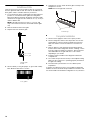
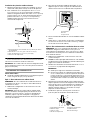
Connect the Water Supply
Read all directions before you begin.
IMPORTANT: If you turn the refrigerator on before the water line
is connected, turn the ice maker OFF.
Connect to Water Line
Parts Needed:
■ Minimum 7 ft (2.13 m) flexible, codes approved water
supply line
Style 1—Shutoff Valve Connection
NOTE: If your water line connection does not look like Style 1,
see “Style 2—Copper Line Connection.”
1. Unplug refrigerator or disconnect power supply.
IMPORTANT: Before attaching the tubing to shutoff valve, flush
the main water supply line to remove particles and air in the water
line. Allow enough flow so that water becomes clear. Flushing the
water line may help avoid filters and/or water valves from
becoming clogged.
2. Connect the flexible, codes approved water supply line to the
water shutoff valve by threading the provided nut onto the
shutoff valve as shown.
3. Place the end of the tubing into a bucket, and turn shutoff
valve ON.
4. Check for leaks. Tighten any nuts or connections (including
connections at the valve) that leak.
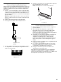
Style 2—Copper Line Connection
NOTE: If there is a water supply line that meets the specifications
in “Water Supply Requirements,” proceed to “Connecting to
Refrigerator.” If not, use the following instructions to connect to
the household cold water supply.
1. Unplug refrigerator or disconnect power.
2. Turn OFF main water supply. Turn ON nearest faucet long
enough to clear line of water.
3. Locate a ½" to 1¹⁄₄" (1.3 cm to 3.2 cm) vertical cold water pipe
near the refrigerator.
IMPORTANT:
■ Make sure it is a cold water pipe.
■ Horizontal pipe will work, but drill on the top side of the
pipe, not the bottom. This will help keep water away from
the drill and keep normal sediment from collecting in the
valve.
4. Determine the length of copper tubing you need. Measure
from the connection on the refrigerator to the water pipe. Add
7 ft (2.1 m) to allow for cleaning. Use ¹⁄₄" (6.35 mm) O.D.
(outside diameter) copper tubing. Be sure both ends of
copper tubing are cut square.
5. Using a cordless drill, drill a ¹⁄₄" (6.35 mm) hole in the cold
water pipe you have selected.
6. Fasten the shutoff valve to the cold water pipe with the pipe
clamp. Be sure the outlet end is solidly in the ¹⁄₄" (6.35 mm)
drilled hole in the water pipe and that the washer is under the
pipe clamp. Tighten the packing nut. Tighten the pipe clamp
screws slowly and evenly so washer makes a watertight seal.
Do not overtighten.
IMPORTANT: Before attaching the tubing to shutoff valve, flush
the main water supply line to remove particles and air in the water
line. Allow enough flow so that water becomes clear. Flushing the
water line may help avoid filters and/or water valves from
becoming clogged.
7. Slip the compression sleeve and compression nut on the
copper tubing as shown. Insert the end of the tubing into the
outlet end squarely as far as it will go. Screw compression nut
onto outlet end with adjustable wrench. Do not overtighten
the clamp or the sleeve. This will crush the copper tubing.
8. Turn off the shutoff valve on the water pipe. Coil the copper
tubing.
9. Connect the flexible, codes approved water supply line to the
water shutoff valve by threading the provided nut onto the
shutoff valve.
10. Place the end of the tubing into a bucket, and turn shutoff
valve ON.
11. Check for leaks around the saddle valve. Tighten any nuts or
connections (including connections at the valve) that leak.
A. Center board
¹⁄₄
" (6.35 mm) max. above refrigerator
B. 2" x 4" x 32" (5 cm x 10 cm x 81 cm) boards (2)
C. Attach to studs with #8 x 3" (7.6 cm) screws (6)
D. Compressor cover
A. Bulb
B. Nut
C. Water tubing
BA
C
2" (5 cm)
D
A
B
C
A. Cold water pipe
B. Pipe clamp
C. Copper tubing
D. Compression nut
E. Compression sleeve
F. S hu tof f valv e
G. Packing nut
A
B
C
DEF
G

13
Connect to Refrigerator
Parts Supplied:
■ ¹⁄₄" to ¹⁄₄" (6.35 mm to 6.35 mm) male-to-male coupling
NOTE: The flexible, codes approved water supply line should
connect to the supply valve through the floor.
1. Unplug the refrigerator or disconnect power.
2. Connect the 7 ft (2.13 m) flexible codes approved water tube
to the water supply valve.
3. Flush the main water supply line to remove particles and air in
the water line. Allow enough flow so that water becomes
clear.
4. Tape the 7 ft (2.13 m) flexible codes approved water supply
line to the floor, 7" (17.78 cm) from the left side of the
refrigerator. Tape along the length of the tubing, which will
allow it to pass beneath the refrigerator without interference.
NOTE: Allow a minimum of 26" (66.04 cm) of flexible codes
approved water supply line to be loose at the front of the
refrigerator for connecting to the refrigerator.
5. Connect the 7 ft (2.13 m) flexible codes approved water
supply line to the refrigerator.
NOTE: If the main water shutoff valve is behind the
refrigerator, a secondary water shutoff valve may be installed
in line with the water supply line at the front of the product.
6. Turn on the water supply valve and check all connections for
leaks.
Plug in Refrigerator
1. Set control switch at top of cabinet to the OFF position.
2. Plug into a grounded 3 prong outlet.
Move Refrigerator to Final Location
IMPORTANT: To avoid floor damage, make sure levelers are
raised (not touching floor) and refrigerator is on rollers before
moving.
1. Place top of cardboard carton or plywood under refrigerator.
Remove dolly.
2. Do not remove film or cover.
3. Move the refrigerator straight back and evenly into the
opening. Be sure that the refrigerator side trims are not
interfering with the door opening. Also, be sure that the water
tubing is not kinked and the power supply cord is on top of
the refrigerator.
A. Household water line
B. Nut (purchased)
C. Ferrule (purchased)
D. Coupling
E. Bulb
F. N ut
G. Refrigerator water tubing
1"
(2.54 cm)
7"
(17.78 cm)
6"
(15.2 cm)
6"
(15.2 cm)
A
B
C
D
E
F
G
Electrical Shock Hazard
Plug into a grounded 3 prong outlet.
Do not remove ground prong.
Do not use an adapter.
Do not use an extension cord.
Failure to follow these instructions can result in death,
fire, or electrical shock.
WARNING
WARNING
Tip Over Hazard
Refrigerator is top heavy and tips easily when not
completely installed.
Keep doors taped closed until refrigerator is
completely installed.
Use two or more people to move and install
refrigerator.
Failure to do so can result in death or serious injury.

14
Level and Align Refrigerator
IMPORTANT: All four leveling legs must contact the floor to
support and stabilize the full weight of refrigerator. Rollers are for
moving refrigerator and not for permanent support.
After moving the refrigerator to its final location:
1. Use a ⁵⁄₁₆" socket driver to turn the leveling bolts clockwise to
extend the legs to the floor as shown. The rollers should be
off the floor.
2. Adjust the leveling legs to level and align the refrigerator from
left to right and front to back so that the refrigerator is level
and aligned with the cabinetry. The cabinetry surface must be
plumb for the ideal fit of the refrigerator side trim.
3. Continue adjusting all of the leveling legs to raise the
refrigerator until the top is within at least 1" (2.54 cm) of the
top soffit.
NOTE: If an anti-tip board has been used, adjust the leveling
legs until the top of the refrigerator is within ¹⁄₄" (6.35 mm) of
the bottom of the anti-tip board as shown. Do not crush the
compressor cover.
IMPORTANT: Adjust in small increments to keep from
damaging the cabinet trim and causing problems with the
door alignment or top grille fit. To avoid damage to the
cabinet or leveling legs, do not apply more than 50 inch-
pounds (5.65 Nm) of torque to the leveling bolts. The leveling
legs can be extended to a maximum of 1¹⁄₄" (3.2 cm) below
the rollers.
Adjust Doors
Door Height Adjustment
Use the following steps to adjust the door height, up or down,
after leveling the refrigerator.
1. Open the freezer or refrigerator door and locate the bottom
hinge.
2. Remove the door stop screw from the bottom side of the
hinge with a ³⁄₈" open end wrench.
A. Rear leveling bolt
B. Front leveling bolt
WARNING
Tip Over Hazard
Refrigerator is top heavy and tips easily when not
completely installed.
Keep doors taped closed until refrigerator is
completely installed.
Use two or more people to move and install
refrigerator.
Failure to do so can result in death or serious injury.
A B
A
B
A. Center board
¹⁄₄
" (6.35 mm) max. above refrigerator
B. 2" x 4" x 32" (5 cm x 10 cm x 81 cm) boards (2)
C. Attach to studs with #8 x 3" (7.6 cm) screws (6)
D. Compressor cover
A. Bushing
B. Door stop screw
C. Locking plate
BA
C
2" (5 cm)
D
¹⁄₄" (6 mm)
max.
A BC

15
3. Remove the locking plate as shown.
4. Using a ¹⁄₂" open end wrench, turn the bushing located
underneath the bottom of the hinge.
■ Turn the bushing to the left to lower the door.
■ Turn the bushing to the right to raise the door.
5. After adjusting, check the doors to make sure they are even
across the top and bottom. If the doors are not even,
continue to turn the bushing to adjust the door height.
6. Replace the locking plate.
7. Turn the bushing slightly to align the hinge and locking plate
screw holes.
8. Replace the door stop screw or screws and tighten.
9. Recheck to make sure the doors are aligned and even.
Door Swing Adjustment
1. Check that the refrigerator door can open freely. If the door
opens too wide, remove the door stop screw or screws
(depending on your model) from the bottom hinge. See “Door
Height Adjustment” earlier in this section.
2. Hold the door open to a position that is less than 90°.
3. Replace the door stop screw or screws in the bottom hinge
and tighten.
Door-to-Door or Door-to-Refrigerator Trim Adjustment
1. Loosen, but do not remove, the four Torx
®†
27 flat-head
mounting screws and the two ¹⁄₄" hex-head mounting screws.
2. Adjust the top hinge of either door to align it with the other
door or the refrigerator trim.
3. Tighten the four Torx
®†
27 flat-head mounting screws to a
torque of approximately 100 inch-pounds (11.3 Nm) and
tighten the two ¹⁄₄" hex-head mounting screws.
Install Side Panel
If the built-in area depth is 25" (63.5 cm) or more, the side panels
can be installed inside the side trim or attached to the outside of
the side trim.
IMPORTANT: Thermador is not responsible for the removal or
addition of molding or decorative panels that would not allow
access to the refrigerator for service.
1. For the inside side trim piece, slide the front edge of the
routed side panel into the trim piece.
2. Nail the rear edge of the panel to the support board.
A. 130°
B. 110° (Overlay series)
C. 90°
AB C
A. Torx
®
27 flat-head mounting screws
B.
¹⁄₄
" hex-head mounting screws
A. Support board (mounted to back wall)
B. Cab side trim
†®TORX is a registered trademark of Saturn Fasteners, Inc.
A
B
A
B

16
Install Base Grille
There are two pieces to the base grille to allow for a custom fit:
the base grille itself and the skirt. The skirt can be added to the
base grille in order to extend it all the way to the floor.
1. To see whether the skirt is needed, place the base grille into
position. Do not attach the base grille to the refrigerator.
Measure the distance between the bottom of the base grille
and the floor. The gap must be a minimum of ¹⁄₂" (1.27 cm) in
order to add the skirt.
NOTE: If the gap measures less than ¹⁄₂" (1.27 cm), skip
steps 3 and 4 of the instructions, and install the base grille
only.
2. Remove the film from the base grille.
3. Snap the skirt onto the base grille.
4. Trim the skirt by scoring the proper “V” groove with a utility
knife. Break the skirt at the score line.
5. Using the two screws, attach the base grille assembly to the
refrigerator as shown.
NOTE: Drive in the right side screw first.
Complete Installation
1. Turn the water supply line valve to the “Open” position.
2. Turn the refrigerator switch to the ON position. See “Power
On/Off Switch” in the Use and Care Guide for instructions.
Wait a few minutes. Check the water line connections for
leaks.
3. Remove all boxes, parts packages and packing materials
from the interior of the refrigerator. See the “Cleaning” section
in the Use and Care Guide for instructions. Remove the film
and cardboard from the grille and doors or door frame,
depending on your model.
4. Install the shelves and bins in the refrigerator and freezer
compartments.
5. The controls are preset at the factory to the midpoint setting.
Make sure the compressor is operating properly and that all
the lights are working.
6. Flush the water system before use. See “Water System
Preparation.”
To get the most efficient use from your new built-in refrigerator,
read the Use and Care Guide. Keep Installation Instructions and
Use & Care Guide near the built-in refrigerator for easy reference.
A. Base grille
B. Skirt
A. “V” groove
A
B
A
A. Screws (2)
A

17
Water System Preparation
Please read before using the water system. Follow the directions
specific to your model.
Style 1 – Dispenser Models
IMPORTANT: After connecting the refrigerator to a water source
or replacing the water filter, follow the steps below to make sure
that the water system is properly cleaned. This will flush air from
the filter and water dispensing system, and prepare the water
filter for use.
The On/Off switch is located on the top right side of the freezer
compartment.
1. Open the freezer door and turn off the ice maker. Move the
switch to the OFF (right) setting as shown.
NOTE: If your model has a base grille filter system, make sure the
base grille filter is properly installed and the cap is in the
horizontal position.
2. Use a sturdy container to depress and hold the water
dispenser lever for 5 seconds, then release it for 5 seconds.
Repeat until water begins to flow. Once water begins to flow,
continue depressing and releasing the dispenser lever
(5 seconds on, 5 seconds off) until a total of 3 gal. (12 L) has
been dispensed. This will flush air from the filter and water
dispensing system, and prepare the water filter for use.
Additional flushing may be required in some households.
NOTE: As air is cleared from the system, water may spurt out
of the dispenser.
3. Open the freezer door and turn on the ice maker. Move the
switch to the ON (left) position.
■ Allow 24 hours to produce the first batch of ice.
■ Discard the first three batches of ice produced.
■ Depending on your model, you may want to select the
maximum ice feature to increase the production of ice.
Style 2 – Non-Dispenser Models
IMPORTANT: After connecting the refrigerator to a water source
or replacing the water filter, fill and discard two full containers of
ice to prepare the water filter for use, before using the ice.
1. Turn on the ice maker. Lower the wire shutoff arm as shown.
Please refer to “Ice Maker and Storage Bin” for further
instructions on the operation of your ice maker.
NOTES:
■ Allow 24 hours to produce the first batch of ice.
■ Allow 3 days to completely fill ice container.
■ Depending on your model, you may want to select the
maximum ice feature to increase the production of ice.
NOTE: If your model has a base grille filter system, make sure the
base grille filter is properly installed and the cap is in the
horizontal position.
Do not use with water that is microbiologically unsafe or
of unknown quality without adequate disinfection before
or after the system. Systems certified for cyst reduction
may be used on disinfected waters that may contain
filterable cysts.
Do not use with water that is microbiologically unsafe or
of unknown quality without adequate disinfection before
or after the system. Systems certified for cyst reduction
may be used on disinfected waters that may contain
filterable cysts.

18
SEGURIDAD DEL REFRIGERADOR
Si no sigue las instrucciones de inmediato, usted puede
morir o sufrir una lesión grave.
Si no sigue las instrucciones, usted puede morir o sufrir
una lesión grave.
Todos los mensajes de seguridad le dirán el peligro potencial, le dirán cómo reducir las posibilidades de sufrir una lesión y lo que
puede suceder si no se siguen las instrucciones.
Su seguridad y la seguridad de los demás es muy importante.
Hemos incluido muchos mensajes importantes de seguridad en este manual y en su electrodoméstico. Lea y obedezca siempre
todos los mensajes de seguridad.
ADVERTENCIA
PELIGRO
Este es el símbolo de advertencia de seguridad.
Este símbolo le llama la atención sobre peligros potenciales que pueden ocasionar la muerte o una lesión a
usted y a los demás.
Todos los mensajes de seguridad irán a continuación del símbolo de advertencia de seguridad y de la palabra
“PELIGRO” o “ADVERTENCIA”. Estas palabras significan:
ADVERTENCIA
Peligro de Vuelco
El refrigerador puede volcarse cuando está siendo
instalado debido a que la parte superior es pesada.
Mantenga las puertas cerradas con cinta hasta que el
refrigerador esté completamente instalado.
Use dos o más personas para mover e instalar el
refrigerador.
No seguir estas instrucciones puede ocasionar
la muerte o herida seria.

19
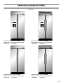
ESPECIFICACIONES DE DISEÑO
Modelos
Serie Masterpiece de acero inoxidable
Refrigerador de dos puertas con despachador
T42BD810NS T48BD810NS
Serie Professional de acero inoxidable
Refrigerador de dos puertas con despachador
T42BD820NS T48BD820NS
Serie Masterpiece de acero inoxidable
Refrigerador de dos puertas sin despachador
T42BR810NS T48BR810NS
Serie Professional de acero inoxidable
Refrigerador de dos puertas sin despachador
T42BR820NS T48BR820NS

20
REQUISITOS DE INSTALACIÓN
Herramientas y piezas
IMPORTANTE:
■ Instalador: Deje las Instrucciones de instalación con el
propietario.
■
Propietario: Conserve las Instrucciones de instalación para
referencia futura. Guarde estas Instrucciones de instalación
para tenerlas a disposición del inspector de electricidad local.
Herramientas necesarias
Reúna las herramientas y piezas necesarias antes de comenzar
la instalación. Lea y siga las instrucciones provistas con
cualquiera de las herramientas enlistadas aquí.
Piezas necesarias
■ Tornillos para madera #8 x 3" (7,6 cm) (pudieran necesitarse
más largos) (6)
■ Tableros de madera de 2" x 4" x 32" (5 cm x 10 cm x 81 cm)
(1
ó 2)
■
Si está conectando la línea de agua directamente a una tubería
de cobre y no a la válvula de cierre, necesitará una férula, una
unión y un accesorio de compresión de
¹⁄₄
" (6,35 mm).
Requisitos de ubicación
El refrigerador puede instalarse en un recinto entre los armarios o
al extremo de una línea de armarios utilizando un panel lateral
para cercar el refrigerador.
IMPORTANTE:
■ Observe todos los códigos y reglamentos aplicables.
■ No se recomienda instalar el refrigerador cerca de un horno,
radiador u otra fuente de calor.
■ No instale el refrigerador cerca de una ubicación en la que la
temperatura puede bajar de los 55°F (13°C).
■ El piso debe soportar el peso del refrigerador, más de
600 lbs (272 kg), los paneles de las puertas y el contenido del
refrigerador.
■ La altura del techo deberá permitir un arco de vuelco lateral.
Vea “Arco de vuelco”.
■ La ubicación debe permitir que la puerta abra totalmente.
Vea “Medidas de oscilación de las puertas”.
■ La ubicación debe permitir que se quite la rejilla superior.
Vea “Medidas de la abertura”.
Medidas de la abertura
■ Para evitar la inclinación durante el uso, el plafón sólido
deberá estar a 1" (2,5 cm) como máximo por encima del
refrigerador. Si el plafón sólido está a una altura de más de 1"
(2,5 cm) o no hay ninguno disponible, entonces el
refrigerador deberá tener un soporte.
Si se necesitan los tableros antivuelco, se deben ajustar en la
parte posterior de los pies derechos de la pared de 80" a 90"
(203 a 229 cm) arriba del piso. Vea “Cómo instalar los
tableros antivuelco” para obtener más información.
NOTA: Se debe mantener un espacio de ½" (1,3 cm) por
encima de la rejilla superior para poder quitarla.
■ Un contacto de tres terminales con conexión a tierra debe
estar ubicado dentro de una medida específica de los
armarios del lado derecho o del panel del extremo. Consulte
la tabla que sigue a la ilustración para ver la medida
necesaria para su modelo. Para obtener más información,
vea “Requisitos eléctricos”.
■ El cierre del agua deberá estar ubicado en la base del
armario, a cualquier lado del refrigerador o en algún otro
lugar de fácil acceso. Si la válvula de cierre del agua no está
en los armarios, la tubería para la línea del agua puede llegar
a través del piso o de la pared trasera. Vea “Requisitos del
suministro de agua” para obtener información adicional.
Juegos de manijas
Para usarse con modelos de acero inoxidable. Usted puede
comprar un tipo de manija diferente del que se provee con su
modelo. Consulte al distribuidor para más detalles.
PROHNDL160—Juego de manija Pro
PROHNDL165—Juego de manija Designer Pro
MASTHNDL55—Juego de manija Masterpiece
■ Taladro inalámbrico
■ Brocas
■ Llaves ajustables (2)
■ Destornillador Phillips
■ Nivel pequeño
■ Plataforma rodante para
electrodomésticos
■ Destornillador Torx
®†
T27
■ Llave para tuercas de ¹¹⁄₃₂"
■ Llaves de boca de ³⁄₈" y ¹⁄₂"
■ Llave hexagonal en L de ⁵⁄₃₂"
■ Llaves de cubo de ¹⁄₄" y ⁵⁄₁₆"
■ Cinta para medir
■ Cuchillo para uso general
†®TORX es una marca registrada de Saturn Fasteners, Inc.
ADVERTENCIA
Peligro de Explosión
Mantenga los materiales y vapores inflamables,
tales como gasolina, alejados del refrigerador.
No seguir esta instrucción puede ocasionar la muerte,
explosión, o incendio.
¹⁄₂
"
(1,3 cm)
La page charge ...
La page charge ...
La page charge ...
La page charge ...
La page charge ...
La page charge ...
La page charge ...
La page charge ...
La page charge ...
La page charge ...
La page charge ...
La page charge ...
La page charge ...
La page charge ...
La page charge ...
La page charge ...
La page charge ...
La page charge ...
La page charge ...
La page charge ...
La page charge ...
La page charge ...
La page charge ...
La page charge ...
La page charge ...
La page charge ...
La page charge ...
La page charge ...
-
 1
1
-
 2
2
-
 3
3
-
 4
4
-
 5
5
-
 6
6
-
 7
7
-
 8
8
-
 9
9
-
 10
10
-
 11
11
-
 12
12
-
 13
13
-
 14
14
-
 15
15
-
 16
16
-
 17
17
-
 18
18
-
 19
19
-
 20
20
-
 21
21
-
 22
22
-
 23
23
-
 24
24
-
 25
25
-
 26
26
-
 27
27
-
 28
28
-
 29
29
-
 30
30
-
 31
31
-
 32
32
-
 33
33
-
 34
34
-
 35
35
-
 36
36
-
 37
37
-
 38
38
-
 39
39
-
 40
40
-
 41
41
-
 42
42
-
 43
43
-
 44
44
-
 45
45
-
 46
46
-
 47
47
-
 48
48


