
11221320
Í?+6-4ÂÂ*ÂLÎ
1/2
Canada
Baumer Inc.
CA-Burlington, ON L7M 4B9
Phone +1 (1)905 335-8444
China
Baumer (China) Co., Ltd.
CN-201612 Shanghai
Phone +86 (0)21 6768 7095
Denmark
Baumer A/S
DK-8210 Aarhus V
Phone +45 (0)8931 7611
France
Baumer SAS
FR-74250 Fillinges
Phone +33 (0)450 392 466
Germany
Baumer GmbH
DE-61169 Friedberg
Phone +49 (0)6031 60 07 0
India
Baumer India Private Limited
IN-411038 Pune
Phone +91 20 2528 6833/34
Italy
Baumer Italia S.r.l.
IT-20090 Assago, MI
Phone +39 (0)2 45 70 60 65
Singapore
Baumer (Singapore) Pte. Ltd.
SG-339412 Singapore
Phone +65 6396 4131
Sweden
Baumer A/S
SE-56133 Huskvarna
Phone +46 (0)36 13 94 30
Switzerland
Baumer Electric AG
CH-8501 Frauenfeld
Phone +41 (0)52 728 1313
United Kingdom
Baumer Ltd.
GB-Watchfield, Swindon, SN6 8TZ
Phone +44 (0)1793 783 839
USA
Baumer Ltd.
US-Southington, CT 06489
Phone +1 (1)860 621-2121
www.baumer.com/worldwide
Baumer Electric AG · CH-8501 Frauenfeld
Phone +41 (0)52 728 1122 · Fax +41 (0)52 728 1144
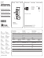
Radar Sensoren
Radar sensors
Détecteurs à radar
Radar Distanz messende Sensoren
Radar distance measuring sensors
Détecteurs de mesure de distances
Technische Daten Technical data Données techniques
Erfassungsbereich Sd 0,5 ... 60 m sensing distance Sd 0,5 ... 60 m Portée de détection Sd 0,5 ... 60 m
Temperaturdrift < ± 10 mm temperature drift < ± 10 mm Dérive en température < ± 10 mm
Betriebsspannungsbereich
+Vs
2)
12 ... 30 VDC voltage supply range
+Vs
2)
12 ... 30 VDC Plage de tension +Vs
2)
12 ... 30 VDC
Stromaufnahme max.
(ohne Last)
200 mA current consumption
max. (no load)
200 mA Consommation max. (sans
charge)
200 mA
Ausgangsstrom < 100mA (Ausgang 1)
< 50mA (Ausgang 2)
output current < 100mA (Output 1)
< 50mA (Output 2)
Courant de sortie < 100mA (Sortie 1)
< 50mA (Sortie 2)
Ausgangsschaltung Gegentakt / IO-Link output circuit push-pull / IO-Link Circuit de sortie push-pull / IO-Link
Kurzschlussfest ja short circuit protection yes Protégé contre courts-cir-
cuits
oui
Verpolungsfest ja, Vs zu GND reverse polarity pro-
tection
yes, Vs to GND Protégé contre inversion
polarité
oui, Vs vers GND
Arbeitstemperatur -40 ... +65 °C operating temperature -40 ... +65 °C Température de fonctionne-
ment
-40 ... +65 °C
Lagertemperatur -40 ... +85 °C storage temperature -40 ... +85 °C Température de stockage -40 ... +85 °C
Schutzart IP 68/69K & proTect+ protection class IP 68/69K & proTect+ Classe de protection IP 68/69K & proTect+
RR30.DAO0-11221320
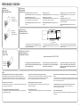
Abmessungen Dimensions Dimensions Elektrischer Anschluss Connection diagram Schéma de raccordement
• Alle Masse in mm
• All dimensions in mm
• Toutes les dimensions en mm
BN = Braun/brown/brun
BK = Schwarz/black/noi
r
WH = Weiss/white/blanc
BU = Blau/blue/bleu
GY = Grau/gray/gris
• Vor dem Anschliessen des Sensors die Anlage spannungsfrei schalten.
• Disconnect power before connecting the sensor.
• Mettre l`installation hors tension avant le raccordement du détecteur.
Class 2, UL 1310, siehe / see / voir au FAQ
2)
mit / with / avec IO-Link 18 ... 28VDC
50
17
ø 82
M30 x 1,5
M12 x 1
LED
ø 42
24
90
SW 36
0 V
+Vs
BU (3)
BN (1)
GY (5)
WH (2)
output 2
Z
Z
n.c.
output 1 / IO-Link
BK (4)
2 x
push pull
Z
Z
2
output 2
output 1/IO-Link
0V
4 1
3
+VS
5 n.c.

2/2
RR30.DAO0-11221320
Blinkmodi
Flashing modes
Modes de clignotement
Farben LED
Colors LED
Couleurs LED
Konfi guration über IO-Link
IO-Link confi guration
Confi guration via IO-Link
LED Anzeigen
LED indication
Indication LED
Erdungskonzept
Grounding concept
Concept mise à la terre
FAQ
• Wie empfi ndlich ist der Sensor auf ein Verkippen eines Objekts?
Die Empfi ndlichkeit gegen Verkippen eines Objekts ist abhängig von der
Objektgeometrie und der Position, an der ein Objekt erkannt werden soll. Ein
Verkippen kleiner als 3° toleriert der Sensor unter den meisten Bedingungen.
• Netzteil nach UL 1310, Class 2?
oder externe Absicherung durch eine UL anerkannte oder gelistete Sicherung mit
max. 30VAC/3A oder 24VDC/4A.
• Ist ein geschirmtes Anschlusskabel zu verwenden?
In Umgebungen mit starken elektromagnetischen Feldern wird ein geschirmtes
Anschlusskabel empfohlen.
• How sensitive is the sensor towards tilting of an object?
The sensitivity of tilting an object is dependent on the geometry of the object and
the position at which the object shall be detected. A tilt angle smaller
than 3° can be tolerated by the sensor in most of the cases.
• Voltage supply according UL 1310, Class2?
or device shall be protected by an external R/C or listed fuse, rated max.
30VAC/3A or 24VDC/4A.
• Is a shielded cable to use?
In environments with strong electromagnetic fi elds is recommended a shielded
cable with.
• Quel est le degré de sensibilité d‘un capteur en cas de renversement d‘un
objet ?
La sensibilité en cas de renversement d‘un objet dépend de sa géométrie et de la
position à laquelle un objet doit être détecté. Dans la plupart des cas, le capteur
tolère un basculement inférieur à 3°.
• L‘alimentation utilisée, couvre la classe 2 selon la norme UL 1310 ?
Ou appareil protégé en externe par un circuit R/C ou fusible UL à
30VAC/3A ou 24VDC/4A maximum.
• Est un câble blindé utiliser ?
Dans les environnements à fort champ électromagnétique est recommandé un
câble blindé.
In Umgebungen mit starken elektromagnetischen Fel-
dern wird ein geschirmtes Anschlusskabel mit obigem
Erdungskonzept empfohlen.
In environments with strong electromagnetic fi elds is
recommendeda shielded cable with grounding concept
as above.
Dans les environnements à fort champ électromagné-
tique est recommandé un câble blindé avec le concept
de mise à la terre.
Power-Supply
A/D Converter
Sensor
Potentialausgleichsleitung
Equipotential line
Ligne équipotentielle
Grün leuchtet: Betriebsspannung liegt an
Grün blinkt mit 1Hz: Kurzschluss am Schaltausgang
Gelb leuchtet: Ausgangsanzeige
Gelb blinkt mit 4 Hz: Stärke des empfangenen Sig-
nals ist grenzwertig, Ausgang unverändert
Beide LED blinken mit 4Hz: FindMe aktiviert (über
IO-Link)
Green is lit: power is on
Green fl ashes with 1Hz: short-circuit at voltage output
Yellow is lit: output indicatior
Yellow fl ashes with 4 Hz: Amplitude of signal is at the
lower limit, the output is not changed
Both LED fl ashes with 4Hz: FindMe activated (via
IO-Link)
Vert allumé: présence d’une alimentation électrique
Vert clignotant à 1Hz: court-circuit sur la sortie de
commutation
Jaune allumé: indicateur de sortie
Jaune clignotant à 4 Hz: l’intensité du signal reçu est
limite, sortie inchangée
Les deux LED clignotant à 4Hz: FindMe activé (via
IO-Link)
Gelb/Grün
Yellow/Green
Jaune/Vert
Blinken 1 Hz
Flashing 1 Hz
Clignotement 1 Hz
Blinken 4 Hz
Flashing 4 Hz
Clignotement 4 Hz
Die Anleitung für die Protokoll Struktur und die
Befehle sowie die dazu passende IODD sind online
als Download hinterlegt
The instructions for the protocol structure and
the commands as well as the matching IODD are
available online as downloads
Les instructions relatives à la structure du proto-
cole et aux commandes, ainsi que l’IODD corres-
pondant, sont disponibles en ligne sous forme de
téléchargements.
https://www.baumer.com/PID/11221320
-
 1
1
-
 2
2


dans d''autres langues
Documents connexes
-
Baumer RR30.DAO0-IGPI.9VF Mode d'emploi
-
Baumer RR30.DAF0-GGPI.9VF/E029 Mode d'emploi
-
-
-
Baumer RR30 Mode d'emploi
-
-
-
-
-