Hikoki DH 40FR Manuel utilisateur
- Catégorie
- Outils électroportatifs
- Taper
- Manuel utilisateur
Ce manuel convient également à

DOUBLE INSULATION
DOUBLE ISOLATION
AISLAMIENTO DOBLE
INSTRUCTIONS DE SECURITE ET MODE D’EMPLOI
AVERTISSEMENT
Une utilisation INCORRECTE OU DANGEREUSE de cet outil motorisé peut entraîner la
mort ou de sérieuses blessures corporelles!
Ce mode d’emploi contient d’importantes informations à propos de la sécurité de ce
produit. Prière de lire et de comprendre ce mode d’emploi AVANT d’utiliser l’outil
motorisé. Garder ce mode d’emploi à la disponibilité des autres utilisateurs et propriétaires
avant qu’ils utilisent l’outil motorisé. Ce mode d’emploi doit être conservé dans un
endroit sûr.
SAFETY INSTRUCTIONS AND INSTRUCTION MANUAL
WARNING
IMPROPER OR UNSAFE use of this power tool can result in death or serious bodily
injury!
This manual contains important information about product safety. Please read and
understand this manual BEFORE operating the power tool. Please keep this manual
available for other users and owners before they use the power tool. This manual should
be stored in safe place.
INSTRUCCIONES DE SEGURIDAD Y MANUAL DE INSTRUCCIONES
ADVERTENCIA
¡La utilización INAPROPIADA O PELIGROSA de esta herramienta eléctrica puede
resultar en lesiones de gravedad o la muerte!
Este manual contiene información importante sobre la seguridad del producto. Lea y
comprenda este manual ANTES de utilizar la herramienta eléctrica. Guarde este manual
para que puedan leerlo otras personas antes de utilizar la herramienta eléctrica. Este
manual debe ser guardado en un lugar seguro.
Model Rotary Hammer
Modèle Marteau rotatif
Modelo Martillo perforador
DH 40FR
01Eng_DH40FR_US 5/25/12, 8:431

IMPORTANT SAFETY INFORMATION ................ 3
MEANINGS OF SIGNAL WORDS ........................ 3
SAFETY ...................................................................... 3
GENERAL POWER TOOL SAFETY WARNINGS .......
3
SPECIFIC SAFETY RULES AND SYMBOLS ......... 4
DOUBLE INSULATION FOR SAFER
OPERATION ................................................... 5
FUNCTIONAL DESCRIPTION .................................... 7
NAME OF PARTS .................................................. 7
SPECIFICATIONS .................................................. 7
ASSEMBLY AND OPERATION ................................. 8
APPLICATIONS ..................................................... 8
PRIOR TO OPERATION ......................................... 8
HOW TO USE ...................................................... 10
HOW TO USE THE CORE BIT ............................. 12
MAINTENANCE AND INSPECTION ....................... 14
ACCESSORIES ......................................................... 16
STANDARD ACCESSORIES ............................... 16
OPTIONAL ACCESSORIES ................................. 16
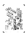
PARTS LIST .............................................................. 52
CONTENTS
English
Page Page
INFORMATIONS IMPORTANTES DE
SÉCURITÉ ..................................................... 19
SIGNIFICATION DES MOTS
D’AVERTISSEMENT .................................... 19
SECURITE ................................................................ 19
AVERTISSEMENTS DE SÉCURITÉ GÉNÉRAUX
CONCERNANT LES OUTILS ÉLECTRIQUES ......
19
REGLES DE SECURITE SPECIFIQUES ET
SYMBOLES .................................................. 21
DOUBLE ISOLATION POUR UN
FONCTIONNEMENT PLUS SUR ................. 22
DESCRIPTION FONCTIONNELLE ........................... 23
NOM DES PARTIES ............................................ 23
SPECIFICATIONS ................................................ 23
ASSEMBLAGE ET FONCTIONNEMENT ................ 24
APPLICATIONS ................................................... 24
AVANT L’UTILISATION ...................................... 24
UTILISATION ....................................................... 26
COMMENT UTILISER LA COURONNE .............. 28
ENTRETIEN ET INSPECTION .................................. 30
ACCESSOIRES ......................................................... 32
ACCESSOIRES STANDARD ............................... 32
ACCESSOIRES SUR OPTION ............................. 32
LISTA DES PIÈCES .................................................. 52
TABLE DES MATIERES
Français
Page Page
INFORMACIÓN IMPORTANTE SOBRE
SEGURIDAD ................................................. 35
SIGNIFICADO DE LAS PALABRAS DE
SEÑALIZACIÓN ............................................ 35
SEGURIDAD ............................................................. 35
ADVERTENCIAS DE SEGURIDAD GENERAL
DE LA HERRAMIENTA ELÉCTRICA ............ 35
NORMAS Y SÍMBOLOS ESPECÍFICOS DE
SEGURIDAD ................................................. 37
AISLAMIENTO DOBLE PARA OFRECER
UNA OPERACIÓN MÁS SEGURA .............. 38
DESCRIPCIÓN FUNCIONAL .................................... 39
NOMENCLATURA ............................................... 39
ESPECIFICACIONES ............................................ 39
MONTAJE Y OPERACIÓN ...................................... 40
APLICACIONES ................................................... 40
ANTES DE LA OPERACIÓN ................................ 40
MODO DE UTILIZACIÓN .................................... 42
MODO DE USAR LA BARRENA TUBULAR ....... 45
MANTENIMIENTO E INSPECCIÓN ........................ 47
ACCESORIOS ........................................................... 49
ACCESORIOS ESTÁNDAR ................................. 49
ACCESORIOS OPCIONALES .............................. 49
LISTA DE PIEZAS .................................................... 52
ÍNDICE
Español
Página Página
01Eng_DH40FR_US 5/25/12, 8:432

English
3
IMPORTANT SAFETY INFORMATION
Read and understand all of the safety precautions, warnings and operating instructions in the Instruction Manual
before operating or maintaining this power tool.
Most accidents that result from power tool operation and maintenance are caused by the failure to observe basic
safety rules or precautions. An accident can often be avoided by recognizing a potentially hazardous situation
before it occurs, and by observing appropriate safety procedures.
Basic safety precautions are outlined in the “SAFETY” section of this Instruction Manual and in the sections which
contain the operation and maintenance instructions.
Hazards that must be avoided to prevent bodily injury or machine damage are identified by WARNINGS on the
power tool and in this Instruction Manual.
NEVER use this power tool in a manner that has not been specifically recommended by HITACHI.
MEANINGS OF SIGNAL WORDS
WARNING indicates a potentially hazardous situations which, if ignored, could result in death or serious injury.
CAUTION indicates a potentially hazardous situations which, if not avoided, may result in minor or moderate
injury, or may cause machine damage.
NOTE emphasizes essential information.
SAFETY
GENERAL POWER TOOL SAFETY WARNINGS
WARNING:
Read all safety warnings and all instructions.
Failure to follow the warnings and instructions may result in electric shock, fire and/or serious injury.
Save all warnings and instructions for future reference.
The term “power tool” in the warnings refers to your mains-operated (corded) power tool or battery-operated
(cordless) power tool.
1) Work area safety
a) Keep work area clean and well lit.
Cluttered or dark areas invite accidents.
b) Do not operate power tools in explosive
atmospheres, such as in the presence of
flammable liquids, gases or dust.
Power tools create sparks which may ignite
the dust or fumes.
c) Keep children and bystanders away while
operating a power tool.
Distractions can cause you to lose control.
2) Electrical safety
a) Power tool plugs must match the outlet.
Never modify the plug in any way.
Do not use any adapter plugs with earthed
(grounded) power tools.
Unmodified plugs and matching outlets will
reduce risk of electric shock.
b) Avoid body contact with earthed or grounded
surfaces such as pipes, radiators, ranges and
refrigerators.
There is an increased risk of electric shock if
your body is earthed or grounded.
c) Do not expose power tools to rain or wet
conditions.
Water entering a power tool will increase the
risk of electric shock.
d) Do not abuse the cord. Never use the cord for
carrying, pulling or unplugging the power tool.
Keep cord away from heat, oil, sharp edges
or moving parts.
Damaged or entangled cords increase the risk
of electric shock.
e) When operating a power tool outdoors, use
an extension cord suitable for outdoor use.
Use of a cord suitable for outdoor use reduces
the risk of electric shock.
f) If operating a power tool in a damp location
is unavoidable, use a residual current device
(RCD) protected supply.
Use of an RCD reduces the risk of electric shock.
3) Personal safety
a) Stay alert, watch what you are doing and use
common sense when operating a power tool.
Do not use a power tool while you are tired
or under the influence of drugs, alcohol or
medication.
01Eng_DH40FR_US 5/25/12, 8:433

English
4
A moment of inattention while operating power
tools may result in serious personal injury.
b) Use personal protective equipment. Always
wear eye protection.
Protective equipment such as dust mask, non-
skid safety shoes, hard hat, or hearing
protection used for appropriate conditions
will reduce personal injuries.
c) Prevent unintentional starting. Ensure the
switch is in the off-position before connecting
to power source and/or battery pack, picking
up or carrying the tool.
Carrying power tools with your finger on the
switch or energising power tools that have
the switch on invites accidents.
d) Remove any adjusting key or wrench before
turning the power tool on.
A wrench or a key left attached to a rotating part
of the power tool may result in personal injury.
e) Do not overreach. Keep proper footing and
balance at all times.
This enables better control of the power tool
in unexpected situations.
f) Dress properly. Do not wear loose clothing
or jewellery. Keep your hair, clothing and
gloves away from moving parts.
Loose clothes, jewellery or long hair can be
caught in moving parts.
g) If devices are provided for the connection of
dust extraction and collection facilities, ensure
these are connected and properly used.
Use of dust collection can reduce dust-related
hazards.
4) Power tool use and care
a) Do not force the power tool. Use the correct
power tool for your application.
The correct power tool will do the job better
and safer at the rate for which it was designed.
b) Do not use the power tool if the switch does
not turn it on and off.
Any power tool that cannot be controlled with
the switch is dangerous and must be repaired.
c) Disconnect the plug from the power source
and/or the battery pack from the power tool
before making any adjustments, changing
accessories, or storing power tools.
Such preventive safety measures reduce the
risk of starting the power tool accidentally.
d) Store idle power tools out of the reach of
children and do not allow persons unfamiliar
with the power tool or these instructions to
operate the power tool.
Power tools are dangerous in the hands of
untrained users.
e) Maintain power tools. Check for
misalignment or binding of moving parts,
breakage of parts and any other condition
that may affect the power tool’s operation.
If damaged, have the power tool repaired
before use.
Many accidents are caused by poorly
maintained power tools.
f) Keep cutting tools sharp and clean.
Properly maintained cutting tools with sharp
cutting edges are less likely to bind and are
easier to control.
g) Use the power tool, accessories and tool bits
etc. in accordance with these instructions,
taking into account the working conditions
and the work to be performed.
Use of the power tool for operations different
from those intended could result in a
hazardous situation.
5) Service
a) Have your power tool serviced by a qualified
repair person using only identical
replacement parts.
This will ensure that the safety of the power
tool is maintained.
SPECIFIC SAFETY RULES AND SYMBOLS
1. Wear ear protectors.
Exposure to noise can cause hearing
loss.
2. Use auxiliary handles, if supplied with the tool.
Loss of control can cause personal injury.
3. Hold power tools by insulated gripping surfaces
when performing an operation where the cutting
tool may contact hidden wiring or its own cord.
Cutting accessory contacting a “live” wire may
make exposed metal parts of the power tool “live”
and could give the operator an electric shock.
4. NEVER touch the tool bit with bare hands after
operation.
5. NEVER wear gloves made from materials likely to
roll up such as cotton, wool, cloth or string, etc.
6. ALWAYS attach the side handle and securely grip
the Demolition Hammer.
7. NEVER touch moving parts.
NEVER place your hands, fingers or other body
parts near the tool’s moving parts.
8. NEVER operate without all guards in place.
NEVER operate this tool without all guards or
safety features in place and in proper working
order. If maintenance or servicing requires the
removal of a guard or safety feature, be sure to
replace the guard or safety feature before resuming
operation of the tool.
9. Use right tool.
Don’t force small tool or attachment to do the job
of a heavy-duty tool.
01Eng_DH40FR_US 5/25/12, 8:434

English
5
Don’t use tool for purpose not intended —for
example— don’t use circular saw for cutting tree
limbs or logs.
10. NEVER use a power tool for applications other
than those specified.
NEVER use a power tool for applications other than
those specified in the Instruction Manual.
11. Handle tool correctly.
Operate the tool according to the instructions
provided herein. Do not drop or throw the tool.
NEVER allow the tool to be operated by children,
individuals unfamiliar with its operation or
unauthorized personnel.
12. Keep all screws, bolts and covers tightly in place.
Keep all screws, bolts, and plates tightly mounted.
Check their condition periodically.
13. Do not use power tools if the plastic housing or
handle is cracked.
Cracks in the tool’s housing or handle can lead to
electric shock. Such tools should not be used until
repaired.
14. Blades and accessories must be securely mounted
to the tool.
Prevent potential injuries to yourself or others.
Blades, cutting implements and accessories which
have been mounted to the tool should be secure
and tight.
15. Keep motor air vent clean.
The tool’s motor air vent must be kept clean so
that air can freely flow at all times. Check for dust
build-up frequently.
16. Operate power tools at the rated voltage.
Operate the power tool at voltages specified on its
nameplate.
If using the power tool at a higher voltage than
the rated voltage, it will result in abnormally fast
motor revolution and may damage the unit and
the motor may burn out.
17. NEVER use a tool which is defective or operating
abnormally.
If the tool appears to be operating unusually,
making strange noises, or otherwise appears
defective, stop using it immediately and arrange
for repairs by a Hitachi authorized service center.
18. NEVER leave tool running unattended. Turn power
off.
Don’t leave tool until it comes to a complete stop.
19. Carefully handle power tools.
Should a power tool be dropped or struck against
hard materials inadvertently, it may be deformed,
cracked, or damaged.
20. Do not wipe plastic parts with solvent.
Solvents such as gasoline, thinner benzine, carbon
tetrachloride, and alcohol may damage and crack
plastic parts. Do not wipe them with such solvents.
Wipe plastic parts with a soft cloth lightly
dampened with soapy water and dry thoroughly.
21. ALWAYS wear eye protection that meets the
requirement of the latest revision of
ANSI Standard Z87.1.
22. ALWAYS be careful with buried object such as an
underground wiring.
Touching live wiring or electric cable with this tool
may result in electric shock.
Confirm before use whether hidden objects are
present, such as electric cables within the wall,
floor or ceiling.
23. Definitions for symbols used on this tool
V ............... volts
Hz ............. hertz
A ............... amperes
n
o .............. no load speed
W .............. watt
............. Class II Construction
---/min ...... revolutions per minute
.............. Alternating current
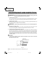
DOUBLE INSULATION FOR SAFER
OPERATION
To ensure safer operation of this power tool, HITACHI
has adopted a double insulation design. “Double
insulation” means that two physically separated
insulation systems have been used to insulate the
electrically conductive materials connected to the power
supply from the outer frame handled by the operator.
Therefore, either the symbol “ ” or the words “Double
insulation” appear on the power tool or on the
nameplate.
Although this system has no external grounding, you
must still follow the normal electrical safety precautions
given in this Instruction Manual, including not using
the power tool in wet environments.
To keep the double insulation system effective, follow
these precautions:
䡬
Only HITACHI AUTHORIZED SERVICE CENTER
should disassemble or assemble this power tool,
and only genuine HITACHI replacement parts
should be installed.
䡬
Clean the exterior of the power tool only with a
soft cloth moistened with soapy water, and dry
thoroughly.
Never use solvents, gasoline or thinners on plastic
components; otherwise the plastic may dissolve.
01Eng_DH40FR_US 7/26/12, 11:385

English
6
SAVE THESE INSTRUCTIONS
AND
MAKE THEM AVAILABLE TO OTHER USERS
AND
OWNERS OF THIS TOOL!
01Eng_DH40FR_US 5/25/12, 8:436

English
7
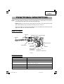
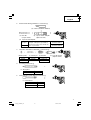
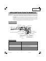
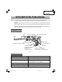
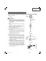
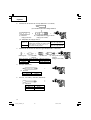
Fig. 1
Housing
Stopper
Tool Holder
Switch Trigger
Side Handle
Handle
Nameplate
Tail Cover
Set Screw
(Under the
Tail Cover)
Selector Lever
Brush Cap
(Inside the Tail Cover)
Dial
Motor Single-Phase, Series Commutator Motor.
Power Source Single-Phase, 120 V 60 Hz
Current 9.2 A
Capacity Drill Bit: 1-9/16" (40 mm)
Core Bit: 4-1/8" (105 mm)
No-Load Speed 240 – 480/min
Full-load Blow 1320 – 2650/min
Weight 14.3 lbs (6.5 kg)
Drill Bit
FUNCTIONAL DESCRIPTION
NOTE: The information contained in this Instruction Manual is designed to assist you in
the safe operation and maintenance of the power tool.
NEVER operate, or attempt any maintenance on the tool unless you have first read
and understood all safey instructions contained in this manual.
Some illustrations in this Instruction Manual may show details or attachments that
differ from those on your own power tool.
NAME OF PARTS
SPECIFICATIONS
01Eng_DH40FR_US 5/25/12, 8:437

English
8
ASSEMBLY AND OPERATION
APPLICATIONS
Rotation and hammering function
䡬 Drilling anchor holes
䡬 Drilling holes in concrete
Hammering function only
䡬 Crushing concrete, chipping, digging, and squaring
(by applying optional accessories)
PRIOR TO OPERATION
1. Power source
Ensure that the power source to be utilized conforms to the power source requirements
specified on the product nameplate.
2. Power switch
Ensure that the switch is in the OFF position. If the plug is connected to a receptacle
while the switch is in the ON position, the power tool will start operating immediately
and can cause serious injury.
3. Extension cord
When the work area is far away from the power source, use an extension cord of
sufficient thickness and rated capacity. The extension cord should be kept as short as
practicable.
WARNING:
Damaged cord must be replaced or repaired.
4. Check the receptacle
If the receptacle only loosely accepts the plug, the receptacle must be repaired. Contact
a licensed electrician to make appropriate repairs.
If such a faulty receptacle is used, it may cause overheating, resulting in a serious
hazard.
5. Confirming condition of the environment:
Confirm that the work site is placed under appropriate conditions conforming to
prescribed precautions.
01Eng_DH40FR_US 7/26/12, 11:388

English
9
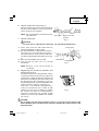
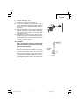
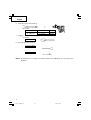
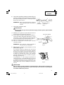
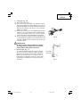
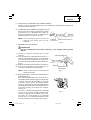
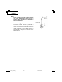
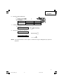
6. How to install dust cover (Fig. 2)
Always install the dust cover on the drill bit or
the taper shank adaptor. Insert the dust cover
until it lies flush in the groove.
NOTE: For a thick drill bit, insert the dust cover
from drill rear.
7. How to install tool
CAUTION:
For tools such as a drill bit and a bull point, use only Hitachi genuine parts.
(1) Clean, then smear the tool shank with the
grease provided in the green tube.
(2) Pull the tool holder in the direction of arrow 1
and rotate it in the direction of arrow 2
(counterclockwise). Fully insert the tool shank
into the hexagonal hole of the front cover. (Fig.
3)
(3) Return the tool holder to fix the tool.
(4) Pull the tool to make sure it is locked
completely.
NOTE: Remove in the reverse order to
installation.
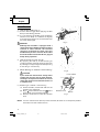
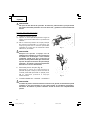
8. Regulating the number of rotations and
hammering (Fig. 4)
This Rotary Hammer is equipped with a built-
in electronic control circuit that can adjust and
regulate the number of rotations and times of
hammering. This Rotary Hammer can be used
by adjusting the dial, depending upon the
contents of operation, such as boring holes into
fragile materials, chipping, centering, etc.
The scale ‘1’ of the dial is designed for a
minimum speed with the number of 240
rotations per minute and 1320 times of blow
per minute. The scale ‘6’ is designed for a
maximum speed with the number of 480
rotations per minute and 2650 times of blow
per minute.
CAUTION:
Do not adjust the dial during operation. Doing so can result in injury because the
Rotary Hammer must be held by only one hand, disabling the steady control of the
Rotary Hammer.
Fig. 3
Tool Holder
Tool Shank
Dial
Fig. 4
Fig. 2
Dust cover
Insert up to the
groove
Front Cover
1
2
01Eng_DH40FR_US 5/25/12, 8:439

English
10
Fig. 6
Fig. 5
Fig. 7
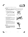
Selector Lever
Lever Holder
Button
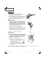
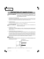
HOW TO USE
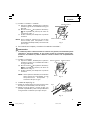
1. How to drill holes (Fig. 5)
(1) Pull the switch trigger after applying the drill
bit tip to the drilling position.
(2) It is unnecessary to forcibly press the Rotary
Hammer main body. It is sufficient to slightly
press the rotary hammer to an extent that clips
are freely discharged.
CAUTION:
Although this machine is equipped with a
safety clutch, if the drill bit becomes bound in
concrete or other material, the resultant
stoppage of the drill bit could cause the
machine body to turn in reaction. Ensure that
the main handle and side handle are gripped
firmly during operation.
2. How to chisel or crush (Fig. 6)
By applying the tool tip to the chiseling or
crushing position, operate the rotary hammer
by utilizing its empty weight. Forcible pressing
or thrusting is unnecessary.
3. When drilling at “rotation + hammering”
CAUTION:
If you switch the selector lever during motor
rotation, the tool can start to rotate abruptly,
resulting in unexpected accidents. Be sure to
switch the selector lever when the motor is at
a complete stop.
(1) Switching to “rotation + hammering”
(a) Push the button, release lock and turn the
selector lever clockwise.
(b) Align
of the selector lever and of the
lever holder as illustrated in Fig. 7.
(c) Release the button to lock the selector
lever.
NOTE: Turn the selector lever (do not push the button) to check if it is completely locked
and make sure that it does not turn.
01Eng_DH40FR_US 5/25/12, 8:4310

English
11
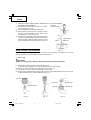
Lever HolderSelector Lever
Fig. 8
Stopper
Side Handle
Fig. 9
Button
Fig. 10
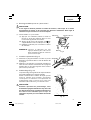
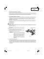
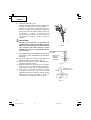
4. When chipping and shredding at “hammering”:
CAUTION:
䡬 If the selector lever is switched during motor rotation, the tool can start to rotate
abruptly, resulting in unexpected accidents. Make sure to switch the selector lever
when the motor is at a complete stop.
(1) Switching to “hammering”
(a) Push the button, release lock and turn the
selector lever counterclockwise.
(b) Align
of the selector lever and of the
lever holder as illustrated in Fig. 8.
(c) Release the button to lock the selector
lever.
NOTE: Turn the selector lever (do not push
the button) to check if it is completely
locked and make sure that it does not
turn.
5. Install the stopper (Fig. 9)
(1) Loosen the side handle and insert the straight
portion of the stopper into the handle bolt hole
from the front cover.
(2) Loosen the side handle, move the stopper to
the specified position and rotate the grip of the
side handle clockwise to fix the stopper.
6. Warming up (Fig. 10)
The grease lubrication system in this unit may
require warming up in cold regions.
Position the end of the bit so makes contact
with the concrete, turn on the switch and
perform the warming up operation. Make sure
that a hitting sound is produced and then use
the unit.
CAUTION:
When the warming up operation is performed,
hold the side handle and the main body
securely with both hands to maintain a secure
grip and be careful not to twist your body by
the jammed drill bit.
01Eng_DH40FR_US 5/25/12, 8:4311

English
12
Fig. 11
Drill Bit
(Taper shank)
Taper Shank Adaptor
Fig. 14
Taper Shank
Adaptor
Cotter
Support
Fig. 12
Fig. 15
Center Pin
Core Bit
Core Bit Tip
Guide Plate
Fig. 13
Core Bit
Core Bit Shank
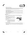
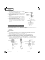
7. How to use the drill bit (taper shank) and
the taper shank adaptor.
(1) Install drill bit with taper shank in the taper
shank adaptor. (Fig. 11)
(2) Turn the power on and drill a base hole.
(3) After cleaning out dust with a syringe, attach
the plug to the anchor tip and drive in the
anchor with a manual hammer.
(4) To remove the drill bit with taper shank, insert
a cotter into the slot of the taper shank adaptor,
place supports under the Rotary Hammer and
tap the cotter with a manual hammer. (Fig. 12)
HOW TO USE THE CORE BIT
When boring penetrating large hole use the core bit. At that time use with the center pin
and the core bit shank provided as optional accessories.
1. Mounting
CAUTION:
Be sure to turn power OFF and disconnect the plug from the receptacle.
(1) Mount the core bit to the core bit shank. (Fig. 13)
Lubricate the thread of the core bit shank to facilitate disassembly.
(2) Mount the core bit shank to the Rotary Hammer. (Fig. 14)
(3) Insert the center pin into the guide plate until it stops.
(4) Engage the guide plate with the core bit, and turn the guide plate to left or right so that
it does not fall even if it faces downward. (Fig. 15)
01Eng_DH40FR_US 5/25/12, 8:4312

English
13
Fig. 16
Core Bit
Shank
Fig. 17
2. How to bore (Fig. 16)
(1) Connect the plug to the receptacle.
(2) A spring is installed in the center pin. Push it
lightly to the wall or the floor straight. Connect
all over the surface of the core bit tip and start
operating.
(3) When boring about 3/16" (5 mm) in depth the
position of the hole will establish. Bore after
that removing the center pin and the guide
plate from core bit.
(4) Application of excessive force will not only
expedite the work, but will deteriorate the tip
edge of the drill bit, resulting in reduced service
life of the rotary hammer.
CAUTION:
When removing the center pin and the guide
plate, turn OFF the switch and disconnect the
plug from the receptacle.
3. Dismounting (Fig. 17)
Remove the core bit shank from the rotary
hammer and strike the head of the core bit
shank strongly two or three times with a
manual hammer holding the core bit, then the
thread becomes loose and the core bit can be
removed.
01Eng_DH40FR_US 5/25/12, 8:4313

English
14
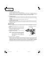
Wear limit
No. of carbon brush
0.28" (7 mm)
0.67" (17 mm)
73
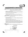
MAINTENANCE AND INSPECTION
WARNING: Be sure to switch power OFF and disconnect the plug from the
receptacle during maintenance and inspection.
1. Inspecting the drill bits
Since use of a dull tool will cause motor malfunctioning and degraded efficiency, replace
the drill bit with a new one or resharpening without delay when abrasion is noted.
2. Inspecting the screws
Regularly inspect all screws and ensure that they are properly tightened. Should any of
the screws be loose, retighten them immediately.
WARNING: Using this Rotary Hammer with loosen screws is extremely dangerous.
3. Maintenance of the motor
The motor unit winding is the very “heart” of the power tool. Exercise due care to
ensure the winding does not become damaged and/or wet with oil or water.
4. Inspecting the carbon brushes: (Fig. 18)
The motor employs carbon brushes which are consumable parts. When they become
worn to or near “wear limit”, it could result in motor trouble. When an auto-stop carbon
brush is equipped, the motor will stop automatically. At that time, replace both carbon
brushes with new ones which have the same carbon brush Nos. shown in the figure.
In addition, always keep carbon brushes clean and ensure that they slide freely within
the brush holders.
CAUTION:
Using this Rotary Hammer with a carbon brush which is worn in excess of the wear
limit will damage the motor.
Fig. 18
NOTE: Use HITACHI carbon brush No.73 indicated in Fig. 18
01Eng_DH40FR_US 5/25/12, 8:4314

English
15
Crank Cover
Fig. 19
䡬 Replacing carbon brushes:
(For parts name, refer to Fig. 1)
Loosen the two set screws and remove the tail cover. Remove the brush caps and
carbon brushes. After replacing the carbon brushes, tighten the brush caps securely
and to install the tail cover with securely tightening two set screws.
5. How to replase grease
This machine is full air-tight construction to protect against dust and to prevent lubricant
leakage. Therefore, the machine can be used without lubrication for long periods.
Replace the grease as described below.
䡬 Grease replacement period
After purchase, replace grease after every 6 months of usage. Ask for grease replacement
at the nearest HITACHI Authorized Service Center. Proceed for replacement of grease.
䡬 Grease replenishment
CAUTION:
Before replenishing the grease, turn the power off and pull out the power plug.
(1) Remove the crank cover and wipe off the
grease inside.
(2) Apply 1.0 oz (30 g) of HITACHI Electric Hammer
Grease A (standard accessory, contained in
tube) to the crank case.
(3) After replenishing the grease, install the crank
cover securely.
NOTE: The HITACHI Electric Hammer Grease
A is of the lower viscosity type. When
the supplied grease tube is consumed,
purchase from a HITACHI Autorized
Service Center.
6. Service and repairs
All quality power tools will eventually require servicing or replacement of parts because
of wear from normal use. To assure that only authorized replacement parts will be
used, all service and repairs must be performed by a HITACHI AUTHORIZED SERVICE
CENTER, ONLY.
01Eng_DH40FR_US 5/25/12, 8:4315

English
16
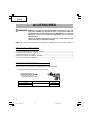
Overall length
16"(400 mm)
Code No.
985375
985376
External dia.
1" (25 mm)
1-1/2" (38 mm)
(1) Drill bit (Spline shank)
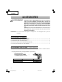
ACCESSORIES
WARNING: ALWAYS use Only authorized HITACHI replacement parts and
accessories. NEVER use replacement parts or accessories which are
not intended for use with this tool. Contact HITACHI if you are not sure
whether it is safe to use a particular replacement part or accessory
with your tool.
The use of any other attachment or accessory can be dangerous and
could cause injury or mechanical damage.
NOTE: Accessories are subject to change without any obligation on the part of the HITACHI.
STANDARD ACCESSORIES
(1) Case (Molded plastic) (Code No. 322152).......................................................................... 1
(2) Side Handle (Code No. 313078).......................................................................................... 1
(3) Stopper (Code No. 971786)................................................................................................. 1
(4) Hammer Grease A (Code No. 981840) ............................................................................... 1
(5) Dust Cover (Code No. 993245) ........................................................................................... 1
OPTIONAL ACCESSORIES.....sold separately
For accessories in detail please call HITACHI AT 1-800-59-TOOLS
1. Through-hole drilling (Rotation + Hammering)
01Eng_DH40FR_US 5/25/12, 8:4316

English
17
2. Anchor hole drilling (Rotation + Hammering)
(2) Taper shank adaptor
3. Large-dia. hole boring (Rotation + Hammering)
4. Crushing (Hammering)
5. Groove digging and edging (Hammering)
Taper shank adaptor formed
A-taper or B-taper is provided as
optional accessory, but drill bit for
it is not provided
Code No. 985377
Code No. 985378
A-taper
B-taper
(1) Drill bit
(Taper shank)
(3) Cotter (Code No. 944477)
(2) Taper shank adaptor
(Spline shank)
(Guide plate)
Code No.
985388
955169
(2) Core bit
External dia.
2" (50 mm)
4-1/8" (105 mm)
(1) Center pin
Code No.
955165
(3) Core bit shank
(Spline shank)
(1) Cold chisel
Overall length Code No.
12" (300 mm) 985381
18" (460 mm) 985382
(1) Bull point
Overall length Code No.
12" (300 mm) 985383
01Eng_DH40FR_US 5/25/12, 8:4317

English
18
(1) Cutter
Overall length Width Code No.
12" (300 mm)
1-1/2" (38 mm) 985384
2" (50 mm) 985385
(1) Scoop
Code No. 985386
6. Asphalt cutting (Hammering)
7. Digging
8. Syringe (for chip removal)
NOTE: Specifications are subject to change without any obligation on the part of the
HITACHI.
Code No. 985386
Code No. 320859
Code No. 318085
01Eng_DH40FR_US 5/25/12, 8:4318

Français
19
INFORMATIONS IMPORTANTES DE SÉCURITÉ
Lire et comprendre toutes les précautions de sécurité, les avertissements et les instructions de fonctionnement
dans ce mode d’emploi avant d’utiliser ou d’entretenir cet outil motorisé.
La plupart des accidents causés lors de l’utilisation ou de l’entretien de l’outil motorisé proviennent d’un non
respect des règles ou précautions de base de sécurité. Un accident peut la plupart du temps être évité si l’on
reconnaît une situation de danger potentiel avant qu’elle ne se produise, et en observant les procédures de sécurité
appropriées.
Les précautions de base de sécurité sont mises en évidence dans la section “SECURITE” de ce mode d’emploi et
dans les sections qui contiennent les instructions de fonctionnement et d’entretien.
Les dangers qui doivent être évités pour prévenir des blessures corporelles ou un endommagement de la machine
sont identifiés par AVERTISSEMENTS sur l’outil motorisé et dans ce mode d’emploi.
NE JAMAIS utiliser cet outil motorisé d’une manière qui n’est pas spécifiquement recommandée par HITACHI.
SIGNIFICATION DES MOTS D’AVERTISSEMENT
AVERTISSEMENT indique des situations potentiellement dangereuses qui, si elles sont ignorées, pourraient
entraîner la mort ou de sérieuses blessures.
PRECAUTION indique des situations dangereuses potentilles qui, si elles ne sont pas évitées, peuvent entraîner
de mineures et légères blessures ou endommager la machine.
REMARQUE met en relief des informations essentielles.
SECURITE
AVERTISSEMENTS DE SÉCURITÉ GÉNÉRAUX CONCERNANT LES OUTILS ÉLECTRIQUES
AVERTISSEMENT :
Lire tous les avertissements de sécurité et toutes les instructions
Tout manquement à observer ces avertissements et instructions peut engendrer des chocs électriques, des
incendies et/ou des blessures graves.
Conservez tous les avertissements et toutes les instructions pour vous y référer ultérieurement.
Le terme "outil électrique", utilisé dans les avertissements, se réfère aux outils électriques (câblé) ou aux
outils à piles (sans fil).
1) Sécurité de l’aire de travail
a) Maintenir l'aire de travail propre et bien
éclairée.
Les endroits encombrés ou sombres sont
propices aux accidents.
b) Ne pas utiliser d'outils électriques en présence
de liquides, gaz ou poussière inflammables,
au risque de provoquer une explosion.
Les outils électriques créent des étincelles
susceptibles d'enflammer la poussière.
c) Ne pas laisser les enfants et les visiteurs
s'approcher de vous lorsque vous utiliser un
outil électrique.
Les distractions peuvent faire perdre le contrôle.
2) Sécurité électrique
a) Les prises de l'outil électrique doivent
correspondre à la prise secteur.
Ne jamais modifier la prise.
Ne pas utiliser d'adaptateurs avec les outils
électriques mis à la masse.
Les prises non modifiées et les prises secteurs
correspondantes réduisent les risques de
choc électrique.
b) Eviter tout contact avec les surfaces mises à
la masse telles que les tuyaux, radiateurs,
bandes et réfrigérateurs.
Le risque de choc électrique est accru en cas
de mise à la masse du corps.
c) Ne pas exposer les outils électriques à la pluie
ou à des conditions humides.
Si l'eau pénètre dans l'outil, cela augmente
les risques de choc électrique.
d) Ne pas utiliser le cordon à tort. Ne jamais
utiliser le cordon pour transporter ou
débrancher l'outil électrique.
Maintenir le cordon loin de la chaleur, de
l'huile, des bords pointus ou des pièces
mobiles.
Les cordons endommagés ou usés
augmentent les risques de choc électrique.
02Fre_DH40FR_US 5/25/12, 8:4419

Français
20
e) En cas d'utilisation d'un outil électrique à
l'extérieur, utiliser un cordon de rallonge
adapté à un usage extérieur.
L'utilisation d'un cordon adapté à l'usage
extérieur réduit les risques de choc électrique.
f) Si vous devez utiliser un outil électrique dans
un endroit humide, utilisez une alimentation
protégée contre les courants résiduels.
L'utilisation d'un dispositif de protection
contre les courants résiduels réduit le risque
de choc électrique.
3) Sécurité personnelle
a) Restez alerte, regarder ce que vous faites et
usez de votre bon sens en utilisant un outil
électrique.
Ne pas utiliser d'outil électrique si vous êtes
sous l'influence de drogues, d'alcool ou de
médicaments.
Pendant l'utilisation d'outils électrique, un
instant d'inattention peut entraîner des
blessures graves.
b) Utiliser un équipement de protection
individuelle. Toujours porter des verres de
protection.
L'utilisation d'équipements de protection tels
que les masques anti-poussière, les chaussures
de sécurité anti-dérapantes, les casques ou les
protections auditives dans des conditions
appropriées réduisent les risques de blessures.
c) Empêcher les démarrages intempestifs.
Veiller à ce que l'interrupteur soit en position
d'arrêt avant de brancher à une source
d'alimentation et/ou une batterie, de
ramasser l'outil au sol ou de le transporter.
Transporter les outils électriques avec le doigt
sur l'interrupteur ou brancher les outils
électriques avec l'interrupteur en position de
marche peut entraîner des accidents.
d) Retirer toute clé de sécurité ou clé avant de
mettre l'outil électrique en marche.
Laisser une clé ou une clé de sécurité sur une
partie mobile de l'outil électrique peut
engendrer des blessures.
e) Ne pas trop se pencher. Toujours garder une
bonne assise et un bon équilibre pendant le
travail.
Cela permet un meilleur contrôle de l'outil
électrique dans des situations imprévisibles.
f) Porter des vêtements adéquats. Ne pas
porter de vêtements amples ni de bijoux.
Maintenir les cheveux, les vêtements et les
gants loin des pièces mobiles.
Les vêtements amples ou les cheveux longs
peuvent se prendre dans les pièces mobiles.
g) En cas de dispositifs destinés au
raccordement d'installations d'extraction et
de recueil de la poussière, veiller à ce qu'ils
soient correctement raccordés et utilisés.
L'utilisation d'un dispositif de collecte de la
poussière peut réduire les dangers associés
à la poussière.
4) Utilisation et entretien d'un outil électrique
a) Ne pas forcer sur l'outil électrique. Utiliser
l'outil électrique adapté à vos travaux.
Le bon outil électrique fera le travail mieux et
en toute sécurité au régime pour lequel il a
été conçu.
b) Ne pas utiliser l'outil électrique si
l'interrupteur ne le met pas en position de
marche et d'arrêt.
Tout outil ne pouvant être contrôlé par
l'interrupteur est dangereux et doit être réparé.
c) Débrancher la prise ou retirer la batterie avant
de procéder à des réglages, au remplacement
des accessoires ou au stockage des outils
électriques.
Ces mesures préventives de sécurité
réduisent les risques de démarrage accidentel
de l'outil électrique.
d) Stockez les outils électriques inutilisés hors
de la portée des enfants et ne pas laisser des
personnes non familiarisées avec l'outil ou
ces instructions utiliser l'outil électrique.
Les outils électriques sont dangereux entre
les mains d'utilisateurs non habilités.
e) Entretenir les outils électriques. Vérifier
l'absence de mauvais alignement ou d'arrêt,
d'endommagement de pièces ou toute autre
condition susceptible d'affecter l'opération de
l'outil.
Si l'outil est endommagé, le faire réparer
avant utilisation.
De nombreux accidents sont dus à des outils
mal entretenus.
f) Maintenir les outils coupants aiguisés et
propres.
Des outils coupants bien entretenus avec des
bords aiguisés sont moins susceptibles de se
coincer et plus simples à contrôler.
g) Utiliser l'outil électrique, les accessoires et
les mèches de l'outil, etc. conformément à
ces instructions en tenant compte des
conditions d'utilisation et du travail à réaliser.
L'utilisation de l'outil électrique pour des
opérations différentes de celles pour
lesquelles il a été conçu est dangereuse.
5) Service
a) Faire entretenir l'outil électrique par un
technicien habilité à l'aide de pièces de
rechange identiques exclusivement.
Cela garantira le maintien de la sécurité de
l'outil électrique. lesquelles il a été conçu est
dangereuse.
02Fre_DH40FR_US 5/25/12, 8:4420
La page charge ...
La page charge ...
La page charge ...
La page charge ...
La page charge ...
La page charge ...
La page charge ...
La page charge ...
La page charge ...
La page charge ...
La page charge ...
La page charge ...
La page charge ...
La page charge ...
La page charge ...
La page charge ...
La page charge ...
La page charge ...
La page charge ...
La page charge ...
La page charge ...
La page charge ...
La page charge ...
La page charge ...
La page charge ...
La page charge ...
La page charge ...
La page charge ...
La page charge ...
La page charge ...
La page charge ...
La page charge ...
La page charge ...
La page charge ...
La page charge ...
La page charge ...
-
 1
1
-
 2
2
-
 3
3
-
 4
4
-
 5
5
-
 6
6
-
 7
7
-
 8
8
-
 9
9
-
 10
10
-
 11
11
-
 12
12
-
 13
13
-
 14
14
-
 15
15
-
 16
16
-
 17
17
-
 18
18
-
 19
19
-
 20
20
-
 21
21
-
 22
22
-
 23
23
-
 24
24
-
 25
25
-
 26
26
-
 27
27
-
 28
28
-
 29
29
-
 30
30
-
 31
31
-
 32
32
-
 33
33
-
 34
34
-
 35
35
-
 36
36
-
 37
37
-
 38
38
-
 39
39
-
 40
40
-
 41
41
-
 42
42
-
 43
43
-
 44
44
-
 45
45
-
 46
46
-
 47
47
-
 48
48
-
 49
49
-
 50
50
-
 51
51
-
 52
52
-
 53
53
-
 54
54
-
 55
55
-
 56
56


Hikoki DH 40FR Manuel utilisateur
- Catégorie
- Outils électroportatifs
- Taper
- Manuel utilisateur
- Ce manuel convient également à
dans d''autres langues
- English: Hikoki DH 40FR User manual
- español: Hikoki DH 40FR Manual de usuario
Documents connexes
Autres documents
-
Hitachi DH40FR Manuel utilisateur
-
-
-
-
-
-