Overland Storage NEO 8000E Assembly Instructions

Taper
Assembly Instructions
10400536-001 Nov 2013 ©2013 Overland Storage, Inc. Page 1 of 5
*10400536-001*
NEO
®
8000e Tape Library
Spare Z-axis Motor Assembly Instructions
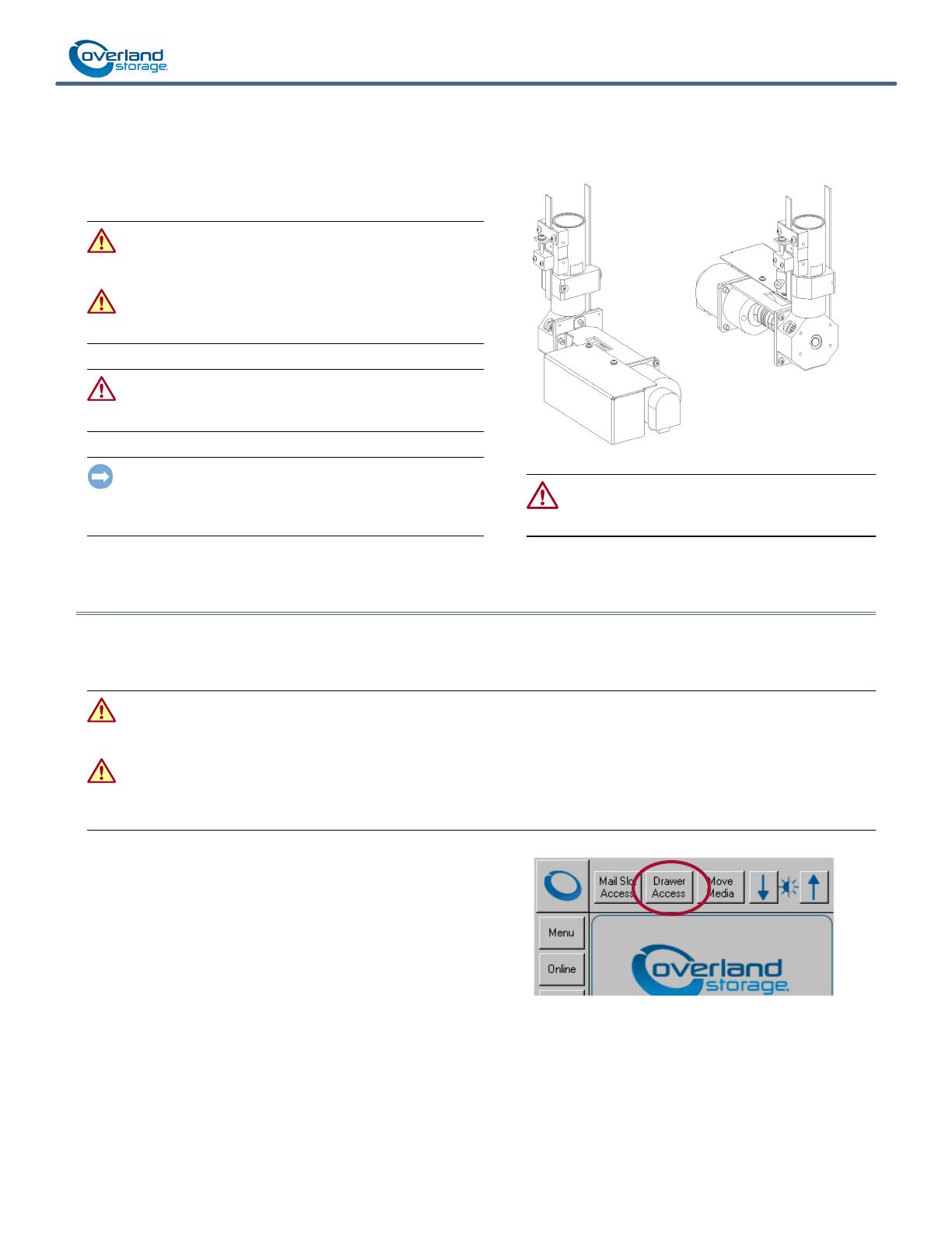
This document describes how to remove and replace a Z-axis
motor assembly of a
Belt Drive Assembly (BDA) in a NEO
8000e tape library from Overland Storage.
WARNING: To reduce the risk of electric shock or damage to
equipment, always remove any power cords while working
with the unit.
AVERTISSEMENT: Pour réduire le risque de choc électrique
ou endommagement de l'équipement, retirez toujours les
cordons électriques en travaillant avec l'appareil.
CAUTION: While working with the unit, observe standard
Electrostatic Discharge (ESD) precautions to prevent damage
to micro-circuitry or static-sensitive devices.
IMPORTANT: Overland Storage requires that the Z-axis motors
be removed and replaced by an Overland Storage authorized
service provider. Improper installation may result in damage which
voids existing warranties.
CAUTION: NEVER handle the BDA with your bare
hands. Contamination from the oils on your skin can
cause the BDA to stick. Always wear cotton gloves.
Prepare the Library
Prepare Media Drawers for Removal
To simplify the replacement of the motor, remove the media drawers to provide easier access to the inside of the library.
WARNING: Exercise care when removing the media drawers from the library units. Fully-loaded drawers weigh approximately 58
pounds (26.3 kg). Also, when the drawers are removed, the inner rails extend several inches beyond the back of the drawers.
Tilting the drawers can result in the tapes falling out. Opening several drawers at once is a tip hazard.
AVERTISSEMENT: Soyez prudent lorsque vous retirez les tiroirs de support des unités de bibliothèque. À pleine charge tiroirs
pèsent environ 26,3 kg. En outre, lorsque les tiroirs sont enlevés, les rails intérieurs s'étendent au-delà de quelques centimètres
à l'arrière des tiroirs. Inclinant les tiroirs peuvent se traduire par des bandes de tomber. Ouverture de plusieurs tiroirs à la fois un
danger pointe.
1. Label all the drawers (so they can be returned to their
correct positions).
2. At the front panel, select Drawer Access (and password,
if active) > Unlock All to release all the media drawers.
NOTE: If the library is partitioned, the partition selection option
is displayed before the access option screen.
3. Pull each drawer out about 2 inches (5cm).
10400536-001 Nov 2013 ©2013 Overland Storage, Inc. Page 2 of 5
Spare Z-axis Motor Assembly Instructions
Remove Media Drawers
1. To remove each media drawer:
IMPORTANT: If removing tapes minimize the weight on a
partitioned library, be sure to keep them together on a
secure surface and labeled so they can be returned to the same
drawer.
a. Pull the drawer out until it stops.
b. Press the drawer release and slide the drawer out a
couple more inches.
c. Carefully remove the drawer, label it, and set it aside.
2. For safety, slide the rails back into the unit using the rear
release buttons on the rails.
Power Off and Disconnect
1. On the front GUI panel, press
Powe r
to turn the library
OFF.
The shuttle/track assembly moves to the library floor as
the unit shuts down.
NOTE: If the library is non-functional, wait until the shuttle/
track assembly finishes drifting to the bottom automatically.
2. At the rear, in the bottom left corner, turn OFF the
circuit breakers.
3. Remove and retain all power cords.
Front Panel Assembly Removal
The Front Panel Assembly (FPA) is held in place with four
screws. The two at the bottom are panhead screws and the two
at the top are flathead.
1. Open both front doors.
2. At the bottom on the left side of the FPA (in front of the
bottom trim) remove the bottom screw.
3. Repeat Step 2 for the right-side bottom FPA screw.
4. Also on the right, remove the top FPA screw.
5. While holding the FPA to prevent stress on the inside
cables, carefully remove the left-side top FPA screw
6. Carefully move the FPA out and reach inside to disconnect
the J3 Connector from the top of the old controller card.
7. Open the retainer clamps above the controller card to
release the J3 cable from the FPA.
8. Carefully remove the FPA and set it on a secure surface.
Remove These
Media Drawers
Remove These
Media Drawers
Circuit Breakers
Unplug J3
Connector
J 3
J 6
J 5
J 2
J 4
2 Flathead Screws
2 Panhead Screws
FPA
(Located Inside)
10400536-001 Nov 2013 ©2013 Overland Storage, Inc. Page 3 of 5
Spare Z-axis Motor Assembly Instructions
Replace Motor
NOTE: The instructions are the same for both the front or rear
motors.
Disconnect BDA Wiring
1. Put on the supplied cotton gloves.
IMPORTANT: Always wear cotton gloves while working
around the BDA to prevent contamination of the guide
pole.
2. Disconnect the BDA wiring:
a. At the front, remove and retain the two screws
securing the Drive PWA cover.
b. Unplug the J2, J3, and J4 connectors from the Drive
PWA.
c. For protection, loosely reattach the Drive PWA cover
using the retained screws (don’t fully tighten).
Replace Drive Motor
Remove the motor assembly from the LHA:
1. Rotate the drive’s helical coupling until the cap screws
are visible.
2. Using a 7/64” hex key, loosen (but don’t remove) the front
cap screw on the helical coupling.
3. Using a 3mm ballhead hex key, remove and retain the
three cap screws holding the motor bracket to the LHA.
4. Set the motor assembly aside on a secure ESD surface.
5. Slide the motor helical coupling of the new motor onto
the LHA shaft.
Make sure the shaft flat side is properly aligned under the
helical coupling cap screws.
6. Using a 3mm ballhead hex key, attach the motor bracket
to the LHA using the three retained cap screws.
7. Using a 7/64” hex key, tighten the front cap screw on the
drive’s helical coupling.
Reconnect BDA Wiring
1. Remove and retain the two screws securing the Drive
PWA cover on the new motor assembly.
2. Attach the J2, J3, and J4 cables to the Drive PWA.
3. Reattach the cover the Drive PWA using the retained
screws (don’t fully tighten).
Drive PWA Cover
Screws
J2
J6
J5
J4
J3
Unplug Cables
Remove These
Three Cap Screws
Drive PWA
Drive Motor
Loosen Front Cap Screw
Lower
Housing
Assembly
Motor Bracket
(LHA)
J2
J6
J5
J4
J3
Attach Cables
10400536-001 Nov 2013 ©2013 Overland Storage, Inc. Page 4 of 5
Spare Z-axis Motor Assembly Instructions
Reassemble the Library & Test
Reattach the FPA
1. At the front of the library, position the FPA in front of the
center opening.
2. Reach inside and reattach the J3 cable to the top of the
controller card.
3. Close the retainer clamps over the J3 cable to secure it.
4. Move the J3 cable behind the BDA top tensioner to keep
it out of the way of the robotics.
Check that the cable is flat against the FPA.
5. Position the FPA so that the screw holes are visible.
6. At the top of the FPA, reinstall the two flathead screws.
7. At the bottom of the FPA reinstall the two panhead
screws.
Reinsert Media Drawers
NOTE: Verify that the tape media is flush in the drawers before
pushing them into the library.
For each drawer:
1. Extend the rails for the appropriate drawer and move the
bearings to the front.
2. Using the identifying label, reinsert the appropriate
drawer onto the rails.
3. Slide the drawer 80% into the library and back out to
check it.
4. Push the drawer all the way in until it locks.
Power On the Library
1. Reattach all the power cords.
2. Set the library circuit breakers to the ON (“|”) position.
The library automatically powers on and completes a
POST.
The touchscreen should show the POST progress indicating it
is fully functioning. If not, contact Overland Technical Support.
Attach J3
Connector
J 3
J 6
J 5
J 2
J 4
2 Flathead Screws
2 Panhead Screws
FPA
(Located Inside)
Circuit Breakers
10400536-001 Nov 2013 ©2013 Overland Storage, Inc. Page 5 of 5
Spare Z-axis Motor Assembly Instructions
Calibration Test
NOTE: The library uses Calibration Fiducial labels to accurately
locate reference points on the Drawer Assemblies, the Fixed
Drawer Assembly and the Mail Slot Track Assembly.
Calibration Fiducial Label locations:
Two on the drive bay bulkhead
Two on each Drawer
Two on the Fixed Slots
Two on the Mail Slot track
NEO 8000e libraries uses the picker to touch these fiducial
label posts during a calibration routine to establish the
reference points it needs.
1. Cartridges in the immediate area of the Fiducial labels
must be removed to avoid any interference when touching
or reading the labels:
Remove the cartridges in the first five and last five
slots in rows numbered two and three in each drawer
that has cartridges.
In addition, for the middle-left drawer, remove
the first five and last five cartridges in the top row.
Also, for the middle-right drawer, remove all the
cartridges in the top row.
Remove the cartridges in the first five and last five
slots in the Fixed Slots.
Remove the Mail Slot Magazine.
2. At the default front panel menu, press Maintenance >
Calibrate Robot.
3. Leave all elements checked for a full calibration of all
drawers and magazines.
Test requires 30-35 minutes to complete.
Return Old Parts to Overland
1. Place the old part in the anti-static bag and put it in the
replacement part’s box.
2. Use an RMA to return the part to Overland Storage.
For return shipping details and RMA number, go to:
http://docs.overlandstorage.com/return-instructions
Empty
Slots
Media Drawers
Also
Remove
Middle-left Drawer
Also
Remove
Middle-right Drawer
  • Page 1 1
  • Page 2 2
  • Page 3 3
  • Page 4 4
  • Page 5 5

Overland Storage NEO 8000E Assembly Instructions

Taper
Assembly Instructions

dans d''autres langues