NOMA LEVI Le manuel du propriétaire
- Catégorie
- Ventilateurs ménagers
- Taper
- Le manuel du propriétaire

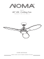
USER MANUAL
READ AND SAVE THESE INSTRUCTIONS
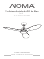
Levi
48" LED Ceiling Fan
PRODUCT NO. 052-9605-4

TABLE OF CONTENTS
2

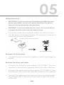
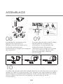
01. SAFETY/CAUTIONS
02. TOOLS REQUIRED
03. EXPLODED VIEW
04. ELECTRICAL SAFETY
05. ASSEMBLY
06. OPERATION
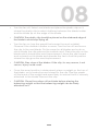
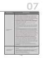
07. TROUBLESHOOTING
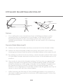
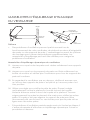
08. DYNAMIC BLADE BALANCING KIT
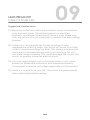
09. MAINTENANCE
10. WARRANTY & DISPOSAL
4
6
7
10
12
19
21
23
25
26
3

SAFETY / CAUTIONS
•
•
•
•
•
•
•
•
•
•
TO REDUCE THE RISK OF ELECTRIC SHOCK, ENSURE ELECTRICITY HAS
BEEN TURNED OFF AT THE CIRCUIT BREAKER OR FUSE BOX BEFORE
BEGINNING.
ALL WIRING MUST BE IN ACCORDANCE WITH NATIONAL AND
LOCAL ELECTRICAL CODES. ELECTRICAL INSTALLATION SHOULD BE
PERFORMED BY A QUALIFIED LICENSED ELECTRICIAN.
WARNING: TO REDUCE THE RISK OF ELECTRIC SHOCK OR FIRE, DO
NOT USE THIS FAN WITH ANY SOLID-STATE FAN-SPEED CONTROL
DEVICE. IT WILL PERMANENTLY DAMAGE THE ELECTRONIC CIRCUITRY.
CAUTION: TO REDUCE THE RISK OF PERSONAL INJURY, USE ONLY THE
SCREWS PROVIDED WITH THE OUTLET BOX.
THE OUTLET BOX AND SUPPORT STRUCTURE MUST BE SECURELY
MOUNTED AND CAPABLE OF RELIABLY SUPPORTING A MINIMUM OF
50 LB (22.7 KG). USE ONLY UL-LISTED OUTLET BOXES MARKED “FOR FAN
SUPPORT.”
THE FAN MUST BE MOUNTED WITH A MINIMUM OF 6´11˝ (2.1 M) FROM
THE TRAILING EDGE OF THE BLADES TO THE FLOOR.
AVOID PLACING OBJECTS IN THE PATH OF THE BLADES.
TO AVOID PERSONAL INJURY OR DAMAGE TO THE FAN AND OTHER
ITEMS, BE CAUTIOUS WHEN WORKING AROUND OR CLEANING THE
FAN.
DO NOT USE WATER OR DETERGENTS WHEN CLEANING THE FAN
OR FAN BLADES. A DRY DUST CLOTH WILL BE SUITABLE FOR MOST
CLEANING.
AFTER MAKING ELECTRICAL CONNECTIONS, SPLICED CONDUCTORS
SHOULD BE TURNED UPWARD AND PUSHED CAREFULLY UP INTO
THE OUTLET BOX. THE WIRES SHOULD BE SPREAD APART WITH THE
GROUNDED CONDUCTOR AND THE EQUIPMENT-GROUNDING
CONDUCTOR ON ONE SIDE OF THE OUTLET BOX AND THE
UNGROUNDED CONDUCTOR ON THE OTHER SIDE OF THE OUTLET BOX.
ALL SET SCREWS MUST BE CHECKED AND RE-TIGHTENED WHERE
NECESSARY BEFORE INSTALLATION.
4

WARNING: CHEMICAL BURN HAZARD. KEEP BATTERIES AWAY FROM
CHILDREN. THIS PRODUCT CONTAINS A LITHIUM BUTTON/COIN CELL
BATTERY. IF A NEW OR USED LITHIUM BUTTON/COIN CELL BATTERY IS
SWALLOWED OR ENTERS THE BODY, IT CAN CAUSE SEVERE INTERNAL
BURNS AND CAN LEAD TO DEATH IN AS LITTLE AS 2 HOURS. ALWAYS
COMPLETELY SECURE THE BATTERY COMPARTMENT. IF THE BATTERY
COMPARTMENT DOES NOT CLOSE SECURELY, STOP USING THE
PRODUCT, REMOVE THE BATTERIES, AND KEEP IT AWAY FROM
CHILDREN. IF YOU THINK BATTERIES MIGHT HAVE BEEN SWALLOWED OR
PLACED INSIDE ANY PART OF THE BODY, SEEK IMMEDIATE MEDICAL
ATTENTION.
A) THE CELLS SHALL BE DISPOSED OF PROPERLY, INCLUDING KEEPING
THEM AWAY FROM CHILDREN; AND
B) EVEN USED CELLS MAY CAUSE INJURY.
01
•
•
•
•
WARNING: TO REDUCE THE RISK OF FIRE, ELECTRIC SHOCK
AND PERSONAL INJURY, MOUNT FAN TO OUTLET BOX MARKED
“ACCEPTABLE FOR FAN SUPPORT” WITH THE SCREWS PROVIDED WITH
THE OUTLET BOX.
WARNING: TO AVOID RISK OF PERSONAL INJURY, DO NOT BEND THE
BLADE ARMS (ALSO REFERRED TO AS FLANGES) OR THE BRACKETS
WHILE BALANCING THE BLADES OR CLEANING THE FAN. DO NOT
INSERT FOREIGN OBJECTS BETWEEN ROTATING FAN BLADES.
WARNING: TO REDUCE THE RISK OF FIRE, ELECTRIC SHOCK
AND PERSONAL INJURY, MOUNT FAN TO OUTLET BOX MARKED
“ACCEPTABLE FOR FAN SUPPORT OF 50 LB (22.7 KG) OR LESS”
AND USE MOUNTING SCREWS PROVIDED WITH THE OUTLET BOX.
MOST OUTLET BOXES COMMONLY USED FOR THE SUPPORT OF
LIGHT FIXTURES ARE NOT ACCEPTABLE FOR FAN SUPPORT AND MAY
NEED TO BE REPLACED. DUE TO THE COMPLEXITY OF THIS FAN, A
QUALIFIED LICENSED ELECTRICIAN IS STRONGLY RECOMMENDED FOR
INSTALLATION.
ATTENTION: PLEASE ENSURE LED BULBS’ TOTAL WATTAGE IS ALWAYS
•
BELOW 70 W!
5

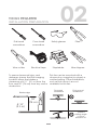
02
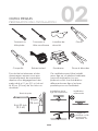
TOOLS REQUIRED
INSTALLATION PREPARATION
Flat-head
screwdriver
Cross-head
screwdriver
Safety glasses Pliers
Wire cuttersElectrical tape Stepladder Wire strippers
6´11˝
(2.1 m)
30”
(76 cm)
To prevent personal injury and
damage, ensure that the hanging
location allows the blades a
clearance of 6´11˝ (2.1 m) from the
floor and 30” (76 cm) from any wall or
obstruction.
This fan can be mounted with a
downrod on a regular (no-slope) or
vaulted ceiling. Other installations,
such as flush mount, are not
available for this fan.
Blade edge
Downrod
installation installation
Flush mount
Vaulted
ceiling angle
is not to
exceed 18°.
6

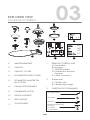
02 03
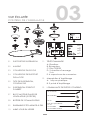
EXPLODED VIEW
PACKAGE CONTENTS
01.
02.
03.
04.
05.
06.
07.
08.
09.
10.
HANGER BRACKET
CANOPY
CANOPY COVER
DOWNROD STAND COVER
DOWNROD, HANGER PIN
& LOCK PIN
FAN MOTOR ASSEMBLY
FAN BLADES (3 PCS)
SWITCH HOUSING
LED LIGHT KIT
GLASS SHADE
11.
12.
13.
REMOTE CONTROL UNIT
A. Transmitter
B. Receiver
C. CR2032 battery
D. 2 Expansion anchors
2 screws
E. 4 Wire connector
Balance kit
A. 1 Plastic clip
B. 2 Balancing weight
PARTS PACK CONTAINING:
01
02
08
03
04 09
05
06
07
10
13
x 2
x 2
x 2
x 1
2x wood screws
2x washes
2x screws
Cable Hardware Bag
1x screw
1x washer
1x split washer
x 2 x 2 x 4
A B
E
11
DC
12
5g
x 1
x 2
7

EXPLODED VIEW
DETAIL
01. CLEVIS PIN
02.
03.
04.
05.
06.
07.
08.
09.
FAN BLADE
LIGHT KIT
HANGER BRACKET
HANGER BALL
CANOPY
CANOPY COVER
DOWNROD
DOWNROD STAND
COVER
10.
11.
12.
13.
14.
HAIRPIN CLIP
COLLAR
FAN MOTOR
ASSEMBLY
SWITCH HOUSING
GLASS SHADE
03
8

03
03
01
02
04
05
06
07
08
11
09
10
12
13
14
9

ELECTRICAL SAFETY
Instructions
•
01.
02.
03.
04.
Making the Electrical Connections
•
•
Read all safety information and installation instructions before
you begin to install the fan and save instructions.
All set screws of the fan must be checked and re-tightened
where necessary before installation.
To reduce the risk of personal injury, do not bend the blade
brackets when installing the brackets, balancing the blades
or cleaning the fan. Do not insert foreign objects between
rotating fan blades.
Before changing the fan direction, turn off the fan and wait for
the fan blades to stop completely.
The safeguards provided by these safety instructions and by
the separate installation instructions are not meant to cover all
possible conditions and situations that may occur. It must be
understood that common sense, caution and care are factors
which cannot be built into this product. These factors must be
supplied by the person(s) installing, caring for and operating
the fan.
WARNING: To avoid risk of electric shock, be sure to shut off
power at the main fuse or circuit breaker box before installing
or servicing this fixture. Turning off the electrical power by using
the light switch is not sufficient to prevent electric shock.
To reduce the risk of injury, install the fan so that the blades are
at least 6´ 11˝ (2.1 M) above the floor and at least 30” (76 cm)
from the tip of the blades to the wall.
10

04
•
•
•
•
•
mount the outlet box marked “ACCEPTABLE FOR FAN
To reduce the risk of flre, electric shock, or personal injury,
SUPPORT” and use mounting screws provided with the outlet
box.
The installation must be in accordance with national
electrical code, ANSI/NFPA 70-1999 and local codes. If you
are unfamiliar with the methods of installing electrical wiring,
seek the services of a qualified licensed electrician.
injury, mount to outlet box and use mounting screws provided
WARNING: To reduce the risk of fire, electric shock, or personal
with the outlet box.
IMPORTANT: Before you begin installing the fan, carefully read
all information on the separate sheet “SAFETY INSTRUCTIONS”
as well as the following “Installation Steps”. If in doubt, consult
a qualified electrician.
NOTE: The fan weight is 11 lb 14 oz (5.4 kg). Be sure the outlet
box you are using is securely attached to the building structure
and can support the full weight of the fan. Failing to do so can
result in serious injury.
11

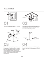
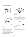
Turn OFF the electric circuit at the main
fuse of circuit breaker box.
01
Securely attach the mounting bracket to
an outlet box marked “ACCEPTABLE FOR
FAN SUPPORT” using the supplied outlet
box screws with spring washers.
02
03 04
ASSEMBLY
Mounting
bracket
Outlet box
screw
Spring
washer
Outlet
box
Set scew
Hanger ball
Downrod
Pin
Hairpin clip
Clevis pin
Remove the hanger ball portion from
the downrod/hanger ball assembly by
loosening the set screw in the hanger
ball until the ball falls freely down the
downrod. Remove the pin from the
downrod, then remove the hanger ball.
Retain the pin and hanger ball for
reinstallation.
Remove the hairpin clip and clevis pin
from the bottom of the downrod. Retain
the pin and clip for reinstallation for next
step.
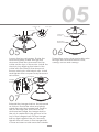
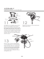
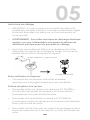
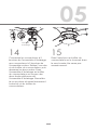
12

05
Canopy
05 06
Canopy
cover
Downrod
stand cover
07
Collar
Clevis pin
Set screw
Hairpin clip
Loosen the two set screws. Route the
wires and safety cable through the
downrod. Slide the downrod into the
collar on the top of the motor. Install the
clevis pin by aligning the holes in the
collar with the holes in the downrod.
Secure clevis pin with hairpin clip. Install
and tighten the two previously removed
set screws.
Thread the motor wires and cable wire
through the downrod stand cover,
canopy cover and canopy.
Reinstall the hanger ball on the downrod
as follows. Route the wires and safety
cable through the hanger ball. Position
the pin through the two holes in the
downrod and align the hanger ball so
the pin is captured in the groove in the
top of the hanger ball. Pull the hanger
ball up tight against the pin. Securely
tighten the set screw in the hanger ball.
A loose set screw could cause fan wobble.
Downrod
Hanger
ball
13

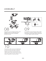
ASSEMBLY
For added security attach safety cable
from fan “J” hook in outlet box. Secure
looping zip tie through safety cable and
“J” hook. Tighten zip tie securely.
09
Safety
cable “J”
hook
Tighten
zip tie
Zip
tie
08
Hang the fan on hanger bracket, and
make sure the slot of hanger ball is
snapped into the clip of hanger
bracket exactly.
NO
OK
10
The safety cable must be installed into
the house structure beams using a 3”
lag screw. Make sure that when the
safety cable is fully extended the lead
wires are longer than the cable and no
stress is placed on the lead wires.
14

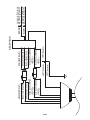
05
IMPORTANT: If you are not sure if the electrical outlet box and
fan are grounded, contact a licensed electrician for advice.
They must be grounded for safe operation.
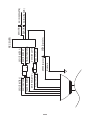
WARNING: To avoid possible electric shock, be sure electricity
is turned off at the main fuse box before wiring.
Once the connection has been made, the receiver inserts
into the drop rod hanging bracket. The canopy comes up to
cover the receiver and bracket.
Wiring Instructions
•
•
•
DO NOT CUT THIS - As this is the antenna
VIEW AFTER INSTALLATION
Between Fan & Receiver
Connect the pin connectors together, refer to next page for
details.
•
Between Receiver and Mains
Connect the black live wire marked ”AC POWER L” from the
receiver to the live wire (typically black) from the outlet box.
•
Connect the white neutral wire marked ”AC POWER N” from
the receiver to the neutral wire (typically white) from the outlet box.
•
Connect the green ground wire from the mounting bracket
and hanger ball to the ground wire bare or green from the
outlet box.
•
15

AC IN N(WHITE)
AC IN L(BLACK)
YELLOW ("TO MOTOR U")
RECEIVER
YELLOW ("TO MOTOR U")
RED ("TO MOTOR W")
BLUE ("FOR LIGHT L")
WHITE ("FOR LIGHT N")
RED ("TO MOTOR W")
BLUE ("FOR LIGHT L")
WHITE ("FOR LIGHT N")
GREEN (Ground wire)
Ground wire
GREY ("TO MOTOR V") GREY ("TO MOTOR V")
GREEN (Ground wire)
WHITE
BLACK
16

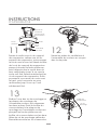
ASSEMBLY
INSTRUCTIONS - CONTINUED
Half-tighten one hanger bracket screw,
remove one hanger bracket screw,
then push the canopy upwards and let
the hanger bracket screw head come
through the key hole slot, then rotate the
canopy counter-clockwise until canopy
is secured. Now, tighten hanger bracket
screws. Finally, push the canopy cover
upward, then turn it counter-clockwise
until it is secure.
11
Hanger
bracket
Hanger
bracket screw
Canopy
Canopy
screw
Key
hold slot
Canopy
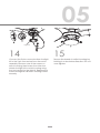
cover
Tighten fan blades to motor assembly by
using blade screws.
12
Remove one of the mounting screws
on mounting plate of motor assembly,
then loosen the other two. Attach the
switch housing to the mounting plate
on the motor assembly by placing the
keyhole slots from the switch housing
onto the two protruding mounting
screw heads. Then put back the screws
and tighten them.
13 Mounting
screw
Switch
housing
1
2
17

Connect the 2-pin connectors from the light
kit to the 2-pin connectors from the motor
assembly. Remove one of the screws on
switch housing then loosen the other two.
Attach the light kit to switch housing using
the two key slots in the light kit. Replace the
screw and tighten all switch housing screws
securely.
14
Light kit
1
2
3
05
Secure the shade to switch housing by
twisting in a clockwise direction. Do not
over-tighten.
15
18

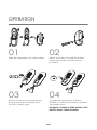
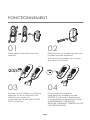
OPERATION
01
Slide the transmitter out of the holder.
02
Select a location to install the holder.
Attach the holder with two screws
provided.
03
Be sure to use a tool to depress the
hook to remove the battery door.
DO NOT forcibly open.
04
To make fan operational, install a
CR2032 3 V battery (included). Replace
the battery door.
WARNING: CHEMICAL BURN HAZARD. KEEP
BATTERY AWAY FROM CHILDREN.
05
19

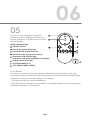
06
IC STATEMENT
This device contains license-exempt transmitter(s)/receiver(s) that comply with
lnnovation, Science and Economic Development Canada’s license-exempt RSS(s).
Operation is subject to the following two conditions:
1. This device may not cause interference.
2. This device must accept any interference, including interference that may cause
undesired operation of the device.
Turn fan on/off and select fan speed.
LED indicated light
ON/OFF the fan
Turn up the speed of the fan
Turn down the speed of the fan
Direction of the fan (reverse switch)
Timing control of the fan
3V CR2032 battery X 1
CCT: 3000 K/4000 K/5000 K
Short press: ON/OFF the light
Long press: Adjust the brightness of the light
Restore power to ceiling fan and test for
proper operation. The fan remote controls
the fan settings.
05
8
8
9
9
1h 3h 6h
20
La page est en cours de chargement...
La page est en cours de chargement...
La page est en cours de chargement...
La page est en cours de chargement...
La page est en cours de chargement...
La page est en cours de chargement...
La page est en cours de chargement...
La page est en cours de chargement...
La page est en cours de chargement...
La page est en cours de chargement...
La page est en cours de chargement...
La page est en cours de chargement...
La page est en cours de chargement...
La page est en cours de chargement...
La page est en cours de chargement...
La page est en cours de chargement...
La page est en cours de chargement...
La page est en cours de chargement...
La page est en cours de chargement...
La page est en cours de chargement...
La page est en cours de chargement...
La page est en cours de chargement...
La page est en cours de chargement...
La page est en cours de chargement...
La page est en cours de chargement...
La page est en cours de chargement...
La page est en cours de chargement...
La page est en cours de chargement...
La page est en cours de chargement...
La page est en cours de chargement...
La page est en cours de chargement...
La page est en cours de chargement...
La page est en cours de chargement...
La page est en cours de chargement...
La page est en cours de chargement...
La page est en cours de chargement...
-
 1
1
-
 2
2
-
 3
3
-
 4
4
-
 5
5
-
 6
6
-
 7
7
-
 8
8
-
 9
9
-
 10
10
-
 11
11
-
 12
12
-
 13
13
-
 14
14
-
 15
15
-
 16
16
-
 17
17
-
 18
18
-
 19
19
-
 20
20
-
 21
21
-
 22
22
-
 23
23
-
 24
24
-
 25
25
-
 26
26
-
 27
27
-
 28
28
-
 29
29
-
 30
30
-
 31
31
-
 32
32
-
 33
33
-
 34
34
-
 35
35
-
 36
36
-
 37
37
-
 38
38
-
 39
39
-
 40
40
-
 41
41
-
 42
42
-
 43
43
-
 44
44
-
 45
45
-
 46
46
-
 47
47
-
 48
48
-
 49
49
-
 50
50
-
 51
51
-
 52
52
-
 53
53
-
 54
54
-
 55
55
-
 56
56


NOMA LEVI Le manuel du propriétaire
- Catégorie
- Ventilateurs ménagers
- Taper
- Le manuel du propriétaire
dans d''autres langues
- English: NOMA LEVI Owner's manual