
sauder.com
Computer Desk
Model 411606
NOTE: THIS INSTRUCTION
BOOKLET CONTAINS IMPORTANT
SAFETY INFORMATION.
PLEASE READ AND KEEP FOR
FUTURE REFERENCE.
English pg 1-17
Français pg 18-20
Español pg 21-23
Lot # 529997 05/24/19
Purchased: __________________
sauder.com
CONTACT US FIRST
BEFORE MAKING ANY RETURNS TO THE STORE.
Share your journey!
sauder.com
CONTACT US FIRST
BEFORE MAKING ANY RETURNS TO THE STORE.
Visit sauder.com/service to order replacement parts, view video assembly tips, or chat with a live rep.
Prefer the phone? Give us a ring at
1-800-523-3987.
Customer Service is available Monday-Friday - 9 a.m. to 5:30 p.m. EST (except holidays)
Sit and surf.

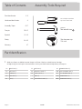
Table of Contents Assembly Tools Required
2-3
4
5-17
18-20
21-23
24-26
27
Part Identifi cation
Hardware Identifi cation
Assembly Steps
Français
Español
Safety
Warranty
Hammer
Not actual size
No. 2 Phillips Screwdriver
Tip Shown Actual Size
Skip the power trip.
This time.
411606 www.sauder.com/servicePage 2
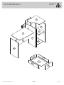
Part Identifi cation
å While not all parts are labeled, some of the parts will have a label or an inked letter on the edge
to help distinguish similar parts from each other. Use this part identifi cation to help identify similar parts.
A3 RIGHT END (1)
B3 LEFT END (1)
C3 UPRIGHT (1)
D3 DESK TOP (1)
E2 TOP (1)
F3 BOTTOM (1)
G3 MODESTY PANEL (1)
H3 SMALL BACK (1)
I BACK (1)
J2 ADJUSTABLE SHELF (1)
K2 DRAWER FRONT (1)
D20 RIGHT DRAWER SIDE (1)
D21 LEFT DRAWER SIDE (1)
D148 DRAWER BACK (1)
D951 DRAWER BOTTOM (1)

Part Identifi cation
Now you know
our ABCs.
411606www.sauder.com/service
Page 3
A3
B3
C3
D3
E2
F3
G3
H3
I
J2
K2
D20
D21
D951
D148

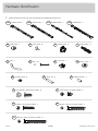
Hardware Identifi cation
å Screws are shown actual size. You may receive extra hardware with your unit.
411606 www.sauder.com/servicePage 4
CORD CLIP - 1
4P
RUBBER SLEEVE - 4
2R
METAL PIN - 5
1R
PULL - 1
1K
SLIDE CAM - 2
10A
TACK GLIDE - 6
12E
35DA
CABINET RIGHT - 1
35DB
CABINET LEFT - 1
35DC
DRAWER RIGHT - 1
35DD
DRAWER LEFT - 1
HIDDEN CAM - 6
1F
CAM DOWEL - 6
2F
BROWN 1" FLAT HEAD SCREW - 2
12S
BLACK 9/16" LARGE HEAD SCREW - 6
1S
GOLD 5/16" FLAT HEAD SCREW - 8
3S
NAIL - 10
1N
SCREW COVER - 6
20P
CAM COVER - 2
12P
BLACK 1-15/16" FLAT HEAD SCREW - 12
113S
30S
BLACK 1-9/16" FLAT HEAD SCREW - 4

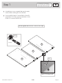
Step 1
Look for this icon. It means a
video assembly tip is available at
www.sauder.com/service/tips
å
Assemble your unit on a carpeted fl oor or on the empty
carton to avoid scratching your unit or the fl oor.
å
Push six HIDDEN CAMS (1F) into the ENDS (A3 and B3)
and UPRIGHT (C3). Then, insert the metal end of a CAM
DOWEL (2F) into each HIDDEN CAM.
411606www.sauder.com/service
Page 5
C3
B3
A3
Arrow
1F
2F
Insert the metal end of the CAM
DOWEL into the HIDDEN CAM.
Arrow
Do not tighten the HIDDEN CAMS in this step.
(6 used)

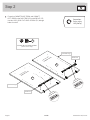
Step 2
å
Fasten the CABINET RIGHT (35DA) and CABINET
LEFT (35DB) to the RIGHT END (A3) and UPRIGHT (C3).
Use four GOLD 5/16" FLAT HEAD SCREWS (3S) through
holes #1 and #3.
411606 www.sauder.com/servicePage 6
A3
C3
1
2
3
1
2
3
3 5 D A
35DA
3 5 D B
35DB
Roller end
Roller end
Finished edge
Finished edge
Surface with
HIDDEN CAMS
Surface with
HIDDEN CAMS
GOLD 5/16" FLAT HEAD SCREW
(4 used in this step)
3S
Remember:
Righty tighty.
Lefty loosey.

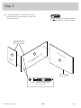
å
Fasten the UPRIGHT (C3) to the DESK TOP (D3)
and BOTTOM (F3). Use four BLACK 1-15/16" FLAT
HEAD SCREW (113S).
Step 3
411606www.sauder.com/service
Page 7
C3
F3
Surface without HIDDEN CAMS
Unfi nished
surface
Do not stand the unit upright without the
BACK fastened. The unit may collapse.
Caution
BLACK 1-15/16" FLAT HEAD SCREW
(4 used in this step)
113S
D3
Curved edge
Unfi nished edge
Surface with holes

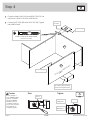
Step 4
å
Fasten the SMALL BACK (H3) to the DESK TOP (D3). Use
two BLACK 1-15/16" FLAT HEAD SCREW (113S).
å
Fasten the LEFT END (B3) to the DESK TOP (D3). Tighten
two HIDDEN CAMS.
411606 www.sauder.com/servicePage 8
D3
H3
Start Tighten
Arrow
Minimum
190 degrees
Caution
Risk of damage or
injury. HIDDEN CAMS
must be completely
tightened. HIDDEN
CAMS that are not
completely tightened
may loosen, and parts
may separate. To
completely tighten:
Arrow
Maximum
210 degrees
Edge with
two holes
Finished edge
For support, place packing
foam and magazines here.
B3
BLACK 1-15/16" FLAT HEAD SCREW
(2 used in this step)
113S
Surface without HIDDEN CAMS
Unfi nished edge

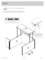
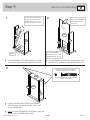
å
NOTE: Start each SCREW a few turns before completely tighening
any of them.
å
Fasten the MODESTY PANEL (G3) to the LEFT END (B3) and
UPRIGHT (C3). Use four BLACK 1-15/16" FLAT HEAD SCREW (113S).
Step 5
411606www.sauder.com/service
Page 9
C3
B3
G3
Unfi nished surface
The hole in the edge of
the MODESTY PANEL
is closer to this edge.
BLACK 1-15/16" FLAT HEAD SCREW
(4 used in this step)
113S

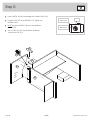
Step 6
å
Insert a METAL PIN (1R) into the edge of the SMALL BACK (H3).
å
Fasten the TOP (E2) to the UPRIGHT (C3). Tighten two
HIDDEN CAMS.
å
NOTE: Be sure the METAL PIN inserts into the hole in
the TOP (E2).
å
Turn a CORD CLIP (4P) into the hole in the bottom
surface of the TOP (E2).
411606 www.sauder.com/servicePage 10
Arrow
Minimum
190 degrees
Maximum
210 degrees
E2
C3
H3
1R
4P
Surface
with
holes

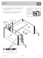
å
Fasten the RIGHT END (A3) to the TOP (E2) and BOTTOM (F3).
Tighten two HIDDEN CAMS and use two BLACK 1-15/16" FLAT
HEAD SCREWS (113S).
å
With a hammer, tap six TACK GLIDES (12E) into the bottom
edges of the ENDS (A3 and B3) and UPRIGHT (C3).
Step 7
411606www.sauder.com/service
Page 11
A3
C3
B3
F3
12E
12E
Arrow
Minimum
190 degrees
Maximum
210 degrees
BLACK 1-15/16" FLAT HEAD SCREW
(2 used in this step)
113S
Surface without HIDDEN CAMS
Unfi nished edge
Tighten two
HIDDEN CAMS
E2

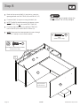
Step 8
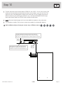
å
Bend the fl ap up on the BACK (I) and then lay it over the
opening between the RIGHT END (A3) and UPRIGHT (C3).
å
Fasten the BACK (I) to your unit using the NAILS (1N).
å
NOTE: The BACK should be touching the bottom surface
of the TOP (E2). Do not nail into the RIGHT END (A3).
å
Fasten the fl ap of the BACK (I) to the RIGHT END (A3).
Use six BLACK 9/16" LARGE HEAD SCREWS (1S).
å
NOTE: Perforations have been provided for access through
the BACK. Carefully cut out the holes needed.
411606 www.sauder.com/servicePage 12
A3
C3
I
B3
E2
Flap
This perforation
should be here.
NAIL
(10 used in this step)
1N
BLACK 9/16" LARGE HEAD SCREW
(6 used in this step)
1S
Do not stand the unit upright without the
BACK fastened. The unit may collapse.
Caution

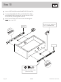
Step 9
411606www.sauder.com/service
Page 13
VIEW THE T-LOCK BOX VIDEO
å
Fasten the DRAWER BACK (D148) to the DRAWER
SIDES (D20 and D21). Use four BLACK 1-9/16" FLAT
HEAD SCREWS (30S).
å
NOTE: Be sure the DRAWER BOTTOM (D951) inserts into
the groove of the DRAWER BACK (D148).
12
3
å
Insert the DRAWER SIDES (D20 and D21) at an angle
into the slot at each end of the DRAWER FRONT (K2).
å
Slide the DRAWER BOTTOM (D951) into the grooves in the
DRAWER SIDES (D20 and D21) and DRAWER FRONT (K2).
The tabs should insert freely
into the slots. Gently tilt the
DRAWER SIDES side to side
until the tabs slip into the slots.
Groove
Be sure the DRAWER
BOTTOM inserts into the
DRAWER FRONT groove.
D20
D21
D951
D951
D20
D21
D148
D21
K2
K2
Unfi nished
surface
With the palm of your
hand, tap the DRAWER
BOTTOM down into
the groove.
D20
Start each screw a few turns before
completely tightening any of them.
BLACK 1-9/16" FLAT HEAD SCREW
(4 used in this step)
30S

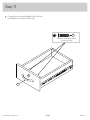
Step 10
å
Insert a SLIDE CAM (10A) into the DRAWER SIDES (D20 and D21).
å
Fasten the DRAWER RIGHT (35DC) and DRAWER LEFT (35DD)
to the DRAWER SIDES (D20 and D21). Use four GOLD 5/16" FLAT
HEAD SCREWS (3S) through holes #1 and #3.
å
NOTE: The screw head in the CAM must be visible through the
slotted hole in the SLIDE.
411606 www.sauder.com/servicePage 14
10A
10A
3 5 D C
35DC
3 5 D D
35DD
Screw head - turn CAM to line
up the holes in the SLIDES with
holes in the DRAWER SIDES.
1
2
3
1
2
3
GOLD 5/16" FLAT HEAD SCREW
(4 used in this step)
3S
Roller end
Roller end
D20
D21

å
Fasten the PULL (1K) to the DRAWER FRONT (K2). Use
two BROWN 1" FLAT HEAD SCREWS (12S).
Step 11
411606www.sauder.com/service
Page 15
1K
K2
BROWN 1" FLAT HEAD SCREW
(2 used in this step)
12S

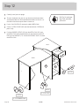
Step 12
å
Carefully stand your unit upright.
å
To insert the drawer into your unit, tip the front of the drawer down
and drop the rollers on the drawer behind the rollers on the unit. Lift
the front of the drawer up and slide it into the unit.
å
Push a CAM COVER (12P) onto each visible HIDDEN CAM.
å
Center a SCREW COVER (20P) over the head of each SCREW and
press fi rmly.
å
Push the RUBBER SLEEVES (2R) over the METAL PINS (1R). Insert
the METAL PINS into the hole locations of your choice in the RIGHT
END (A3) and UPRIGHT (C3). Set the ADJUSTABLE SHELF (J2) onto
the METAL PINS.
411606 www.sauder.com/servicePage 16
A3
C3
J2
12P
20P
1R
2R
25 lbs.
40 lbs.
20 lbs.
40 lbs.
5 lbs.
To cover screws
To cover HIDDEN CAMS
(4 used)
(2 used)
(6 used)
Pro Tip: Lift with your
legs. And, you know,
your arms.

å
To make adjustments to the drawer, loosen SCREW #3 in the SLIDES a 1/4 turn, then turn the CAM
clockwise or counter-clockwise. Notice how the drawer raises or lowers as you turn the CAM. The
higher the screw in the oblong hole, the higher your drawer front will be. The lower the screw, the
lower the drawer front. By adjusting the drawer this way, it will help the DRAWER FRONT line up
better when closed. Tighten the SCREWS when fi nished with adjustments.
å
NOTE: Please read the back pages of the instruction booklet for important safety information.
å
This completes assembly. Clean with your favorite furniture polish or a damp cloth. Wipe dry.
Step 13
411606www.sauder.com/service
Page 17
Cam
Loosen screw #3 a 1/4 turn, turn the cam a 1/4 turn
maximum in both the clockwise and counter-clockwise
directions to make adjustments, and then tighten screw #3.
The higher the screw in the oblong hole,
the higher your drawer front will be. The
lower the screw, the lower the drawer front.
And to celebrate, why not share your success story at Walmart.com or

A l’usage exclusif du
Canada Noter la date
d’achat de cet élément
et conserver le livret
pour future référence.
Pour contacter Sauder
en ce qui concerne cet
élément, faire référence
au numéro de lot et
numéro de modèle en
appelant notre numéro
sans frais.
Lot nº : ____________
Date de
l’achat: ____________
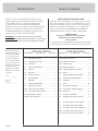
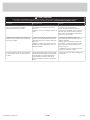
LISTE DE PIÈCES
REFERENCE DESCRIPTION QUANTITÉ
LISTE DE PIÈCES
REFERENCE DESCRIPTION QUANTITÉ
NOUS SOMMES LA POUR VOUS AIDER!
Nous faisons de notre mieux pour nous assurer que votre meuble
arrive dans d’excellentes conditions. Nos représentants du service
Clientèle sont aimables et prêts à vous aider au cas où une pièce
aurait été endommagée ou manquerait (ou si vous aviez besoin
d’aide pour l’assemblage). NE RAMENEZ PAS LE MEUBLE AU
MAGASIN. Au Canada, composez ce numéro d’appel gratuit:
1-800-523-3987
Du lundi au vendredi, de 9 heures du matin à
5:30 heures du soir (horaire Côte Est)
(sauf jours fériés)
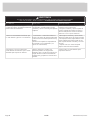
Si une pièce a besoin d’être remplacée, la pièce de remplacement
sera envoyée dans les 48 heures. (Sauf week-ends et jours fériés)
Utilisez les instructions d’assemblage en français avec les
schémas étape par étape du manuel d’instruction en anglais.
Chaque étape en français correspond à la même étape
en anglais. La pièce devant être attachée à l’élément est
représentée en gris sur les schémas de chaque étape pour plus
de précision. Comparer la “Liste de pièces” ci-dessous avec
la “PART IDENTIFICATION” du manuel en anglais pour vous
familiariser avec les pièces avant l’assemblage.
REMARQUE : CE MANUEL D’INSTRUCTIONS CONTIENT
D’IMPORTANTES INFORMATIONS RELATIVES À LA SÉCURITÉ.
À LIRE ET CONSERVER POUR TOUTE RÉFÉRENCE FUTURE.
Bureau d'ordinateurModèle 411606
35DA
ÉLÉMENT DROITE.......................................................1
35DB
ÉLÉMENT GAUCHE ...................................................1
35DC
TIROIR DROIT .................................................................1
35DD
TIROIR GAUCHE ...........................................................1
10A EXCENTRIQUE DE COULISSE .........................2
12E PATIN .....................................................................................6
1F EXCENTRIQUE ESCAMOTABLE .....................6
2F CHEVILLE D'EXCENTRIQUE ..............................6
1K POIGNÉE .............................................................................1
1N CLOU .................................................................................10
4P CLIP POUR CORDONS ...........................................1
12P COUVERCLE D'EXCENTRIQUE .......................2
20P CACHE-VIS ......................................................................6
1R GOUPILLE EN MÉTAL .............................................5
2R MANCHON EN CAOUTCHOUC .....................4
1S VIS TÊTE LARGE 14 mm NOIRE .....................6
3S VIS TÊTE PLATE 8 mm DORÉE ......................8
12S VIS TÊTE PLATE 25 mm MARRON .............2
30S VIS TÊTE PLATE 40 mm NOIRE ....................4
113S VIS TÊTE PLATE 49 mm NOIRE ...................12
A3 EXTRÉMITÉ DROITE ..................................................1
B3 EXTRÉMITÉ GAUCHE ...............................................1
C3 MONTANT..........................................................................1
D3 DESSUS DE BUREAU ...............................................1
E2 DESSUS ...............................................................................1
F3 DESSOUS ...........................................................................1
G3 VOILE DE FOND ...........................................................1
H3 PETIT ARRIÈRE ..............................................................1
I ARRIÈRE ..............................................................................1
J2 TABLETTE RÉGLABLE .............................................1
K2 DEVANT DE TIROIR ....................................................1
D20 CÔTÉ DROIT DE TIROIR ........................................1
D21 CÔTÉ GAUCHE DE TIROIR ..................................1
D148 ARRIÈRE DE TIROIR ...................................................1
D951 FOND DE TIROIR ..........................................................1
411606 www.sauder.com/servicePage 18

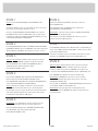
ÉTAPE 1
Ne pas serrer les EXCENTRIQUES ESCAMOTABLES dans
cette étape.
Assembler l'élément sur un sol à moquette ou sur le carton vide
pour éviter d'endommager l'élément ou le sol.
Enfoncer six EXCENTRIQUES ESCAMOTABLES (1F) dans les
EXTRÉMITÉS (A3 et B3) et le MONTANT (C3). Ensuite, insérer
l'extrémité en métal de la CHEVILLE D'EXCENTRIQUE (2F) dans
chaque EXCENTRIQUE ESCAMOTABLE.
ÉTAPE 2
Fixer l'ÉLÉMENT DROITE (35DA) et l'ÉLÉMENT GAUCHE (35DB) à
l'EXTRÉMITÉ DROITE (A3) et au MONTANT (C3). Utiliser quatre VIS
TÊTE PLATE 8 mm DORÉES (3S) à travers les trous nº 1 et nº 3.
ÉTAPE 6
Insérer une GOUPILLE EN MÉTAL (1R) dans le chant du
PETIT ARRIÈRE (H3).
Fixer le DESSUS (E2) au MONTANT (C3). Serrer deux
EXCENTRIQUES ESCAMOTABLES.
REMARQUE : S'assurer de bien insérer la GOUPILLE EN MÉTAL
dans le trou dans le DESSUS (E2).
Faire tourner un CLIP DE CORDON (4P) dans le trou sur la
surface inférieure du DESSUS (E2).
ÉTAPE 7
Fixer l'EXTRÉMITÉ DROITE (A3) au DESSUS (E2) et au DESSOUS (F3).
Serrer deux CONNECTEURS ESCAMOTABLE et utiliser deux VIS TÊTE
PLATE 49 mm NOIRES (113S).
À l'aide d'un marteau, enfoncer six PATINS (12E) dans les chants
inférieurs des EXTRÉMITÉS (A3 et B3) et MONTANT (C3).
ÉTAPE 3
Attention: Ne pas relever l'élément dans sa position verticale
avant d'avoir fi xé l’ARRIÈRE. L'élément risque de s'e ondrer.
Fixer le MONTANT (C3) au DESSUS DE BUREAU (D3) et
au DESSOUS (F3). Utiliser quatre VIS TÊTE
PLATE 49 mm NOIRES (113S).
ÉTAPE 8
Attention: Ne pas relever l'élément dans sa position verticale
avant d'avoir fi xé l’ARRIÈRE. L'élément risque de s'e ondrer.
Courber le rabat vers le haut sur l’ARRIÈRE (I) et le placer sur
l'ouverture entre l’EXTRÉMITÉ DROITE (A3) et le MONTANT (C3).
Fixer l'ARRIÈRE (I) à l'élément à l'aide des CLOUS (1N).
REMARQUE : L’ARRIÈRE doit se trouver contre la surface
inférieure du DESSUS (E2). Ne pas enfoncer les clous dans
l’EXTRÉMITÉ DROITE (A3).
Fixer le rabat de l'ARRIÈRE (I) à l'EXTRÉMITÉ DROITE (A3). Utiliser
six VIS TÊTE LARGE 14 mm NOIRES (1S).
REMARQUE : Des lignes perforées ont été prévues pour
accéder facilement à l'ARRIÈRE. Découper avec précaution les
trous nécessaires.
ÉTAPE 4
Fixer le PETIT ARRIÈRE (H3) au DESSUS DE BUREAU (D3).
Utiliser deux VIS TÊTE PLATE 49 mm NOIRES (113S).
Fixer l'EXTRÉMITÉ GAUCHE (B3) au DESSUS DE BUREAU (D3).
Serrer deux EXCENTRIQUES ESCAMOTABLES.
Attention: Risque des dégâts ou blessures. Les Excentriques
Escamotables doivent être serrés à bloc. Les Excentriques
Escamotables que ne sont pas serrées à bloc peuvent desserrer
et les pièces peuvent séparer. Pour serrer à bloc, faire tourner
l'excentrique escamotable de 210 degrés.
ÉTAPE 5
REMARQUE : Il est préférable de donner quelques tours de
tournevis à chaque VIS avant de les serrer toutes à bloc.
Fixer le VOILE DE FOND (G3) à l'EXTRÉMITÉ GAUCHE (B3)
et au MONTANT (C3). Utiliser quatre VIS TÊTE
PLATE 49 mm NOIRES (113S).
411606www.sauder.com/service
Page 19

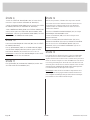
ÉTAPE 9
1 Insérer les CÔTÉS DE TIROIR (D20 et D21) en biseau dans la
fente dans chaque extrémité du DEVANT DE TIROIR (K2).
2 Enfi ler le FOND DE TIROIR (D951) dans les rainures des CÔTÉS
DE TIROIR (D20 et D21) et du DEVANT DE TIROIR (K2).
3 Fixer l'ARRIÈRE DE TIROIR (D148) aux CÔTÉS DE TIROIR (D20
et D21). Utiliser quatre VIS TÊTE PLATE 40 mm NOIRES (30S).
REMARQUE : S'assurer que le FOND DE TIROIR (D951) s'encastre
dans la rainure de l'ARRIÈRE DE TIROIR (D148).
ÉTAPE 10
Insérer une EXCENTRIQUE DE COULISSE (10A) dans les CÔTÉS
DE TIROIR (D20 et D21).
Fixer un TIROIR DROIT (35DC) et un TIROIR GAUCHE (35DD)
aux CÔTÉS DE TIROIR (D20 et D21). Utiliser quatre VIS TÊTE
PLATE 8 mm DORÉES (3S) à travers les trous nº 1 et nº 3.
REMARQUE : La tête de vis dans l'EXCENTRIQUE doit être visible
à travers le trou fendu dans la COULISSE.
ÉTAPE 12
Relever, avec précaution, l'élément dans sa position verticale.
Pour insérer le tiroir dans l'élément, abaisser le devant du tiroir
et faire passer les roulettes situées sur le tiroir derrière les
roulettes situées sur l'élément. Relever le devant du tiroir et
l'enfi ler dans l'élément.
Enfoncer un COUVERCLE D'EXCENTRIQUE (12P) sur chaque
EXCENTRIQUE ESCAMOTABLE visible.
Centrer un CACHE-VIS (20P) sur la tête de chaque VIS et
appuyer fermement.
Enfoncer les MANCHONS EN CAOUTCHOUC (2R) sur les
GOUPILLES EN MÉTAL (1R). Insérer les GOUPILLES EN MÉTAL
dans les trous choisis de l'EXTRÉMITÉ DROITE (A3) et du
MONTANT (C3). Poser la TABLETTE RÉGLABLE (J2) sur les
GOUPILLES EN MÉTAL.
ÉTAPE 13
Pour ajuster le tiroir, desserrer la VIS nº 3 dans les COULISSES
un quart de tour et tourner ensuite la CAME dans le sens des
aiguilles d'une montre ou dans le sens contraire. Noter que le tiroir
monte ou descend lorsque l'on tourne la CAME. Plus la vis dans le
trou oblong est haute, plus le devant de tiroir sera haut. Plus la vis
est basse, plus le devant de tiroir sera bas. Ajuster le tiroir de cette
manière permet au DEVANT DE TIROIR d'être mieux aligné une
fois fermé. Resserrer les VIS après d'avoir ajusté.
REMARQUE : Prière de lire les informations importantes sur la
sécurité fi gurant sur les pages arrière du manuel d’instructions.
Ceci complète l'assemblage. Nettoyer à l’aide d’une encaustique
pour meubles ou d’un chi on humide. Essuyer.
ÉTAPE 11
Fixer la POIGNÉE (1K) au DEVANT DE TIROIR (K2). Utiliser deux
VIS TÊTE PLATE 25 mm MARRON (12S).
411606 www.sauder.com/servicePage 20
La page est en cours de chargement...
La page est en cours de chargement...
La page est en cours de chargement...
La page est en cours de chargement...
La page est en cours de chargement...
La page est en cours de chargement...
La page est en cours de chargement...
La page est en cours de chargement...
-
 1
1
-
 2
2
-
 3
3
-
 4
4
-
 5
5
-
 6
6
-
 7
7
-
 8
8
-
 9
9
-
 10
10
-
 11
11
-
 12
12
-
 13
13
-
 14
14
-
 15
15
-
 16
16
-
 17
17
-
 18
18
-
 19
19
-
 20
20
-
 21
21
-
 22
22
-
 23
23
-
 24
24
-
 25
25
-
 26
26
-
 27
27
-
 28
28


dans d''autres langues
- English: Sauder 411606 Operating instructions
- español: Sauder 411606 Instrucciones de operación
Documents connexes
-
Sauder 413118 Mode d'emploi
-
-
-
-
-
-
-
-
-