
ˎ
ˎ
ˎ
VCT-55LH
XLR
WEB
ˎ
ˎ
ˎ
ˎ
ˎ
ˎ
ˎ
1 2 3
4 REC CH SELECT
INPUT1 5 ATT INPUT1
6 INPUT1
LINE/MIC/MIC+48V
7 ATT
INPUT2
8 INPUT2
LINE/MIC/MIC+48V
9 LOW CUT
INPUT1 10 AUTO/MAN CH1
11 AUDIO LEVEL
CH1
12 AUTO/MAN
CH2
13 AUDIO LEVEL
CH2
14 LOW CUT
INPUT2 15
/ Operating Instructions /
Mode d’emploi / Manual de
instrucciones /
XLR-K2M
XLR
XLR Adaptor Kit
Kit adaptateur XLR
© 2014 Sony Corporation Printed in Japan
4-546-775-
01
(1)
4
10 11 12 13 14
1
17
18
19
20 21
15
16
3
2
5 6 7 8 9
1
3
2
2
1
4
5
3
2
5
1
3
22
(Suite à la page arrière)
16 17
18
19 20 INPUT2
21 INPUT1
20 21
6 8
5 7
4
10 11 12 13
/ 9 14
XLR
1
XLR
2 XLR
3 XLR
ˎ
XLR
XLR
XLR
1
-1
2
3 ECM-XM1
4 XLR INPUT1
1 INPUT1
5 XLR
-19
ˎ
ˎ
-18
1 INPUT 1 LINE/MIC/MIC+48V
MIC+48V
2 REC CH SELECT INPUT1 CH1
CH2
CH1 CH2
CH1 CH1
INPUT1 /INPUT2
MIC
1 CH1 CH2 AUTO/
MAN
MAN
2 AUDIO LEVEL
AUTO/MAN AUTO
INPUT1 /INPUT2
LOW CUT INPUT1 LOW CUT
INPUT2 ON
1
INPUT1 /INPUT2
INPUT1/INPUT2
LINE/MIC/MIC+48V
LINE
MIC
+48V
MIC+48V
ˎ
MIC+48V +48V
ˎ
INPUT1/
INPUT2
LINE/MIC/MIC+48V LINE
2
INPUT1/INPUT2 LINE/MIC/MIC+48V MIC
MIC+48V ATT INPUT1/INPUT2
ECM-XM1 ATT 10dB
ATT 0dB -60dBu
ATT 10dB
-50dBu
ATT 20dB
-40dBu
ˎ
INPUT1/INPUT2 LINE/MIC/MIC+48V LINE
+4dBu ATT
3
REC CH SELECT INPUT1
REC CH SELECT
INPUT1 CH1 CH2
CH1 CH2
INPUT1
CH1
CH2
CH1
INPUT1
CH1
INPUT2
CH2
ˎ
XLR 3PIN 2
INPUT1 Lch INPUT2 Rch REC
CH SELECT
INPUT1 CH1
XLR XLR-A2M
116.5 mm 105.5 mm 75 mm
ECM-XM1
21 mm 162 mm
XLR XLR-A2M 250 g
ECM-XM1 121.5 g
0 40
-20 +60
INPUT1/INPUT2 XLR 3
MIC -60/-50/-40 dBu 3 k
LINE +4 dBu 10 k
0 dBu=0.775 Vrms
XLR XLR-A2M 1 ECM-XM1 1
1 1
1
ˎ
ˎ
ˎ
1
7
ˎ
XLR-K2M
ˎ
ˎ
Before operating the product, please read this manual
thoroughly and retain it for future reference.
WARNING
To reduce fire or shock hazard, do not expose the unit to
rain or moisture.
Keep out of reach of small children to prevent accidental
swallowing.
For the Customers in the U.S.A.
CAUTION
You are cautioned that any changes or modifications not
expressly approved in this manual could void your authority
to operate this equipment.
Note:
This equipment has been tested and found to comply
with the limits for a Class B digital device, pursuant to Part
15 of the FCC Rules. These limits are designed to provide
reasonable protection against harmful interference in a
residential installation. This equipment generates, uses,
and can radiate radio frequency energy and, if not installed
and used in accordance with the instructions, may cause
harmful interference to radio communications. However,
there is no guarantee that interference will not occur in a
particular installation. If this equipment does cause harmful
interference to radio or television reception, which can be
determined by turning the equipment o and on, the user
is encouraged to try to correct the interference by one or
more of the following measures:
—Reorient or relocate the receiving antenna.
—Increase the separation between the equipment and
receiver.
—Connect the equipment into an outlet on a circuit dierent
from that to which the receiver is connected.
—Consult the dealer or an experienced radio/TV technician
for help.
THIS DEVICE COMPLIES WITH PART 15 OF THE FCC
RULES. OPERATION IS SUBJECT TO THE FOLLOWING TWO
CONDITIONS:
(1) THIS DEVICE MAY NOT CAUSE HARMFUL INTERFERENCE,
AND (2) THIS DEVICE MUST ACCEPT ANY INTERFERENCE
RECEIVED, INCLUDING INTERFERENCE THAT MAY CAUSE
UNDESIRED OPERATION.
For the Customers in Europe
Disposal of Old Electrical & Electronic
Equipment (Applicable in the European
Union and other European countries with
separate collection systems)
This symbol on the product or on its
packaging indicates that this product
shall not be treated as household waste.
Instead it shall be handed over to the
applicable collection point for the recycling of electrical
and electronic equipment. By ensuring this product is
disposed of correctly, you will help prevent potential
negative consequences for the environment and human
health, which could otherwise be caused by inappropriate
waste handling of this product. The recycling of materials
will help to conserve natural resources. For more detailed
information about recycling of this product, please contact
your local Civic Oce, your household waste disposal
service or the shop where you purchased the product.
< Notice for the customers in the
countries applying EU Directives >
Manufacturer: Sony Corporation, 1-7-1 Konan Minato-ku
Tokyo, 108-0075 Japan
For EU product compliance: Sony Deutschland GmbH,
Hedelfinger Strasse 61, 70327 Stuttgart, Germany
Features
The XLR-K2M is a kit including an XLR Adaptor for a device
equipped with a Multi Interface Shoe and a microphone.
Some camera models with a Multi Interface Shoe cannot be
used with this kit.
For details on compatible camera models of this unit, visit
the website of Sony in your area, or consult your dealer of
Sony or local authorized Sony service facility.
Notes on use
• The microphone is a precision instrument. Do not drop,
knock it, or subject it to excessive shock.
• If the microphone is placed near speakers, a howling
eect (acoustic feedback) may occur. If this happens,
place the microphone as far as possible from the
speakers, or lower the volume of the speaker.
• Do not hold this unit to pick up or carry the camera when
attached.
• To carry this unit, remove it from the camera, attach
the connector protect cap to this unit and put it in the
supplied carrying case.
Notes on changing the lens
• Before changing the lens, remove this unit from the
camera.
• Before changing the lens, check whether there are any
fibers from the wind screen on the lens or camera body.
Brush any fibers o with a blower etc. and then change
the lens.
• After using this unit, cleaning the lens is recommended.
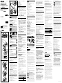
Identifying the parts
1 Wind screen 2 Microphone 3 Microphone holder
4 REC CH SELECT (INPUT1) switch 5 ATT (INPUT1) switch
6 INPUT1 (LINE/MIC/MIC+48V) switch 7 ATT (INPUT2) switch
8 INPUT2 (LINE/MIC/MIC+48V) switch
9 LOW CUT (INPUT1) switch 10 AUTO/MAN (CH1) switch
11 AUDIO LEVEL (CH1) dial 12 AUTO/MAN (CH2) switch
13 AUDIO LEVEL (CH2) dial 14 LOW CUT (INPUT2) switch
15 Lock dial 16 Multi Interface foot
17 Connector protect cap 18 Release lever 19 Cable holder
20 INPUT2 jack 21 INPUT1 jack
Inputting external sound: 20, 21
Selecting a sound source: 6, 8
Selecting a sound source level: 5, 7
Selecting channel setting for recording: 4
Selecting the recording level: 10, 11, 12, 13
Switching wind noise reduction to ON/OFF: 9, 14
Attaching the XLR Adaptor
1 Detach the connector protect cap from
the connector plug of the XLR Adaptor.
Check that the lock pin is not protruding from the bottom
of the Multi Interface foot of the XLR Adaptor.
2 Attach the Multi Interface foot of the XLR
Adaptor to the Multi Interface Shoe of
the camera.
3 Tighten the lock dial of the XLR Adaptor
securely.
Notes
• Insert the Multi Interface foot of the XLR Adaptor fully into
the Multi Interface Shoe of the camera, and tighten the
lock dial securely. Make sure this unit is attached securely.
When detaching the XLR Adaptor
Fully loosen the lock dial of the XLR Adaptor before
detaching the XLR Adaptor.
Attaching the microphone
1 Attach the wind screen (-1) to the
microphone.
2 Unlock the stopper of the microphone
holder and open the cover.
3 Place the microphone into the holder so
that the model name (ECM-XM1) on the
microphone faces upward. Then close the
cover and firmly lock the stopper.
4 Connect the connector plug of the
microphone to the INPUT1 jack on the
XLR Adaptor.
Connect the connector plug of the microphone to the
INPUT1 jack if you connect one device.
5 Put the microphone cable into the cable
holder (-19) on the XLR Adaptor.
• See “Audio setup” for audio recording.
• If the cable is pulled with too much force or attached to
the cable holder too loosely, the microphone attached
to the microphone holder may tilt a lot.
To get the full anti-vibration eect, make sure the
microphone is not tilting too much.
When detaching the microphone cable
Detach the microphone from the microphone holder.
Unplug the microphone plug while pressing the release
lever (-18) down.
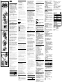
Audio setup
Using the supplied microphone
You can record unidirectional monaural sound with the
microphone.
1 Set the INPUT1 (LINE/MIC/MIC+48V)
switch to MIC+48V.
2 Set the REC CH SELECT (INPUT1) switch to
CH1·CH2.
This setting enables recording on both CH1 and CH2. Set
the switch to CH1 if you want to record on CH1 only.
Adjusting the recording level
You can adjust the recording level input from the INPUT1/
INPUT2 jacks.
You cannot adjust the recording level of the internal
microphone and MIC input jack.
1 Set the AUTO/MAN (CH1/CH2) switch of
the channel to be adjusted to MAN.
2 Turn the AUDIO LEVEL dial to adjust the
volume to the proper level.
Check that the volume is at the proper level, with
headphones or audio level meter.
To restore automatic adjustment
Set the AUTO/MAN (CH1/CH2) switch to AUTO.
Reducing wind noise
You can reduce wind noise input from the INPUT1/INPUT2
jacks.
Set the LOW CUT (INPUT1) switch or LOW
CUT (INPUT2) switch to ON.
Using an external audio device
Set as follows when you use a microphone other than the
supplied microphone or an external audio device (mixer,
etc.).
1 Select the sound source to be input.
Set the INPUT1/INPUT2 (LINE/MIC/MIC+48V) switch
according to the device to be connected to the INPUT1/
INPUT2 jacks.
External audio device (mixer, etc.): LINE
Dynamic microphone or microphone with built-in
battery: MIC
Microphone that is 48V phantom power compliant:
MIC+48V
Notes
• If you connect a device that does not support 48V
phantom power, malfunction may result from setting
this switch to MIC+48V. Check before connecting the
device.
• If noise from the unused jack bothers you, set the
INPUT1/INPUT2 (LINE/MIC/MIC+48V) switch of the
unused jack to LINE.
2 Set the input level of the microphone.
When the INPUT1/INPUT2 (LINE/MIC/MIC+48V) switch is
set to MIC or MIC+48V, you can set the input level with
the ATT (INPUT1/INPUT2) switch.
Adjust according to the microphone sensitivity.
ATT 10dB is recommended when you use the supplied
microphone (ECM-XM1).
The input levels are as follows.
ATT 0dB: -60dBu
ATT 10dB: -50dBu
ATT 20dB: -40dBu
Notes
• When the INPUT1/INPUT2 (LINE/MIC/MIC+48V) switch
is set to LINE, the input level is fixed to +4dBu. Even
if you reset the ATT switch, the input level does not
change.
3 Set the channel to be recorded.
You can select the channel to be recorded, with the REC
CH SELECT (INPUT1) switch.
Position of the REC
CH SELECT (INPUT1)
switch
Audio recorded on CH1 & CH2
CH1·CH2
INPUT1
CH1
CH2
CH1
INPUT1
CH1
INPUT2
CH2
• To use a stereo microphone with two XLR (3PIN) plugs,
connect Lch to the INPUT1 jack and Rch to the INPUT2
jack, and set the REC CH SELECT (INPUT1) switch to
CH1.
Specifications
Maximum dimensions (Approx.)
XLR Adaptor (XLR-A2M) unit
116.5 mm × 105.5 mm × 75 mm (w/h/d)
(4 5/8 in. × 4 1/4 in. × 3 in.)
(excluding the cord and projecting parts)
Microphone (ECM-XM1)
21 mm × 162 mm (Diameter/Length)
(27/32 in. × 61/2in.)
(excluding the wind screen and cord)
Mass (Approx.)
XLR Adaptor (XLR-A2M) unit 250 g (8 oz)
Microphone (ECM-XM1) 121.5 g (4 oz)
Operating temperature 0 °C to 40 °C (32 °F to 104 °F)
Storage temperature -20 °C to +60 °C (-4 °F to +140 °F)
Input jacks
INPUT1/INPUT2 jacks: XLR3-pin, female
MIC: -60 dBu /-50 dBu /-40 dBu, 3 kΩ(kilohms)
LINE: +4 dBu, 10 kΩ (kilohms)
(0 dBu=0.775 Vrms)
Included items
XLR Adaptor (XLR-A2M) (1), Microphone (ECM-XM1) (1),
Wind screen (1), Connector protect cap(1), Carrying case
(1), Set of printed documentation
Design and specifications are subject to change without
notice.
Multi Interface Shoe is a trademark of Sony Corporation.
Avant d’utiliser ce produit, prière de lire attentivement ce
mode d’emploi et de le conserver pour toute référence
future.
AVERTISSEMENT
Afin de réduire les risques d’incendie ou de décharge
électrique, n’exposez pas cet appareil à la pluie ou à
l’humidité.
Rangez hors de portée des enfants pour éviter toute
ingestion accidentelle.
À l’intention des clients aux É.-U.
AVERTISSEMENT
Par la présente, vous êtes avisé du fait que tout
changement ou toute modification ne faisant pas l’objet
d’une autorisation expresse dans le présent manuel
pourrait annuler votre droit d’utiliser l’appareil.
Note
L’appareil a été testé et est conforme aux exigences d’un
appareil numérique de Classe B, conformément à la Partie
15 de la réglementation de la FCC.
Ces critères sont conçus pour fournir une protection
raisonnable contre les interférences nuisibles dans un
environnement résidentiel. L’appareil génère, utilise et peut
émettre des fréquences radio; s’il n’est pas installé et utilisé
conformément aux instructions, il pourrait provoquer des
interférences nuisibles aux communications radio.
Cependant, il n’est pas possible de garantir que des
interférences ne seront pas provoquées dans certaines
conditions particulières. Si l’appareil devait provoquer des
interférences nuisibles à la réception radio ou à la télévision,
ce qui peut être démontré en allumant et éteignant
l’appareil, il est recommandé à l’utilisateur d’essayer de
corriger cette situation par l’une ou l’autre des mesures
suivantes :
—Réorienter ou déplacer l’antenne réceptrice.
—Augmenter la distance entre l’appareil et le récepteur.
—Brancher l’appareil dans une prise ou sur un circuit
diérent de celui sur lequel le récepteur est branché.
—Consulter le détaillant ou un technicien expérimenté en
radio/téléviseurs.
Cet appareil est conforme à la section 15 des règlements
FCC. Son fonctionnement est soumis aux deux conditions
suivantes : (1) cet appareil ne doit pas provoquer
d’interférences nuisibles, (2) cet appareil doit accepter toute
interférence, y compris celles susceptibles de provoquer son
fonctionnement indésirable.
Pour les clients en Europe
Traitement des appareils électriques et
électroniques en fin de vie (Applicable
dans les pays de l’Union Européenne et
aux autres pays européens disposant de
systèmes de collecte sélective)
Ce symbole, apposé sur le produit ou sur son
emballage, indique que ce produit ne doit
pas être traité avec les déchets ménagers.
Il doit être remis à un point de collecte
approprié pour le recyclage des équipements électriques et
électroniques. En vous assurant que ce produit sont mis au
rebut de façon appropriée, vous participez activement à la
prévention des conséquences négatives que leur mauvais
traitement pourrait provoquer sur l’environnement et sur la
santé humaine. Le recyclage des matériaux contribue par
ailleurs à la préservation des ressources naturelles. Pour
toute information complémentaire au sujet du recyclage de
ce produit, vous pouvez contacter votre municipalité, votre
déchetterie locale ou le point de vente où vous avez acheté
le produit.
< Avis aux consommateurs des pays
appliquant les Directives UE >
Fabricant: Sony Corporation, 1-7-1 Konan Minato-ku Tokyo,
108-0075 Japon
Pour toute question relative à la conformité des produits
dans l’UE: Sony Deutschland GmbH, Hedelfinger Strasse 61,
70327 Stuttgart, Allemagne
Caractéristiques
Le XLR-K2M est un kit comprenant un adaptateur XLR pour
appareil à grie multi-interface et un microphone.
Certains modèles d’appareils photo/caméscopes à grie
multi-interface ne peuvent pas être utilisés avec ce kit.
Pour plus de détails sur les modèles d’appareils photo/
caméscopes compatibles avec cet accessoire, consultez le
site Web de Sony de votre région, ou adressez-vous à votre
revendeur Sony ou au service après-vente agréé Sony local.
Remarques sur l’emploi
• Le microphone est un instrument de précision. Ne le
laissez pas tomber, ne le cognez pas et ne le soumettez
pas à des chocs.
• Si le microphone est placé près d’enceintes, un hurlement
(rétroaction acoustique) peut se produire. Dans ce cas,
éloignez le plus possible le microphone des enceintes, ou
bien réduisez le volume du microphone.
• Ne soulevez pas ou ne tenez pas l’appareil photo/
caméscope par cet accessoire lorsque ce dernier est
rattaché.
• Pour transporter cet accessoire, retirez-le de l’appareil
photo/caméscope, rattachez le capuchon de protection
de connecteur et rangez-le dans l’étui de transport fourni.
Remarques sur le changement d’objectif
• Avant de changer d’objectif, retirez cet accessoire de
l’appareil photo/caméscope.
• Avant de changer d’objectif, assurez-vous de l’absence de
fibres de la bonnette antivent sur l’objectif ou l’appareil
photo/caméscope. Retirez toute fibre avec un souet, etc.
avant de changer d’objectif.
• Il est conseillé de nettoyer l’objectif après l’utilisation de
cet accessoire.
Identification des éléments
1 Bonnette antivent 2 Microphone
3 Support de microphone
4 Commutateur REC CH SELECT (INPUT1)
5 Commutateur ATT (INPUT1)
6 Commutateur INPUT1 (LINE/MIC/MIC+48V)
7 Commutateur ATT (INPUT2)
8 Commutateur INPUT2 (LINE/MIC/MIC+48V)
9 Commutateur LOW CUT (INPUT1)
10 Commutateur AUTO/MAN (CH1)
11 Molette AUDIO LEVEL (CH1)
12 Commutateur AUTO/MAN (CH2)
13 Molette AUDIO LEVEL (CH2)
14 Commutateur LOW CUT (INPUT2)
15 Molette de verrouillage 16 Sabot multi-interface
17 Capuchon de protection de connecteur
18 Levier de libération 19 Support de câble
20 Prise d’entrée INPUT2 21 Prise d’entrée INPUT1
Transmission d’un son externe: 20, 21
Sélection d’une source sonore: 6, 8
Sélection du niveau d’une source sonore: 5, 7
Sélection d’un canal pour l’enregistrement: 4
Sélection du niveau d’enregistrement: 10, 11, 12, 13
Activation/désactivation de la réduction du bruit du
vent: 9, 14
Fixation de l’adaptateur
XLR
1 Détachez le capuchon de protection de
connecteur de la fiche-connecteur de
l’adaptateur XLR.
Assurez-vous que la goupille de verrouillage ne dépasse
pas de la partie inférieure du sabot multi-interface de
l'adaptateur XLR.
2 Raccordez le sabot multi-interface
de l’adaptateur XLR à la grie multi-
interface de l’appareil photo/caméscope.
3 Serrez correctement la molette de
verrouillage de l’adaptateur XLR.
Remarques
• Insérez à fond le sabot multi-interface de l’adaptateur
XLR dans la grie multi-interface de l’appareil photo/
caméscope, puis serrez la molette de verrouillage.
Assurez-vous que cet accessoire est bien rattaché.
Pour détacher l’adaptateur XLR
Desserrez complètement la molette de verrouillage de
l’adaptateur XLR avant de détacher l’adaptateur XLR.

(Suite de la page avant)
4
10 11 12 13 14
1
17
18
19
20 21
15
16
3
2
5 6 7 8 9
1
3
2
2
1
3
22
1
4
5
3
2
5
Fixation du microphone
1 Rattachez la bonnette antivent (-1) au
microphone.
2 Débloquez la fermeture du support de
microphone et ouvrez le couvercle.
3 Placez le microphone sur le support de
telle manière que le nom de modèle
(ECM-XM1) du microphone soit orienté
vers le haut. Fermez ensuite le couvercle
et bloquez bien la fermeture.
4 Raccordez la fiche-connecteur du
microphone à la prise INPUT1 de
l’adaptateur XLR.
Raccordez la fiche-connecteur du microphone à la prise
INPUT1 si vous raccordez un appareil.
5 Mettez le câble de microphone dans le
support de câble (-19) sur l’adaptateur
XLR.
• Voir « Réglage du son » pour l’enregistrement du son.
• Si une force excessive est appliquée sur le câble ou si le
câble est trop lâche sur son support, le microphone fixé
au support risque de s’incliner fortement.
Pour obtenir un eet antivibrations total, assurez-vous
que le microphone n’est pas trop incliné.
Lorsque le câble de microphone est
détaché
Détachez le microphone du support de microphone.
Débranchez la fiche de microphone tout en appuyant sur
le levier de libération (-18).
Réglage du son
Utilisation du microphone fourni
Vous pouvez enregistrer le son en monophonie
unidirectionnel avec le microphone.
1 Réglez le commutateur INPUT1 (LINE/
MIC/MIC+48V) sur MIC+48V.
2 Réglez le commutateur REC CH SELECT
(INPUT1) sur CH1·CH2.
Ce réglage permet d’enregistrer sur les deux canaux CH1
et CH2. Réglez le commutateur sur CH1 si vous voulez
enregistrer sur CH1 seulement.
Réglage du niveau d’enregistrement
Vous pouvez régler le niveau d’enregistrement du son
provenant des prises INPUT1/INPUT2.
Vous ne pouvez pas régler le niveau d’enregistrement du
microphone interne et de la prise d’entrée MIC.
1 Réglez le commutateur AUTO/MAN (CH1/
CH2) du canal devant être ajusté sur
MAN.
2 Tournez la molette AUDIO LEVEL pour
ajuster le volume au niveau souhaité.
Assurez-vous que le volume est au niveau correct avec
un casque d’écoute ou un indicateur de niveau sonore.
Pour revenir au réglage automatique
Réglez le commutateur AUTO/MAN (CH1/CH2) sur AUTO.
Réduction du bruit du vent
Vous pouvez réduire le bruit du vent provenant des prises
INPUT1/INPUT2.
Réglez le commutateur LOW CUT (INPUT1)
ou le commutateur LOW CUT (INPUT2) sur
ON.
Utilisation d’un appareil audio externe
Faites les réglages suivants lorsque vous utilisez un
microphone autre que le microphone fourni ou un appareil
audio externe (mixeur, etc.).
1 Sélectionnez la source sonore à
transmettre.
Réglez le commutateur INPUT1/INPUT2 (LINE/MIC/
MIC+48V) selon l’appareil devant être branché sur les
prises INPUT1/INPUT2.
Appareil audio externe (mixeur, etc.) : LINE
Microphone dynamique ou microphone avec pile
intégrée : MIC
Microphone compatible ayant une alimentation fantôme
de 48 V : MIC+48V
Remarques
• Si vous raccordez un appareil ne prenant pas en
charge une alimentation fantôme de 48V, le réglage
de ce commutateur sur MIC+48V peut entraîner
un dysfonctionnement. Vérifiez avant de raccorder
l’appareil.
• Si le bruit émis par la prise non utilisée vous dérange,
réglez le commutateur INPUT1/INPUT2 (LINE/MIC/
MIC+48V) de la prise non utilisée sur LINE.
2 Réglez le niveau d’entrée du microphone.
Lorsque le commutateur INPUT1/INPUT2 (LINE/MIC/
MIC+48V) est réglé sur MIC ou MIC+48V, vous pouvez
régler le niveau d’entrée avec le commutateur ATT
(INPUT1/INPUT2).
Réglez-le en fonction de la sensibilité du microphone.
ATT 10dB est recommandé lorsque vous utilisez le
microphone fourni (ECM-XM1).
Les niveaux d’entrée sont les suivants.
ATT 0dB : -60 dBu
ATT 10dB : -50 dBu
ATT 20dB : -40 dBu
Remarques
• Lorsque le commutateur INPUT1/INPUT2 (LINE/MIC/
MIC+48V) est réglé sur LINE, le niveau d’entrée reste
fixé sur +4dBu. Même si le commutateur ATT est
réinitialisé, le niveau d’entrée ne change pas.
3 Réglez le canal à enregistrer.
Vous pouvez sélectionner le canal à enregistrer avec le
commutateur REC CH SELECT (INPUT1).
Position du
commutateur REC
CH SELECT (INPUT1)
Son enregistré sur CH1 & CH2
CH1·CH2
INPUT1
CH1
CH2
CH1
INPUT1
CH1
INPUT2
CH2
• Pour utiliser un microphone stéréo avec deux fiches
XLR (3PIN), raccordez le canal gauche à la prise
INPUT1 et le canal droit à la prise INPUT2, et réglez le
commutateur REC CH SELECT (INPUT1) sur CH1.
Spécifications
Dimensions (environ)
Adaptateur XLR (XLR-A2M)
116,5 mm × 105,5 mm × 75 mm (l/h/p)
(4 5/8 po. × 4 1/4 po. × 3 po.)
(cordon et parties saillantes non compris)
Microphone (ECM-XM1)
21 mm × 162 mm (diamètre/longueur)
(27/32 po. × 61/2 po.)
(bonnette antivent et cordon non compris)
Poids (environ)
Adaptateur XLR (XLR-A2M) 250 g (8 oz)
Microphone (ECM-XM1) 121,5 g (4 oz)
Température de fonctionnement
0 °C à 40 °C (32 °F à 104 °F)
Température d’entreposage
-20 °C à +60 °C (-4 °F à +140 °F)
Prises d’entrée
Prises INPUT1/INPUT2 : XLR 3 broches, femelle
MIC : -60 dBu /-50 dBu /-40 dBu, 3kΩ (kilohms)
LINE : +4 dBu, 10 kΩ (kilohms) (0dBu=0,775 ecace)
Articles inclus
Adaptateur XLR (XLR-A2M) (1), Microphone (ECM-XM1) (1),
Bonnette antivent (1), Capuchon de protection de
connecteur (1), Étui de transport (1), Jeu de documents
imprimés
La conception et les spécifications peuvent être modifiées
sans préavis.
Multi Interface Shoe est une marque commerciale de Sony
Corporation.
Antes de poner en funcionamiento el producto, lea
detalladamente todo este manual y guárdelo para poderlo
consultar en el futuro.
AVISO
Para reducir el riesgo de incendio o descarga eléctrica, no
exponga la unidad a la lluvia ni a la humedad.
Mantenga fuera del alcance de niños para evitar su tragado
accidental.
Para los clientes en Europa
Tratamiento de los equipos eléctricos y
electrónicos al final de su vida útil
(aplicable en la Unión Europea y en países
europeos con sistemas de tratamiento
selectivo de residuos)
Este símbolo en el equipo o en su embalaje
indica que el presente producto no puede
ser tratado como residuos doméstico normal.
Debe entregarse en el correspondiente
punto de recogida de equipos eléctricos y electrónicos.
Al asegurarse de que este producto se desecha
correctamente, usted ayuda a prevenir las consecuencias
potencialmente negativas para el medio ambiente y la
salud humana que podrían derivarse de la incorrecta
manipulación en el momento de deshacerse de este
producto. El reciclaje de materiales ayuda a conservar los
recursos naturales. Para recibir información detallada sobre
el reciclaje de este producto, póngase en contacto con
el ayuntamiento, el punto de recogida más cercano o el
establecimiento donde ha adquirido el producto.
< Aviso para los clientes de países en
los que se aplican las directivas de la
UE >
Fabricante: Sony Corporation, 1-7-1 Konan Minato-ku Tokyo,
108-0075 Japón
Para la conformidad del producto en la UE: Sony
Deutschland GmbH, Hedelfinger Strasse 61, 70327 Stuttgart,
Alemania
Características
El XLR-K2M es un juego que incluye un adaptador para XLR
para un dispositivo equipado con una zapata de interfaz
múltiple y un micrófono.
Algunos modelos de cámaras con zapata de interfaz
múltiple no pueden utilizarse con este juego.
Con respecto a los detalles sobre los modelos de cámaras
compatibles con esta unidad, visite el sitio Web de Sony de
su área, o póngase en contacto con su proveedor Sony o
con el centro de servicio local autorizado por Sony.
Notas sobre la utilización
• El micrófono es un instrumento de precisión. No lo deje
caer, golpee, ni lo someta a choques excesivos.
• Si coloca el micrófono cerca de altavoces, puede ocurrir
un efecto de aullido (retroalimentación acústica). Si
sucede esto, aleje el micrófono lo más posible de los
altavoces, o reduzca el volumen de dichos altavoces.
• No sujete esta unidad para tomar o transportar la cámara
cuando esté instalada.
• Para transportar esta unidad, retírela de la cámara, fíjele
la tapa protectora de conector, y colóquela en la funda de
transporte suministrada.
Nota sobre el cambio de objetivo
• Antes de cambiar el objetivo, extraiga esta unidad de la
cámara.
• Antes de cambiar el objetivo, compruebe que no haya
fibras del parabrisas en el objetivo o el cuerpo de la
cámara. Elimine las fibras que pueda haber con un
soplador, etc., y después cambie el objetivo.
• Después de utilizar esta unidad, se recomienda limpiar el
objetivo.
Identificación de los
componentes
1 Parabrisas 2 Micrófono 3 Soporte para micrófono
4 Selector REC CH SELECT (INPUT1) 5 Selector ATT (INPUT1)
6 Selector INPUT1 (LINE/MIC/MIC+48V)
7 Selector ATT (INPUT2)
8 Selector INPUT2 (LINE/MIC/MIC+48V)
9 Selector LOW CUT (INPUT1) 10 Selector AUTO/MAN (CH1)
11 Mando AUDIO LEVEL (CH1) 12 Selector AUTO/MAN (CH2)
13 Mando AUDIO LEVEL (CH2)
14 Selector LOW CUT (INPUT2) 15 Mando de bloqueo
16 Pata de interfaz múltiple 17 Tapa protectora de conector
18 Palanca de liberación 19 Soporte para cable
20 Toma INPUT2 21 Toma INPUT1
Aplicación de sonido externo: 20, 21
Selección de una fuente de sonido: 6, 8
Selección de un nivel de fuente de sonido: 5, 7
Selección de un ajuste de canal para grabación: 4
Selección del nivel de grabación: 10, 11, 12, 13
Activación/desactivación de la reducción de ruido de
viento: 9, 14
Fijación del adaptador para
XLR
1 Retire la tapa protectora de conector de
la clavija conectora del adaptador para
XLR.
Compruebe que el pasador de bloqueo no sobresalga
de la parte inferior de la pata de interfaz múltiple del
adaptador para XLR.
2 Fije la pata de interfaz múltiple del
adaptador para XLR a la zapata de
interfaz múltiple de la cámara.
3 Apriete con seguridad el mando de
bloqueo del adaptador para XLR.
Notas
• Inserte la pata de interfaz múltiple del adaptador para XLR
en la zapata de interfaz múltiple de la cámara, y después
apriete con seguridad el mando de bloqueo. Cerciórese
de que ésta haya quedado fijada con seguridad.
Cuando desmonte el adaptador para
XLR
Afloje completamente el mando de bloqueo del adaptador
para XLR antes de desmontar el adaptador para XLR.
Fijación del micrófono
1 Fije el parabrisas (-1) al micrófono.
2 Desbloquee el tope del soporte para
micrófono y abra la cubierta.
3 Coloque el micrófono en el soporte de
forma que el nombre del modelo (ECM-
XM1) del micrófono quede encarado
hacia arriba. Después cierre la cubierta y
bloquee firmemente el tope.
4 Conecte la clavija conectora del
micrófono en la toma INPUT1 del
adaptador para XLR.
Conecte la clavija conectora del micrófono en la toma
INPUT1 si va a conectar un dispositivo.
5 Ponga el cable del micrófono en el
soporte para cable (-19) del adaptador
para XLR.
• Consulte “Configuración de audio” para la grabación
de audio.
• Si tira con demasiada fuerza del cable o lo fija al
soporte del cable demasiado flojo, el micrófono fijado
al soporte del micrófono puede inclinarse mucho.
Para obtener el efecto de anti-vibración completo,
asegúrese de que el micrófono no esté demasiado
inclinando.
Cuando desmonte el cable del
micrófono
Desmonte el micrófono del soporte para micrófono.
Desconecte la clavija conector manteniendo presionada
la palanca de liberación (-18).
Configuración de audio
Utilización del micrófono suministrado
Con el micrófono puede grabar sonido monoaural
unidireccional.
1 Ponga el selector INPUT1 (LINE/MIC/
MIC+48V) en MIC+48V.
2 Ponga el selector REC CH SELECT (INPUT1)
en CH1·CH2.
Este ajuste permite grabar tanto en CH1 como en CH2.
Ponga el selector en CH1 si sólo desea grabar en CH1.
Ajuste del nivel de grabación
Puede ajustar el nivel de grabación de la entrada
procedente de las tomas INPUT1/INPUT2.
No puede ajustar el nivel de grabación del micrófono
interno ni de la toma de entrada MIC.
1 Ponga el selector AUTO/MAN (CH1/CH2)
del canal que desee ajustar en MAN.
2 Gire el mando AUDIO LEVEL para ajustar
el volumen al nivel apropiado.
Compruebe que el volumen esté al nivel apropiado con
los auriculares o el medidor de nivel de audio.
Para restablecer el ajuste automático
Ponga el selector AUTO/MAN (CH1/CH2) en AUTO.
Reducción del ruido de viento
Puede reducir el ruido de viento de la entrada procedente
de las tomas INPUT1/INPUT2.
Ponga el selector LOW CUT (INPUT1) o el
selector LOW CUT (INPUT2) en ON.
Utilización de un dispositivo de audio
externo
Ajuste de la forma siguiente cuando utilice un micrófono
que no sea el suministrado o un dispositivo de audio
externo (mezclador, etc.).
1 Seleccione la fuente de entrada que
desee aplicar.
Ajuste el selector INPUT1/INPUT2 (LINE/MIC/MIC+48V)
de acuerdo con el dispositivo que vaya a conectar a las
tomas INPUT1/INPUT2.
Dispositivo de audio externo (mezclador, etc.): LINE
Micrófono dinámico o micrófono con pila incorporada:
MIC
Micrófono que admite alimentación fantasma de 48 V:
MIC+48V
Notas
• Si conecta un dispositivo que no admite alimentación
fantasma de 48 V, puede resultar un mal
funcionamiento si pone este selector en MIC+48V.
Compruebe antes de conectar el dispositivo.
• Si el ruido procedente de la toma no utilizada le
molesta, ponga el selector INPUT1/INPUT2 (LINE/MIC/
MIC+48V) de la toma no utilizada en LINE.
2 Ajuste el nivel de entrada del micrófono.
Cuando el selector INPUT1/INPUT2 (LINE/MIC/MIC+48V)
esté ajustado a MIC o MIC+48V, podrá ajustar el nivel de
entrada con el selector ATT (INPUT1/INPUT2).
Ajuste de acuerdo con la sensibilidad del micrófono.
Se recomienda ATT 10dB cuando se utilice el micrófono
suministrado (ECM-XM1).
Los niveles de entrada son los siguientes.
ATT 0dB: -60dBu
ATT 10dB: -50dBu
ATT 20dB: -40dBu
Notas
• Cuando el selector INPUT1/INPUT2 (LINE/MIC/
MIC+48V) esté ajustado a LINE, el nivel de entrada
estará fijado a +4dBu. Aunque reponga el selector ATT,
el nivel de entrada no cambiará.
3 Ajuste el canal que desee grabar.
Puede seleccionar el canal que desee grabar con el
selector REC CH SELECT (INPUT1).
Posición del
selector REC CH
SELECT (INPUT1)
Audio grabado en CH1 y CH2
CH1·CH2
INPUT1
CH1
CH2
CH1
INPUT1
CH1
INPUT2
CH2
• Para utilizar un micrófono externo con dos clavijas
XLR (3 contactos), conecte el canal izquierdo a la toma
INPUT1 y el canal derecho a la toma INPUT2, y ajuste el
selector REC CH SELECT (INPUT1) a CH1.
Especificaciones
Dimensiones (Aprox.)
Unidad de adaptador para XLR (XLR-A2M)
116,5 mm × 105,5 mm × 75 mm (an/al/prf)
(excluyendo el cable y las partes salientes)
Micrófono (ECM-XM1)
21 mm × 162 mm (diámetro/longitud)
(excluyendo el parabrisas y el cable)
Peso (Aprox.)
Unidad de adaptador para XLR (XLR-A2M) 250 g
Micrófono (ECM-XM1) 121,5 g
Temperatura de funcionamiento 0 °C a 40 °C
Temperatura de almacenamiento -20 °C a +60 °C
Tomas de entrada
Tomas INPUT1/INPUT2: XLR, 3 contactos, hembra
MIC: -60 dBu /-50 dBu /-40 dBu, 3 kΩ (kiloohmios)
LINE: +4 dBu, 10 kΩ (kiloohmios) (0 dBu=0,775 Vrms)
Elementos incluidos
Adaptador para XLR (XLR-A2M) (1), Micrófono (ECM-XM1)
(1), Parabrisas (1), Tapa protectora de conector (1), Funda
de transporte (1), Juego de documentación impresa
El diseño y las especificaciones están sujetos a cambio sin
previo aviso.
Multi Interface Shoe es marca comercial de Sony
Corporation.
•
•
•
•
•
•
•
•
•
•
·
•
•
•
•
•
•
•
•
•
•
•
•
•
•
·
•
•
•
•
•
•
•
•
•
•
•
•
•
•
·
•
•
•
•
-
 1
1
-
 2
2


dans d''autres langues
- English: Sony XLR-K2M Operating instructions
- español: Sony XLR-K2M Instrucciones de operación
- 日本語: Sony XLR-K2M 取扱説明書
Documents connexes
-
Sony XLRK1M Manuel utilisateur
-
-
-
-
-
-
-
-
-