Sony XM-5150GSX Mode d'emploi
- Catégorie
- Amplificateurs audio
- Taper
- Mode d'emploi

10
0
-10
-20
-40
-50
-60
-70
-80
10 100 1k
-30
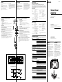
50Hz
LOW PASS
150Hz
300Hz
10
0
-10
-20
-30
100
-40
-50
-60
-70
-80
10 1k
HIGH PASS
50Hz
80Hz
150Hz
200Hz
300Hz
Sony Corporation 2002 Printed in China
XM-5150GSX
Specifications
AUDIO POWER SPECIFICATIONS
POWER OUTPUT AND TOTAL HARMONIC DISTORTION
40watts/150watts per channel minimum continuous average power into
4ohms, 5channels driven from 50Hz to 20kHz/20Hz to 300Hz (subwoofer)
with no more than 0.04% total harmonic distortion per Car Audio Ad Hoc
Committee Standards.
Other Specifications
Owner’s Record
The model and serial numbers are located on the bottom of the unit.
Record the serial number in the space provided below.
Refer to these numbers whenever you call upon your Sony dealer regarding this product.
Model No. XM-5150GSX Serial No.
3-239-441-11 (1)
Stereo Power
Amplifier
Operating Instructions
Mode d’emploi
Circuit system OTL (output transformerless) circuit
Pulse power supply
Inputs RCA pin jacks
Outputs Speaker terminals
Speaker impedance 2 – 8 Ω (stereo)
4 – 8 Ω (when used as a bridging
amplifier)
Maximum outputs 80 watts × 4 + 300 watts × 1 (at 4 Ω)
Rated outputs (supply voltage at 14.4 V)
5 Speakers: 40 watts × 4 (50 Hz – 20 kHz, 0.04 %
THD, at 4 Ω) + 150 watts × 1 (20 –
300 Hz, 0.04 % THD, at 4 Ω)
60 watts × 4 (50 Hz – 20 kHz, 0.1 %
THD, at 2 Ω) + 180 watts × 1 (20 –
300 Hz, 0.1 % THD, at 2 Ω)
3 Speakers: 120 watts × 2 (50 Hz – 20 kHz, 0.1 %
THD, at 4 Ω) + 150 watts × 1 (20 –
300 Hz, 0.04 % THD, at 4 Ω)
Frequency response 5 Hz – 50 kHz (
dB)
Harmonic distortion 0.005 % or less (at 1kHz, 4 Ω)
Input level adjustment range
0.2 – 6.0 V (RCA pin jacks)
High-pass filter 50 – 300 Hz, –12 dB/oct
Low-pass filter 50 – 300 Hz, –12 dB/oct
Power requirements 12 V DC car battery
(negative ground)
Power supply voltage 10.5 – 16 V
Current drain at rated output: 42 A
Remote input: 1.0 mA
Dimensions Approx. 14
1
/8 × 2 × 10
1
/2 in.
(w/h/d) (358 × 50 × 264 mm) not incl.
projecting parts and controls
Mass Approx. 3.5 kg (7 lb. 11 oz.) not incl.
accessories
Supplied accessories Mounting screws (4)
Design and specifications are subject to change without
notice.
Troubleshooting Guide
The following checklist will assist in the correction of most problems which you may encounter with your unit.
Before going through the checklist below, refer to the connection and operating procedures.
Guide de dépannage
La liste suivante vous aidera à résoudre la plupart des problèmes que vous pouvez rencontrer avec cet
appareil. Avant de passer la liste en revue, vérifiez les connexions et les procédures de fonctionnement.
Spécifications
Circuiterie Circuit OTL (Sortie sans
transformateur)
Entrées Prises à broche RCA
Sorties Bornes de haut-parleurs
Impédance des haut-parleurs
2 – 8 Ω (stéréo)
4 – 8 Ω (utilisé comme amplificateur
en pont)
Sorties maximales 80 watts × 4 + 300 watts × 1 (à 4 Ω)
Sorties nominales (tension d’alimentation de 14,4 V)
5 haut-parleurs: 40 watts × 4 (50 Hz – 20 kHz, 0,04 %
THD, à 4 Ω) + 150 watts × 1 (20 –
300 Hz, 0,04% THD, à 4 Ω)
60 watts × 4 (50 Hz – 20 kHz, 0,1 %
THD, à 2 Ω) + 180 watts × 1 (20 Hz –
300 Hz, 0,1 % THD, à 2 Ω)
3 haut-parleurs: 120 watts × 2 (50 Hz – 20 kHz, 0,1 %
THD, à 4 Ω) + 150 watts × 1 (20 –
300 Hz, 0,04% THD, à 4 Ω)
Réponse en fréquence 5 Hz – 50 kHz (
dB)
Distorsion harmonique 0,005 % ou inférieure (à 1kHz, 4 Ω)
Plage de réglage du niveau d'entrée
0,2 – 6,0 V (prises à broche RCA)
Filtre passe-haut 50 – 300 Hz, –12 dB/oct
Filtre passe-bas 50 – 300 Hz, –12 dB/oct
Alimentation Batterie de voiture, courant continu
12 V (masse négative)
Tension d'alimentation
10,5 – 16 V
Courant à la sortie nominale: 42 A
Entrée de télécommande: 1,0 mA
Dimensions Env. 14
1
/8 × 2 × 10
1
/2 po.
(l/h/p) (358 × 50 × 264 mm)
capuchon de protection de borne
compris
Poids Env. 3,5 kg (7 li. 11 on.) accessoires
non compris
Accessoires fournis Vis de montage (4)
La conception et les spécifications peuvent être modifiées
sans préavis.
Problem
The POWER indicator does not light
up.
The OVER CURRENT indicator lights
up in red.
The OFFSET indicator lights up in
red.
The THERMAL indicator lights up in
red.
Alternator noise is heard.
The sound is too low.
No sound is heard.
Cause/Solution
The fuse is blown. t Replace the fuse with a new one.
The ground lead is not securely connected. t Fasten the ground lead securely to
a metal surface of the car.
The voltage going into the remote terminal is too low.
•
The connected master unit is not turned on.
t
Turn on the master unit.
• The system employs too many amplifiers. t Use a relay.
Check the battery voltage (10.5 – 16 V).
Turn off the power switch. The speaker outputs are short-circuited. t Rectify
the cause of the short-circuit.
Turn off the power switch. Make sure the speaker cord and ground lead are
securely connected.
The unit heats up abnormally.
• Use speakers with suitable impedance.
• Make sure to place the unit in a well ventilated location.
The power connecting leads are installed too close to the RCA pin cords. t Keep
the power connecting leads away from the RCA pin cords.
The ground lead is not securely connected. t Fasten the ground lead securely to
a metal surface of the car.
Negative speaker leads are touching the car chassis. t Keep the leads away
from the car chassis.
The LEVEL adjustment control is set to the “MIN” position.
One or more of the switches is settled between settings (i.e., not correctly set); set
the switch properly.
Problème
L’indicateur POWER ne s’allume pas.
L’indicateur OVER CURRENT s’allume
en rouge.
L’indicateur OFFSET s’allume en
rouge.
L’indicateur THERMAL s’allume en
rouge.
L’alternateur émet un bruit.
Le son est trop faible.
Aucun son n’est audible.
Cause/Solution
Le fusible est grillé. t Remplacez le fusible par un neuf.
Le fil de masse n’est pas connecté correctement. t Fixez correctement le fil de
masse à un point métallique de la voiture.
La tension entrant à la borne de télécommande est trop faible.
• L’appareil maître connecté n’est pas allumé. t Mettez l’appareil maître sous
tension.
• Le système utilise trop d’amplificateurs. t Utilisez un relais.
Vérifiez la tension de la batterie (10,5 – 16 V).
Coupez l’interrupteur d’alimentation. Les sorties de haut-parleur sont court-
circuitées. t Remédiez à la cause du court-circuit.
Coupez l’interrupteur d’alimentation. Assurez-vous que le cordon de haut-
parleur et le fil de masse sont correctement branchés.
L’appareil chauffe anormalement.
• Utilisez des haut-parleurs d’une impédance appropriée.
• Installez l’appareil dans un endroit bien aéré.
Les câbles d’alimentation sont installés trop près des câbles à broches RCA.
t Eloignez les câbles d’alimentation des broches RCA.
Le fil de masse n’est pas connecté correctement. t Fixez correctement le fil de
masse à un point métallique de la voiture.
Les fils négatifs des haut-parleurs touchent la carrosserie de la voiture.
t Eloignez les fils de la carrosserie de la voiture.
La commande de réglage de niveau est mise en position “MIN”.
Un ou plusieurs commutateurs doivent être réglés entre deux positions de
réglage (c.-à-d., mal réglés); réglez correctement les commutateurs.
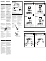
Location and Function of Controls
1 POWER indicator
Lights up in green during normal operation.
2 PROTECTOR indicator
• OVER CURRENT:
Lights up in red when input signal overload.
• OFFSET:
Lights up in red when the voltage going out to the Speaker terminal or the
Pin Jack is too high.
•THERMAL:
Lights up in red when the temperature rises to an unsafe level.
3 TEST TONE button
When the button is pressed, if the test tone can be heard from the connected
speakers, operation is normal.
46 Cut-off frequency adjustment control
Sets the cut-off frequency (50–300 Hz) for the high-pass or low-pass filters.
5 LEVEL adjustment control
The input level can be adjusted with this control. Turn it toward MAX when
the output level of the car audio seems low. To reduce noise, turn the LEVEL
control (gain) of the amplifer to MIN and the volume of the car audio up.
7 INPUT MODE select switch
When no input lead is connected to SUBWOOFER INPUT, the switch can be used to
change the SUBWOOFER OUTPUT as follows.
F : Outputs the signal that has been input to the FRONT input jack.
F+R : Outputs the signal that has been input to the FRONT and REAR input jacks.
8 SUBWOOFER LEVEL adjustment control
The input level can be adjusted with this control when using source equipment
made by other manufacturers. Turn it to MAX when the output level of the car
audio seems low. To reduce noise, turn the LEVEL control (gain) of the
amplifer to MIN and the volume of the car audio up.
Emplacement et fonction des commandes
1 Indicateur POWER
S’allume en vert en cours de fonctionnement normal.
2 Indicateur PROTECTOR
• OVER CURRENT:
S’allume en rouge lorsque le signal d’entrée est surchargé.
• OFFSET:
S’allume en rouge lorsque la tension de sortie vers le terminal du haut-
parleur ou la prise à broches est trop élevée.
• THERMAL:
S’allume en rouge lorsque la température atteint un niveau trop dangereux.
3 Touche TEST TONE
Si, lorsque vous appuyez sur cette touche, vous entendez la tonalité de test
depuis les enceintes raccordées, cela signifie que le fonctionnement est normal.
46 Commandes de réglage de la fréquence de coupure
Règle la fréquence de coupure (50-300 Hz) pour les filtres passe-bas ou
passe-haut.
5 Commande de réglage LEVEL
Le niveau d’entrée peut se régler avec cette commande. Tournez vers MAX
lorsque le niveau de sortie de l’xinstallation radio paraît faible. Mettez-le sur
MAX lorsque le niveau de sortie de l’installation audio paraît faible. Pour
réduire les parasites, tournez la commande LEVEL (gain) de l’amplificateur sur
MIN et augmentez le volume sur l’autoradio.
7 Sélecteur INPUT MODE
Si aucun fil d’entrée n’est raccordé à SUBWOOFER INPUT, le sélecteur peut
être utilisé pour changer SUBWOOFER OUTPUT comme suit.
F: Sortie du signal entré via la prise d’entrée FRONT.
F+R: Sortie du signal entré via les prises d’entrée FRONT et REAR.
8 Commande de réglage SUBWOOFER LEVEL (NIVEAU DE l’ENCEINTE D’EXTREMES
GRAVES)
Le niveau d’entrée peut se régler avec cette commande lors de l’utilisation
d’équipements source d’autres fabricants. Mettez-le sur MAX lorsque le niveau de
sortie de l’installation audio paraît faible. Pour réduire les parasites, tournez la
commande LEVEL (gain) de l’amplificateur sur MIN et augmentez le volume sur
l’autoradio.
* Pulse power supply
This unit has a built-in power regulator which converts the
power supplied by the DC 12 V car battery into high speed
pulses using a semiconductor switch. These pulses are
stepped up by the built-in pulse transformer and separated
into both positive and negative power supplies before being
converted into direct current again. This light weight power
supply system provides a highly efficient power supply with
a low impedance output.
Features
• Maximum power output of 80 watts × 4 + 300 watts
(at 4 ohms).
• Features a 2 channel-input / 5 channel-output
function that makes it possible to carry a 2-way
multi system even with a single line output from
the car stereo.
•
Low-pass filter, high-pass filter circuit are built-
in.
• Protection circuit and indicator provided.
• Pulse power supply* for stable, regulated output
power.
Caractéristiques
• Puissance de sortie maximale de 80 watts × 4 + 300
watts (à 4 ohms).
• Intègre une fonction d’entrée à 2 canaux/sortie à 5
canaux compatible avec un multisystème à 2 voies
même avec une sortie de ligne signal via la stéréo.
• Un circuit de filtre passe-bas et de filtre passe-haut
sont intégrés.
• Circuit de protection fourni.
• Alimentation électrique par impulsions* pour une
puissance de sortie stable, régulée.
* Alimentation électrique par impulsions
Cet appareil est équipé d’un régulateur de puissance intégré
qui convertit la puissance fournie par une batterie de
voiture de 12 V CC en impulsions ultra-rapides au moyen
d’un commutateur à semi-conducteur. Ces impulsions sont
amplifiées par le transformateur d’impulsions intégré et
séparées en alimentation positive et négative avant d’être
reconverties en courant continu. Ce système d’alimentation
de faible poids assure une alimentation électrique très
efficace pour une sortie d’impédance faible.
FREQUENCY Hz
Installation
Before Installation
• Mount the unit either inside the trunk or under a
seat.
• Choose the mounting location carefully so that the
unit will not interfere with the normal movements
of the driver and so it will not be exposed to direct
sunlight or hot air from the heater.
• Do not install the unit under the floor carpet, where
the heat dissipation from the unit will be
considerably impaired.
First, place the unit where you plan to install it, and
mark the positions of the four screw holes on the
surface of the mounting board (not supplied). Then
drill the holes approximately
1
/8 inches (in.)
(3 millimeters (mm)) in diameter and mount the unit
onto the board with the supplied mounting screws.
The supplied mounting screws are
19
/32 in. (15 mm)
long, therefore, make sure that the mounting board is
thicker than
19
/32 in. (15 mm).
Installation
Avant l'installation
• Installez l’appareil dans le coffre ou sous un siège.
• Choisissez soigneusement l’emplacement de
montage de façon à ce que l’appareil ne gêne pas les
mouvements normaux du conducteur et ne soit pas
exposé au rayonnement direct du soleil ni aux
conduits de chauffage.
• N’installez pas l’appareil sous le tapis de sol car la
dissipation thermique ne pourrait pas se faire
correctement.
Présentez d’abord l’appareil à l’endroit où vous
voulez l’installer et tracez un repère de
positionnement pour les quatre vis sur la plaque de
montage (non fournie). Percez des trous d’environ
1
/8 pouces (po.) (3 millimètres (mm)) de diamètre,
puis fixez l’appareil à l’aide des vis fournies. Celles-ci
font
19
/32 po. (15 mm) de long; vérifiez, par
conséquent, que la plaque fait au moins
19
/32 po.
(15 mm) d’épaisseur.
Circuit Diagram/Schéma du circuit
Unit : in. (mm)
Unitè : po. (mm)
ø
1
/4 (6)
9
1
/
4
(234)
14
1
/8 (358)
12
1
/4 (310)
10
1
/
2
(264)
2 (50)
POWER/PROTECTOR
OVER CURRENTPOWER OFFSET THERMAL
REAR
HPF
FRONT
LEVEL
TEST
TONE
MIN MAX50Hz 300Hz
HPF
LEVEL
MIN MAX50Hz 300Hz
345
SUB WOOFER
50Hz 300Hz
FF + R
LEVELMODE
LPF
MIN MAX
6
78
FREQUENCY Hz
Cut-off frequency/Fréquence de coupure
Buffer
AMP
Power
Lch
LEVEL
AMP
Power
Lch
FRONT
REAR
HPF
Rch
Rch
Buffer
SUB W.
Buffer
LEVEL
AMP
Power
SUB W.
LEVEL
FRONT
F+R
INPUT
MODE
HPF
LPF
dB dB

F
+
RF
MODE
F
+
RF
MODE
Connections Connexions
Précautions
•Cet appareil est conçu pour fonctionner uniquement
sur courant continu de 12 volts avec masse négative.
•Utilisez des haut-parleurs d’une impédance de 2 à
8 ohms (4 à 8 ohms lors de l’utilisation comme
amplificateur en pont).
•Ne raccordez pas de haut-parleurs actifs (avec
amplificateur intégré) aux bornes de haut-parleurs
de cet appareil; ils pourraient être endommagés.
•N’installez pas l’appareil à un endroit exposé à:
— de hautes températures comme sous le
rayonnement direct du soleil ou près d’un
conduit de chauffage
— la pluie ou à l’humidité
— de la poussière ou à des saletés.
•Si votre voiture était garée en plein soleil et que la
température a considérablement augmenté à
l’intérieur, laissez refroidir l’appareil avant de
l’utiliser.
•Si vous installez l’appareil à l’horizontale, ne
recouvrez pas les ailettes de ventilation par le tapis
de sol ou autre chose.
•Si cet appareil est placé trop près de l’autoradio et
de l’antenne, il se peut que des interférences se
produisent. Dans ce cas, éloignez l’amplificateur de
l’autoradio ou de l’antenne.
•Si l’appareil principal n’est pas alimenté, vérifiez les
connexions.
•Cet amplificateur de puissance intègre un circuit de
protection* destiné à protéger les transistors et les
haut-parleurs en cas de dysfonctionnement de
l’amplificateur. N’essayez pas de tester le circuit de
protection en recouvrant le dissipateur de chaleur
ou en connectant des charges inappropriées.
•N’utilisez pas l’appareil sur une batterie faible, car
sa performance maximale dépend d’une bonne
alimentation en électricité.
•Pour des raisons de sécurité, écoutez l’autoradio à
un volume modéré afin d’entendre les bruits
extérieurs.
Remplacement du fusible
Si le fusible saute, vérifiez les connexions du fil
d’alimentation et remplacez le fusible. S’il saute de
nouveau, un mauvais circuit interne peut en être la
cause. Dans ce cas, consultez votre concessionnaire
Sony.
Avertissement
En cas de remplacement du fusible,
veillez à utiliser un fusible dont
l’intensité correspond à celle inscrite sur
le porte-fusible. N’utilisez jamais de
fusible dont l’intensité dépasse celle du
fusible fourni avec l’appareil, car vous
risqueriez d’endommager l’appareil.
* Circuit de protection
Cet amplificateur est équipé d’un circuit de protection qui
s’active dans les cas suivants:
— Surchauffe de l’appareil
— Production d’un courant continu
— Court-circuit aux bornes des haut-parleurs.
L’indicateur PROTECTOR s’allume en rouge et l’appareil
s’arrête.
Si le cas se présente, coupez l’alimentation de l’appareil
raccordé et éjecrez la cassette ou le disque compact avant
d’examiner la cause de la défaillance. Si l’amplificateur est
trop chaud, attendez qu’il refroidisse.
Pour toute question ou problème qui ne serait pas
traité dans ce manuel, consultez votre concessionaire
Sony.
Precautions
•This unit is designed for negative ground 12 V DC
operation only.
•Use speakers with an impedance of 2 to 8 ohms (4 to
8 ohms when used as a bridging amplifier).
•Do not connect any active speakers (with built-in
amplifiers) to the speaker terminals of the unit.
Doing so may damage the active speakers.
•Avoid installing the unit in areas subject to:
— high temperatures such as from direct sunlight or
hot air from the heater
— rain or moisture
— dust or dirt.
•If your car is parked in direct sunlight and there is a
considerable rise in temperature inside the car,
allow the unit to cool down before use.
•When installing the unit horizontally, be sure not to
cover the fins with the floor carpet etc.
•If this unit is placed too close to the car radio or
antenna, interference may occur. In this case,
relocate the amplifier away from the car radio or
antenna.
•If no power is being supplied to the master unit,
check the connections.
•This power amplifier employs a protection circuit*
to protect the transistors and speakers if the
amplifier malfunctions. Do not attempt to test the
protection circuit by covering the heat sink or
connecting improper loads.
•Do not use the unit on a weak battery as its
optimum performance depends on a good power
supply.
•For safety reasons, keep your car audio volume
moderate so that you can still hear sounds outside
your car.
Fuse Replacement
If the fuse blows, check the power connection and
replace the fuse. If the fuse blows again after
replacement, there may be an internal malfunction. In
such a case, consult your nearest Sony dealer.
Warning
When replacing the fuse, be sure to
use one matching the amperage
stated above the fuse holder. Never
use a fuse with an amperage rating
exceeding the one supplied with the
unit as this could damage the unit.
∗Protection circuit
This amplifier is provided with a protection circuit that
activates in the following cases:
— when the unit is overheated
— when a DC current is generated
— when the speaker terminals are short circuited.
The PROTECTOR indicator lights up in red and the unit will
shut down.
If this happens, turn off the connected equipment, take out the
cassette tape or disc, and determine the cause of the
malfunction. If the amplifier has overheated, wait until the
unit cools down before use.
If you have any questions or problems concerning
your unit that are not covered in this manual, please
consult your nearest Sony dealer.
Input Connections/Connexions d’entrée
5-Speaker System (with Input Connection A, B or
C)
Système à 5 haut-parleurs (avec connexion d’entrée
A, B ou C)
Speaker Connections/Raccordement de haut-parleurs
11
11
1
3-Speaker System (with Input Connection D)
Système à 3 haut-parleurs (avec connexion
d’entrée D)
22
22
2
Front speakers
(min. 2Ω)
Haut-parleurs avant
(min. 2Ω)
Right
Droit
Right
Droit
Left
Gauche
Rear speakers
(min. 2Ω)
Haut-parleurs arrière
(min. 2Ω)
Left
Gauche
Right
Droit
Full range speakers
(min. 4Ω)
Haut-parleurs pleine
gamme (min. 4Ω)
Subwoofer
(min. 2Ω)
Subwoofer
(min. 2Ω)
Pour plus de détails sur les réglages des commutateurs et
commandes, reportez-vous à “Emplacement et fonction des
commandes”.
For details on the settings of switches and controls, refer
to “Location and Function of Controls.”
Pour plus de détails sur les réglages des commutateurs et
commandes, reportez-vous à “Emplacement et fonction des
commandes”.
For details on the settings of switches and controls, refer
to “Location and Function of Controls.”
Line Input Connection (with Speaker Connection 1)
Connexion d’entrée de ligne (avec connexion de
haut-parleur 1)
AA
AA
A
Car audio
Autoradio
LINE OUT
Front
Avant
Rear
Arrière
Line Input Connection (with Speaker Connection 1)
Connexion d’entrée de ligne (avec connexion de
haut-parleur 1)
BB
BB
B
Car audio
Autoradio
LINE OUT
SUB OUT
Front
Avant
Rear
Arrière
Line Input Connection (with Speaker Connection 1)
Connexion d’entrée de ligne (avec connexion de
haut-parleur 1)
CC
CC
C
Car audio
Autoradio
LINE OUT
Line Input Connection (with Speaker Connection 2)
Connexion d’entrée de ligne (avec connexion de
haut-parleur 2)
DD
DD
D
Car audio
Autoradio
LINE OUT
Left channel
Canal gauche
Right
channel
Canal droit
Left
Gauche
Subwoofer
(min. 2Ω)
Subwoofer
(min. 2Ω)
Note
Make sure to set the INPUT MODE select switch to either
“FRONT” or “F+R” (refer to “Location and Function of
Controls”.)
Remarque
Réglez le sélecteur INPUT MODE sur “FRONT” ou
“F+R” (voir “Emplacement et fonction des commandes”).
Note
Make sure that the line output from the car audio is
connected to the jack marked “FRONT INPUT” on the
unit. In this system, the signals from FRONT INPUT are
filtered through each circuit and output to the subwoofer
and rear speaker.
Remarque
Assurez-vous que la sortie de ligne de l’autoradio est
raccordée à la prise “FRONT INPUT” de l’appareil.
Dans ce système, les signaux de FRONT INPUT sont
filtrés par chaque circuit et sortis vers le subwoofer et le
hautparleur arrière.
Note
The INPUT MODE select switch must be set to “F+R”
(refer to “Location and Function of Controls”.)
Remarque
Le sélecteur INPUT MODE doit être réglé sur “F+R” (voir
“Emplacement et fonction des commandes”).
Caution
•Before making any connections, disconnect the
ground terminal of the car battery to avoid short
circuits.
•Be sure to use speakers with an adequate power
rating. If you use small capacity speakers, they
may be damaged.
•Do not connect the # terminal of the speaker
system to the car chassis, and do not connect the
# terminal of the right speaker with that of the
left speaker.
•Install the input and output cords away from the
power supply lead as running them close
together can generate some interference noise.
•This unit is a high-power amplifier. Therefore, it
may not perform to its full potential if used with
the speaker cords supplied with the car.
•If your car is equipped with a computer system
for navigation or some other purpose, do not
remove the ground wire from the car battery. If
you disconnect the wire, the computer memory
may be erased. To avoid short circuits when
making connections, disconnect the +12 V power
supply lead until all the other leads have been
connected.
Attention
•Avant d’effectuer les connexions, débranchez le
fil de masse de la borne de la batterie pour éviter
un court-circuit.
•Utilisez des haut-parleurs d’une capacité
adéquate. Si vous utilisez des haut-parleurs de
faible capacité, ils risquent d’être endommagés.
•Ne raccordez pas la borne # des haut-parleurs à
la carrosserie de la voiture ni la borne # du
haut-parleur droit à celle du haut-parleur
gauche.
•Eloignez les cordons d’entrée et de sortie du fil
d’alimentation électrique pour éviter que des
interférences ne se produisent.
•Cet appareil est un amplificateur de haute
puissance et il peut ne pas atteindre sa puissance
maximale si les cordons de haut-parleurs
originaux de la voiture lui sont raccordés.
•Si votre voiture est équipée d’un ordinateur de
bord pour la navigation ou à toute autre fin, ne
débranchez pas le fil de masse de la batterie de la
voiture. Si vous débranchez ce fil, toute la
mémoire de l’ordinateur sera effacée. Pour éviter
un court-circuit lorsque vous effectuez les
branchements, branchez le fil d’alimentation de
+12 volts uniquement après avoir branché tous
les autres fils.
Power Connection Leads
Câbles d’alimentation
Car audio
Autoradio
Fuse (40 A)
Fusible (40 A)
+12 V car battery
Batterie de voiture +12 V
to a metal surface
of the car
vers une partie
métallique de la
carrosserie
* If you have the factory original or some other car audio without a remote output on the amplifier, connect the remote input
terminal (REMOTE) to the accessory power supply.
* Si vous disposez du modèle d’origine ou d’un autre autoradio dont l’amplificateur ne comporte pas de sortie de télécommande,
raccordez la borne d’entrée de télécommande (REMOTE) à la prise d’alimentation accessoires.
Notes on the power supply
• Connect the +12 V power supply lead only after all the other
leads have been connected.
• Be sure to connect the ground lead of the unit
securely to a metal surface of the car. A loose
connection may cause the amplifier to malfunction.
• Be sure to connect the remote control lead of the car audio to
the remote terminal.
• When using a car audio without a remote output on the
amplifier, connect the remote input terminal (REMOTE) to
the accessory power supply.
• Use the power supply lead with a fuse attached (40 A).
• Place the fuse in the power supply lead as close as possible to
the car battery.
• Make sure that the leads to be connected to the +12 V and
GND terminals of this unit are larger than 10-Gauge (AWG-
10) or have a sectional area of more than
7
/32 in.
2
(5 mm
2
).
Remarques sur l’alimentation électrique
• Raccordez le câble d’alimentation +12 V uniquement après
avoir réalisé toutes les autres connexions.
•
Raccordez correctement le fil de masse de l’appareil à une
surface métallique de la voiture. Une connexion lâche
peut provoquer un dysfonctionnement de l’amplificateur.
• Veillez à raccorder le fil de télécommande de l’autoradio à la
borne de télécommande.
• Si vous utilisez un autoradio dont l’amplificateur ne
comporte pas de sortie de télécommande, raccordez la borne
d’entrée de la télécommande (REMOTE) à la prise
d’alimentation accessoires.
• Utilisez un câble d’alimentation muni d’un fusible (40 A).
• Fixez le câble d’alimentation le plus près possible de la
batterie de voiture.
• Vous devez raccorder des câbles de calibre supérieurs à 10
(AWG-10) ou d’une section supérieure à
7
/32 po.
2
(5 mm
2
)
aux bornes +12V et GND.
Remote output*
Sortie de télécommande*
(REM OUT)
Effectuez les connexions de la
manière indiquée ci-dessous.
Remarque
Ne serrez* pas trop fort la vis car vous pourriez
l’endommager.
*
Le couple de serrage devrait être inférieur à 1
N•m.
Make the terminal
connections as illustrated below.
Note
Tighten the screws firmly, but be careful
not to apply too much force* as doing so
may damage the screws.
* The torque value should be less than
8.7 lbf•in. (1 N•m).
Cord diameter : 0.3 – 1.25 mm (AWG 22 – 16)
Section du cordon : 0,3 – 1,25 mm (AWG 22 – 16)
Flat-head screwdriver
Tournevis à lame plate
7
/16 in./po.
(11 mm)
-
 1
1
-
 2
2


Sony XM-5150GSX Mode d'emploi
- Catégorie
- Amplificateurs audio
- Taper
- Mode d'emploi
dans d''autres langues
Documents connexes
-
Sony XM-754SX Mode d'emploi
-
Sony XM-475GSX Mode d'emploi
-
-
Sony XM-1502SX Manuel utilisateur
-
Sony xplod xm-1502sx Manuel utilisateur
-
-
-
Sony XM-460GTX Manuel utilisateur
-
Sony XM-2165GTX Manuel utilisateur
-