Miller Intellifire 250 Le manuel du propriétaire
- Catégorie
- Système de soudage
- Taper
- Le manuel du propriétaire
Ce manuel convient également à

Intellifire 250
Processes
Description
Induction Heating Power Source
Induction Heating
OM-184 227D
May 2000
Visit our website at
www.MillerWelds.com

Miller Electric manufactures a full line
of welders and welding related equipment.
For information on other quality Miller
products, contact your local Miller distributor
to receive the latest full line catalog or
individual catalog sheets. To locate your nearest
distributor or service agency call 1-800-4-A-Miller,
or visit us at www.MillerWelds.com on the web.
Thank you and congratulations on choosing Miller. Now
you can get the job done and get it done right. We know
you don’t have time to do it any other way.
That’s why when Niels Miller first started building arc
welders in 1929, he made sure his products offered
long-lasting value and superior quality. Like you, his
customers couldn’t afford anything less. Miller products
had to be more than the best they could be. They had to
be the best you could buy.
Today, the people that build and sell Miller products continue the
tradition. They’re just as committed to providing equipment and service
that meets the high standards of quality and value established in 1929.
This Owner’s Manual is designed to help you get the most out of your
Miller products. Please take time to read the Safety precautions. They will
help you protect yourself against potential hazards on the worksite. We’ve
made installation and operation quick and easy.
With Miller you can count on years of reliable
service with proper maintenance. And if for
some reason the unit needs repair, there’s a
Troubleshooting section that will help you
figure out what the problem is. The parts list
will then help you to decide which exact part
you may need to fix the problem. Warranty and
service information for your particular model
are also provided.
Miller is the first welding
equipment manufacturer in
the U.S.A. to be registered to
the ISO 9001 Quality System
Standard.
Working as hard as you do
– every power source from
Miller is backed by the most
hassle-free warranty in the
business.
From Miller to You
Miller offers a Technical
Manual which provides
more detailed service and
parts information for your
unit. To obtain a Technical
Manual, contact your local
distributor. Your distributor
can also supply you with
Welding Process Manuals
such as SMAW, GTAW,
GMAW, and GMAW-P.

TABLE OF CONTENTS
SECTION 1 – SAFETY PRECAUTIONS – READ BEFORE USING 1. . . . . . . . . . . . . . . . . . . . . . . . . . .
1-1. Symbol Usage 1. . . . . . . . . . . . . . . . . . . . . . . . . . . . . . . . . . . . . . . . . . . . . . . . . . . . . . . . . . . . . . . .
1-2. Induction Heating Hazards 1. . . . . . . . . . . . . . . . . . . . . . . . . . . . . . . . . . . . . . . . . . . . . . . . . . . . .
1-3. Additional Symbols for Installation, Operation, and Maintenance 2. . . . . . . . . . . . . . . . . . . . . .
1-4. Principal Safety Standards 2. . . . . . . . . . . . . . . . . . . . . . . . . . . . . . . . . . . . . . . . . . . . . . . . . . . . .
1-5. EMF Information 2. . . . . . . . . . . . . . . . . . . . . . . . . . . . . . . . . . . . . . . . . . . . . . . . . . . . . . . . . . . . . .
SECTION 1 – MESURES DE SECURITE POUR LE CHAUFFAGE PAR INDUCTION 3. . . . . . . . . . . .
1-1. Dangers supplémentaires de mise en route, de fonctionnement et d’entretien 4. . . . . . . . . . .
1-2. Informations concernant les champs électro-magnétiques (Information EMF) 5. . . . . . . . . . .
PRINCIPALES NORMES DE SÉCURITÉ 5. . . . . . . . . . . . . . . . . . . . . . . . . . . . . . . . . . . . . . . . . . . . . .
SECTION 2 – INSTALLATION 6. . . . . . . . . . . . . . . . . . . . . . . . . . . . . . . . . . . . . . . . . . . . . . . . . . . . . . . . . . .
2-1. Specifications 6. . . . . . . . . . . . . . . . . . . . . . . . . . . . . . . . . . . . . . . . . . . . . . . . . . . . . . . . . . . . . . . .
2-2. Connecting Head/Coil to Power Source 6. . . . . . . . . . . . . . . . . . . . . . . . . . . . . . . . . . . . . . . . . . .
2-3. Remote 14 Receptacle RC14 Information and Connections 7. . . . . . . . . . . . . . . . . . . . . . . . . .
2-4. Remote 14 Socket Information 7. . . . . . . . . . . . . . . . . . . . . . . . . . . . . . . . . . . . . . . . . . . . . . . . . .
2-5. Connecting Input Power 8. . . . . . . . . . . . . . . . . . . . . . . . . . . . . . . . . . . . . . . . . . . . . . . . . . . . . . . .
2-6. Electrical Service Guide 9. . . . . . . . . . . . . . . . . . . . . . . . . . . . . . . . . . . . . . . . . . . . . . . . . . . . . . . .
SECTION 3 – OPERATION 9. . . . . . . . . . . . . . . . . . . . . . . . . . . . . . . . . . . . . . . . . . . . . . . . . . . . . . . . . . . . .
3-1. Controls 9. . . . . . . . . . . . . . . . . . . . . . . . . . . . . . . . . . . . . . . . . . . . . . . . . . . . . . . . . . . . . . . . . . . . .
SECTION 4 – MAINTENANCE & TROUBLESHOOTING 10. . . . . . . . . . . . . . . . . . . . . . . . . . . . . . . . . . . .
4-1. Routine Maintenance 10. . . . . . . . . . . . . . . . . . . . . . . . . . . . . . . . . . . . . . . . . . . . . . . . . . . . . . . . . .
4-2. Overheating 10. . . . . . . . . . . . . . . . . . . . . . . . . . . . . . . . . . . . . . . . . . . . . . . . . . . . . . . . . . . . . . . . . .
4-3. Automatic Shutdown Protection 10. . . . . . . . . . . . . . . . . . . . . . . . . . . . . . . . . . . . . . . . . . . . . . . . .
4-4. Safety Interlock Switch 10. . . . . . . . . . . . . . . . . . . . . . . . . . . . . . . . . . . . . . . . . . . . . . . . . . . . . . . . .
4-5. Measuring Tuning Capacitor Voltage 11. . . . . . . . . . . . . . . . . . . . . . . . . . . . . . . . . . . . . . . . . . . . .
4-6. Optional Ground Fault Protection 11. . . . . . . . . . . . . . . . . . . . . . . . . . . . . . . . . . . . . . . . . . . . . . . .
4-7. Optional Ground Fault Protection 12. . . . . . . . . . . . . . . . . . . . . . . . . . . . . . . . . . . . . . . . . . . . . . . .
4-8. Measuring Input Capacitor Voltage 13. . . . . . . . . . . . . . . . . . . . . . . . . . . . . . . . . . . . . . . . . . . . . . .
4-9. Diagnostic LED’s 14. . . . . . . . . . . . . . . . . . . . . . . . . . . . . . . . . . . . . . . . . . . . . . . . . . . . . . . . . . . . .
4-10. Troubleshooting 15. . . . . . . . . . . . . . . . . . . . . . . . . . . . . . . . . . . . . . . . . . . . . . . . . . . . . . . . . . . . . .
4-11. Tuning Chart 15. . . . . . . . . . . . . . . . . . . . . . . . . . . . . . . . . . . . . . . . . . . . . . . . . . . . . . . . . . . . . . . . .
SECTION 5 – ELECTRICAL DIAGRAM 17. . . . . . . . . . . . . . . . . . . . . . . . . . . . . . . . . . . . . . . . . . . . . . . . . . .
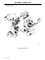
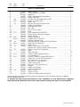
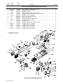
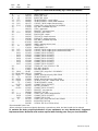
SECTION 6 – PARTS LIST 19. . . . . . . . . . . . . . . . . . . . . . . . . . . . . . . . . . . . . . . . . . . . . . . . . . . . . . . . . . . . . .
WARRANTY
OM-184 227D


OM-184 227 Page 1
SECTION 1 – SAFETY PRECAUTIONS – READ BEFORE
USING
1-1. Symbol Usage
safety_ihom 5/98
Means Warning! Watch Out! There are possible hazards
with this procedure! The possible hazards are shown in
the adjoining symbols.
Y Marks a special safety message.
. Means “Note”; not safety related.
This group of symbols means Warning! Watch Out! possible
ELECTRIC SHOCK, MOVING PARTS, and HOT PARTS hazards.
Consult symbols and related instructions below for necessary actions
to avoid the hazards.
1-2. Induction Heating Hazards
Y The symbols shown below are used throughout this manual to
call attention to and identify possible hazards. When you see
the symbol, watch out, and follow the related instructions to
avoid the hazard. The safety information given below is only
a summary of the more complete safety information found in
the Safety Standards listed in Section 1-4. Read and follow all
Safety Standards.
Y Only qualified persons should install, operate, maintain, and
repair this unit.
Y During operation, keep everybody, especially children, away.
ELECTRIC SHOCK can kill.
Touching live electrical parts can cause fatal shocks
or severe burns. The power circuit and output bus
bars or connections are electrically live whenever
the output is on. The input power circuit and machine
internal circuits are also live when power is on. Incorrectly installed or
improperly grounded equipment is a hazard.
D Do not touch live electrical parts.
D Enclose any connecting bus bars and coolant fittings to prevent
unintentional contact.
D Wear dry, hole-free insulating gloves and body protection.
D Insulate yourself from work and ground using dry insulating mats or
covers big enough to prevent any physical contact with the work or
ground.
D Disconnect input power before installing or servicing this equip-
ment. Lockout/tagout input power according to OSHA 29 CFR
1910.147 (see Safety Standards).
D Use only nonconductive coolant hoses with a minimum length of 18
inches (457 mm) to provide isolation.
D Properly install and ground this equipment according to its Owner’s
Manual and national, state, and local codes.
D Always verify the supply ground – check and be sure that input pow-
er cord ground wire is properly connected to ground terminal in
disconnect box or that cord plug is connected to a properly
grounded receptacle outlet.
D When making input connections, attach proper grounding
conductor first – double-check connections.
D Frequently inspect input power cord for damage or bare wiring – re-
place cord immediately if damaged – bare wiring can kill.
D Turn off all equipment when not in use.
D Do not use worn, damaged, undersized, or poorly spliced cables.
D Do not drape cables over your body.
D Do not touch power circuit if you are in contact with the work,
ground, or another power circuit from a different machine.
D Use only well-maintained equipment. Repair or replace damaged
parts at once. Maintain unit according to manual.
D Wear a safety harness if working above floor level.
D Keep all panels and covers securely in place.
SIGNIFICANT DC VOLTAGE exists after removal of
input power on inverters.
D Turn Off inverter, disconnect input power, and discharge input
capacitors according to instructions in Maintenance Section before
touching any internal parts.
INDUCTION HEATING can cause burns.
D Hot parts and equipment can injure.
D Do not touch or handle induction head/coil
during operation.
D Do not touch hot parts bare-handed.
D Allow cooling period before handling parts or equipment.
D Keep metal jewelry and other metal personal items away from
head/coil during operation.
FIRE OR EXPLOSION hazard.
D Do not overheat parts and adhesive.
D Watch for fire; keep extinguisher nearby.
D Keep flammables away from work area.
D Do not locate unit on, over, or near combustible surfaces.
D Do not install unit near flammables.
D Do not operate unit in explosive atmosphere.
Induction Heating of certain materials, adhesives,
and fluxes can produce fumes and gases. Breathing
these fumes and gases can be hazardous to your
health.
FUMES AND GASES can be hazardous.
D Keep your head out of the fumes. Do not breathe the fumes.
D If inside, ventilate the area and/or use exhaust to remove fumes
and gases.
D If ventilation is poor, use an approved air-supplied respirator.
D Read the Material Safety Data Sheets (MSDSs) and the
manufacturer’s instruction for adhesives, fluxes, metals,
consumables, coatings, cleaners, and degreasers.
D Work in a confined space only if it is well ventilated, or while wearing
an air-supplied respirator. Always have a trained watchperson
nearby. Fumes and gases from heating can displace air and lower
the oxygen level causing injury or death. Be sure the breathing air is
safe.
D Do not heat in locations near degreasing, cleaning, or spraying op-
erations. The heat can react with vapors to form highly toxic and
irritating gases.
D Do not overheat coated metals, such as galvanized, lead, or
cadmium plated steel, unless the coating is removed from the
heated area, the area is well ventilated, and if necessary, while
wearing an air-supplied respirator. The coatings and any metals
containing these elements can give off toxic fumes if overheated.
See coating MSDS for temperature information.

OM-184 227 Page 2
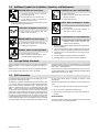
1-3. Additional Symbols for Installation, Operation, and Maintenance
FALLING UNIT can cause injury.
D Use handle and have person of adequate
physical strength lift unit.
D Move unit with hand cart or similar device.
D For units without a handle, use equipment of
adequate capacity to lift unit.
D When using lift forks to move unit, be sure forks are long enough
to extend beyond opposite side of unit.
FLYING METAL OR ADHESIVE can injure eyes.
D Wear approved safety glasses with side
shields or wear face shield.
MOVING PARTS can cause injury.
D Keep away from moving parts such as fans.
D Keep all doors, panels, covers, and guards
closed and securely in place.
MAGNETIC FIELDS can affect pacemakers.
D Pacemaker wearers keep away.
D Wearers should consult their doctor before
going near induction heating operations.
OVERUSE can cause OVERHEATING
D Allow cooling period.
D Reduce output or reduce duty cycle before
starting to heat again.
D Follow rated duty cycle.
STATIC (ESD) can damage PC boards.
D Put on grounded wrist strap BEFORE handling
boards or parts.
D Use proper static-proof bags and boxes to
store, move, or ship PC boards.
H.F. RADIATION can cause interference.
D High-frequency (H.F.) can interfere with radio
navigation, safety services, computers, and
communications equipment.
D Have only qualified person familiar with electronic equipment per-
form this installation.
D The user is responsible for having a qualified electrician promptly
correct any interference problem resulting from the installation.
D If notified by the FCC about interference, stop using the equip-
ment at once.
D Have the installation regularly checked and maintained.
D Keep high-frequency source doors and panels tightly shut.
1-4. Principal Safety Standards
Safety and Health Standards, OSHA 29 CFR 1910, from Superinten-
dent of Documents, U.S. Government Printing Office, Washington, D.C.
20402.
National Electrical Code, NFPA Standard 70, from National Fire Protec-
tion Association, Batterymarch Park, Quincy, MA 02269.
Canadian Electrical Code Part 1, CSA Standard C22.1, from Canadian
Standards Association, Standards Sales, 178 Rexdale Boulevard,Rex-
dale, Ontario, Canada M9W 1R3.
Safe Practices For Occupation And Educational Eye And Face Protec-
tion, ANSI Standard Z87.1, from American National Standards Institute,
1430 Broadway, New York, NY 10018.
1-5. EMF Information
Considerations About Induction Heating And The Effects Of Low Fre-
quency Electric And Magnetic Fields
The following is a quotation from the General Conclusions Section of the
U.S. Congress, Office of Technology Assessment, Biological Effects of
Power Frequency Electric & Magnetic Fields – Background Paper,
OTA-BP-E-53 (Washington, DC: U.S. Government Printing Office, May
1989): “. . . there is now a very large volume of scientific findings based
on experiments at the cellular level and from studies with animals and
people which clearly establish that low frequency magnetic fields can
interact with, and produce changes in, biological systems. While most of
this work is of very high quality, the results are complex. Current scientif-
ic understanding does not yet allow us to interpret the evidence in a
single coherent framework. Even more frustrating, it does not yet allow
us to draw definite conclusions about questions of possible risk or to of-
fer clear science-based advice on strategies to minimize or avoid
potential risks.”
To reduce magnetic fields in the workplace, use the following proce-
dures:
1. Arrange output cable to one side and away from the operator.
2. Do not coil or drape output cable around the body.
3. Keep power source and cable as far away from the operator as
practical.
About Pacemakers:
The above procedures are also recommended for pacemaker wearers.
Consult your doctor for complete information.

OM-184 227 Page 3
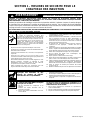
SECTION 1 – MESURES DE SECURITE POUR LE
CHAUFFAGE PAR INDUCTION
safetyihom_fre 5/98
PRENDRE LES MESURES NECESSAIRES POUR EVITER LES RISQUES DE BLESSURES GRAVES, VOIRE
MORTELLES. TENIR LES ENFANTS A DISTANCE. LES PORTEURS D’UN STIMULATEUR CARDIAQUE DOIVENT
PREALABLEMENT CONSULTER LEUR MEDECIN.
Pendant les opérations de chauffage, comme dans la plupart des activités, l’opérateur s’expose à certains dangers.
Le chauffage n’est pas dangereux à condition de prendre certaines mesures. Les consignes de sécurité indiquées
ci-après ne sont qu’un résumé des informations plus détaillées se trouvant dans les normes de sécurité énumérées
à la page suivante. Lire et respecter toutes les normes de sécurité.
LES OPERATIONS D’INSTALLATION, DE FONCTIONNEMENT, DE MAINTENANCE ET DE REPARATION NE DOIVENT
ETRE CONFIEES QU’A DU PERSONNEL QUALIFIE.
LE CHAUFFAGE PAR INDUCTION peut être dangereux.
AVERTISSEMENT
Danger de mort PAR ELECTROCUTION.
Le contact de composants électriques peut
provoquer des accidents mortels ou des brûlures
graves. Le circuit de puissance et les connexions de
sortie sont sous tension lorsqu’on active la sortie. Le
circuit d’alimentation et les circuits internes de la
machine sont également sous tension lorsque
l’alimentation est sur marche. Des équipements
installés ou reliés à la borne de terre de manière
incorrecte sont dangereux.
1. Ne pas toucher des composants électriques sous tension.
2. Envelopper les connexions et raccords de refroidissement pour
éviter tout contact accidentel.
3. Porter des gants d’isolation secs, sans trous, et une protection
corporelle.
4. Isolez-vous de la pièce et du sol avec des tapis ou des
couvertures d’isolation suffisamment grands pour prévenir tout
contact physique avec la pièce ou la terre.
5. Déconnecter l’alimentation avant d’installer l’appareil ou d’en
effectuer l’entretien. Verrouiller ou étiqueter la sortie
d’alimentation selon la norme OSHA 29 CFR 1910.147
(se reporter aux Principales normes de sécurité).
6. Utiliser seulement des tuyaux non conducteurs avec une
longueur minimale de 460 mm pour assurer l’isolement.
7. Installer et mettre cet équipement correctement à la terre
conformément au manuel utilisateur et aux codes nationaux,
gouvernementaux et locaux.
8. Vérifier souvent la terre de l’alimentation – contrôler et s’assurer
que le conducteur de terre du câble d’alimentation est
correctement relié à la borne de terre dans le boîtier de
déconnexion ou que le connecteur est branché à une sortie de
boîtier correctement mise à la terre.
9. En réalisant des connexions d’entrée brancher d’abord le
conducteur de terre approprié – contrôler deux fois les
connexions.
10. Vérifier souvent le bon état du câble d’alimentation ou l’isolation
des fils – remplacer le câble immédiatement s’il est endommagé –
des fils dénudés peuvent provoquer des accidents mortels.
11. Arrêter tous les équipements lorsqu’ils ne sont pas utilisés.
12. Ne pas utiliser des câbles usés, endommagés, sous
dimensionnés ou mal épissés.
13. Ne pas porter les câbles autour de votre corps.
14. Ne pas toucher le circuit électrique si vous êtes en contact avec la
pièce, la terre ou le circuit électrique d’une autre machine.
15. Utiliser seulement des équipements bien entretenus. Réparer ou
remplacer immédiatement des composants endommagés.
Effectuer des travaux d’entretien sur l’appareil selon le manuel.
16. Porter un harnais de sécurité pour effectuer des travaux
au-dessus du sol.
17. Maintenir solidement en place tous les panneaux et couvercles.
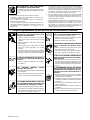
LE CHAUFFAGE PAR INDUCTION peut
provoquer des blessures ou des
brûlures au contact de PIECES
CHAUDES OU DE L’EQUIPEMENT.
1. Ne pas toucher ou manipuler la tête/l’enroulement à induction
pendant le fonctionnement.
2. Tenir les bijoux et autres objets personnels en métal éloignés de
la tête/de l’enroulement pendant le fonctionnement.
3. Laisser refroidir les composants ou équipements avant de les
manipuler.
LE CHAUFFAGE PAR INDUCTION peut
provoquer un incendie.
1. Ne pas surchauffer les composants ni les
adhésifs.
2. Attention aux risques d’incendie: tenir un
extincteur à proximité.
3. Stocker des produits inflammables hors de la
zone de travail.
La mise en place de l’appareil sur, au-dessus ou à
proximité de surfaces inflammables peut être source
d’INCENDIES OU d’EXPLOSION.
1. Ne pas placer l’appareil sur, au-dessus ou à proximité de
surfaces infllammables.
2. Ne pas installer l’appareil à proximité de produits inflammables
3. Ne pas faire fonctionner l’appareil en atmosphère explosive.

OM-184 227 Page 4
DES FUMEES ET DES GAZ peuvent
être dangereux pour votre santé.
Le chauffage à induction génère des fumées et des
gaz. Leur inhalation peut être dangereuse pour votre
santé.
1. Eloigner la tête des fumées. Ne pas respirer les fumées.
2. A l’interieur, ventiler la zone et/ou utiliser un extracteur pour
l’évacuation des fumées et des gaz.
3. Si la ventilation est insuffisante, utiliser un respirateur à
alimentation d’air homologué.
4. Lire les spécifications de sécurité des matériaux (MSDSs) et les
instructions du fabricant concernant les adhésifs, les métaux, les
consommables, les revêtements, les nettoyants et les
dégraisseurs.
5. Travailler dans un espace fermé seulement s’il est bien ventilé ou
en portant un respirateur. Demander toujours à un surveillant
dûment formé de se tenir à proximité. Des fumées et des gaz
provenant du chauffage peuvent déplacer l’air, abaisser le niveau
d’oxygène, et provoquer des lésions ou des accidents mortels.
S’assurer que l’air ambiant ne présente aucun danger.
6. Ne pas chauffer dans des endroits se trouvant à proximité
d’opérations de dégraissage, de nettoyage ou de pulvérisation. La
chaleur peut réagir en présence de vapeurs et former des gaz
hautement toxiques et irritants.
7. Ne pas chauffer des métaux munis d’un revêtement tels que l’acier
galvanisé, plaqué au plomb ou au cadmium, à moins que le
revêtement ne soit enlevé de la zone chauffée, que la zone soit
bien ventilée et, si nécessaire, en portant un respirateur. Les
revêtements et tous les métaux contenant ces éléments peuvent
dégager des fumées toxiques s’ils sont chauffés.
1-1. Dangers supplémentaires de mise en route, de fonctionnement et d’entretien
LA CHUTE DE MATERIEL peut provoquer
des blessures personnelles graves et en-
dommager les équipements.
1. Utiliser la poignée et demander à une personne
ayant la force physique nécessaire pour soulever
l’appareil.
2. Déplacer l’appareil à l’aide d’un charriot ou d’un
engin similaire.
3. Pour les appareils sans poignée utiliser un équipe-
ment d’une capacité appropriée pour soulever
l’appareil.
4. En utilisant des fourches de levage pour déplacer
l’unité, s’assurer que les fourches sont suffisamment
longues pour dépasser du côté opposé de l’appareil.
LA PROJECTION DE PIECES DE METAL ou
DE COLLE peut provoquer des blessures
aux yeux.
1. Porter des lunettes de protection avec des protec-
tions latérales.
DES ORGANES MOBILES peuvent
provoquer des blessures.
1. S’abstenir de toucher des organes mobiles tels que
des ventilateurs.
2. Maintenir fermés et fixement en place les portes, pan-
neaux, recouvrements et dispositifs de protection.
DES CHAMPS MAGNETIQUES CREES PAR
DES COURANTS ELEVES peuvent affecter le
fonctionnement du stimulateur cardiaque.
1. Porteurs de stimulateur cardiaque, restez à distance.
2. Les porteurs d’un stimulateur cardiaque doivent d’a-
bord consulter leur médecin avant de s’approcher
des opérations de chauffage à induction.
UNE UTILISATION INTENSIVE peut provo-
quer un SURCHAUFFEMENT DU MATERIEL.
1. Prévoir une période de refroidissement
2. Réduire le courant de sortie ou le facteur de marche
avant de recommencer le chauffage.
3. Respecter le facteur de marche nominal.
L’ELECTRICITE STATIQUE peut endomma-
ger les composants des tableaux électri-
ques.
1. Etablir la connexion avec la barrette de terre avant
de manipuler des cartes ou des pièces.
2. Utiliser des pochettes et des boîtes antistatiques
pour stocker, déplacer ou expédier des cartes PC.
Il subsiste DU COURANT CONTINU IMPOR-
TANT après la mise hors tension de l’alimen-
tation électrique.
1. Avant de toucher des organes internes, arrêter la
source électrique, débrancher l’alimentation, et dé-
charger les condensateurs d’alimentation conformé-
ment aux instructions indiquées dans la partie main-
tenance.
LE RAYONNEMENT HAUTE FREQUENCE
peut provoquer des interférences avec les
équipements de radio-navigation et de com-
munication, les services de sécurité et les or-
dinateurs.
• Demander seulement à des personnes qualifiées
familiarisées avec des équipements électroniques
de faire fonctionner l’installation.
• L’utilisateur est tenu de faire corriger rapidement par
un électricien qualifié les interférences résultant de
l’installation.
• Si le FCC signale des interférences, arrêter immé-
diatement l’appareil.
• Effectuer régulièrement le contrôle et l’entretien de
l’installation.
• Maintenir soigneusement fermés les portes et les
panneaux des sources de haute fréquence.

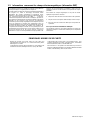
OM-184 227 Page 5
1-2. Informations concernant les champs électro-magnétiques (Information EMF)
Considérations relatives au chauffage à induction et aux effets des
champs électriques et magnétiques basse fréquence.
Le texte suivant est extrait des conclusions générales Département
du Congrès U.S., Office of Technology Assessment, Effets
biologiques des champs magnétiques et électriques basse
fréquence – Background Paper, OTA-BP-E-53 (Washington, DC:
U.S. Government Printing Office, May 1989): “. . . on dispose
maintenant d’importantes découvertes scientifiques reposant sur
des expériences effectuées dans le domaine cellulaire et des études
réalisées sur des animaux et des personnes qui démontrent
clairement que des champs magnétiques basse fréquence peuvent
avoir une interaction et produire des changements dans les
systèmes biologiques. Alors que la plus grande partie de cet ouvrage
est d’une très grande qualité, les résultats sont complexes. La
compréhension scientifique courante ne nous permet pas encore
d’interpréter la preuve fournie dans un seul ouvrage cohérent. Il est
encore plus frustrant de ne pas pouvoir tirer des conclusions
définitives en ce qui concerne les problèmes de risque possible ou de
proposer des recommandations scientifiques claires pour des
stratégies à suivre en vue de minimiser ou de prévenir des risques
potentiels.”
Pour réduire les champs magnétiques sur le poste de travail,
appliquer les procédures suivantes :
4. Disposer le câble de sortie d’un côté à distance de l’opérateur
5. Ne pas enrouler ou draper le câble électrique autour du corps.
6. Placer la source de courant et le câble le plus loin possible de
l’opérateur.
En ce qui concerne les stimulateurs cardiaques
Les procédures ci-dessus concernent également les porteurs de
stimulateur cardiaque. Consulter votre médecin pour un complément
d’information.
PRINCIPALES NORMES DE SÉCURITÉ
Normes de sécurité et de santé, OSHA 29 CFR 1910, from
Superintendent of Documents, U.S. Government Printing Office,
Washington, D.C. 20402.
Code électrique national, NFPA Standard 70, from National Fire
Protection Association, Batterymarch Park, Quincy, MA 02269.
Code électrique du Canada, partie 1, CSA Standard C22.1, from
Canadian Standards Association, Standards Sales, 178 Rexdale
Boulevard,Rexdale, Ontario, Canada M9W 1R3.
Safe Practices For Occupation And Educational Eye And Face
Protection, ANSI Standard Z87.1, from American National Standards
Institute, 1430 Broadway, New York, NY 10018.

OM-184 227 Page 6
SECTION 2 – INSTALLATION
2-1. Specifications
Output
Frequency
Rated Output
Required
Reflective
Amperes Input at
Rated Load Output 50
or 60 Hz, Three-Phase
Overall Dimensions Weight
Frequency
Inductance
460 V KVA KW
10 To 50 kHz
25 kW At
100% Duty
Cycle – Max
750 A (RMS),
700 V (RMS)
2.5 To 50 µh
39
0.29*
30.8 27.19
Length: 31 in
(787 mm)
Width: 16 in
(406 mm)
Height: 27 in
(686 mm)
165 lb
(75 kg)
*While idling
WARNING
HIGH-FREQUENCY RADIATION can interfere with radio navigation, safety services,
computers, and communications equipment.
• Have only qualified person familiar with electronic equipment perform this installation.
• The user is responsible for having a qualified electrician promptly correct any interference problem resulting from the installation.
• If notified by the FCC about interference, stop using the equipment at once.
• Have the installation regularly checked and maintained.
• Keep high-frequency source doors and panels tightly shut.
Ref. ST-801 826-C
Tools Needed:
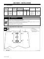
2-2. Connecting Head/Coil to Power Source
1 Rear Panel
2 Connecting Block
. Do Not Exceed 58 in lb
(6.6 N
.
m) of torque when
making connections.
7/16 in
2
1

OM-184 227 Page 7
sb7.1* 3/93 - Ref. S-0004-A / Ref. S-0750 / Ref. ST-801 826-C
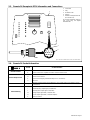
2-3. Remote 14 Receptacle RC14 Information and Connections
1 Front Panel
2 Plug
3 Threaded Collar
4 Keyway
5 Remote 14 Receptacle RC14
(See Section 2-4)
To connect to receptacle, align key-
way, insert plug, and tighten
threaded collar.
2
3
AJ
B
K
I
C
L
NH
D
M
G
E
F
4
5
1
2-4. Remote 14 Socket Information
Socket Socket Information
A
+24 volts dc.
Remote Contactor
B
Contact closure to A completes 24 volts dc contactor control circuit.
C
Command reference; +10 volts dc.
D
Control circuit common.
Remote Output Control
E
Input command signal (potentiometer wiper or 0 to +10 volts dc).
G
Not used.
Power Source Limit F, J
Absence of internal contact closure between F and J signals power source failure to remote
control device.
H
Coil loss compensation value.
H
I
Actual frequency output signal (1 volt/10 kHz).
I
L
Average power output signal (1 volt/5 kW).
Remote Metering
M
Voltage output signal RMS (1 volt/100 volts).
N
Current output signal RMS (1 volt/100 amperes).
K
Chassis common.

OM-184 227 Page 8
Ref. ST-801 825-C
Tools Needed:
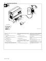
2-5. Connecting Input Power
3/8 in
5/16 in
Have only qualified persons make this
installation.
Remove wrapper.
1 Line Disconnect Device Of Proper
Rating
Obtain and install line disconnect device.
2 Fuse Block Cover
Remove fuse block cover.
3 Input Conductors
4 Grounding Conductor
Select size and length using Section 2-6.
Conductor rating must comply with national,
state, and local electrical codes. Route input
power cord through strain relief on rear panel
to fuse block.
5 Strain Relief Connector
Insert conductors through strain relief.
6 Input Fuse Block
7 Power Source Ground Terminal
Connect grounding conductor to ground
terminal first. Then connect input conductors
to fuse block.
8 Disconnect Device Ground Terminal
Install and connect grounding conductor and
input conductors in conduit or equivalent to
deenergized line disconnect device.
Connect grounding conductor first, then line
input conductors.
Be sure grounding conductor goes to an earth
ground.
Reinstall fuse block cover.
Tighten strain relief, and reinstall wrapper.
9 Overcurrent Protection
Select type and size using Section 2-6. Install
into deenergized line disconnect device
(fused disconnect switch shown).
9
8
1
3
4
5
2
6
7

OM-184 227 Page 9
2-6. Electrical Service Guide
Input Voltage 460
Input Amperes At Rated Output 39
Max Recommended Standard Fuse Or Circuit Breaker Rating In Amperes 60
Min Input Conductor Size In AWG/Kcmil 8
Max Recommended Input Conductor Length In Feet (Meters) 248 (76)
Min Grounding Conductor Size In AWG/Kcmil 10
Reference: 1993 National Electrical Code (NEC). S-0092J
SECTION 3 – OPERATION
Ref. ST-801 826-C
3-1. Controls
1 Power Adjust Control
Use control to select power
between the minimum and
maximum output of the power
source. The numbers around the
control are in kilowatts (kW).
2 Remote Power Control Switch
Use switch to select way of
controlling unit output.
For front panel control, place switch
in Panel position.
For remote control, place switch in
Remote 14 position. Connect
controller or pendant control to
Remote 14 receptacle (see Section
2-3).
3 Power Switch With Indicator
Light
Use switch to turn unit, fan motor,
and indicator light On and Off.
Unit is ready to heat 10 seconds
after Power switch is placed in On
position.
4 Ground Fault Test Switch
Use switch to test ground fault cir-
cuitry.
1
2
3
4

OM-184 227 Page 10
SECTION 4 – MAINTENANCE & TROUBLESHOOTING
4-1. Routine Maintenance
Y Disconnect power
before maintaining.
. Maintain more often
during severe conditions.
3 Months
Clean and tighten
output connections.
Repair or replace
cracked cables
and cords.
6 Months
Replace damaged or
unreadable labels.
Blow out or vacuum
inside.
4-2. Overheating
Thermostats TP1, TP2, and TP3 protect the unit from damage due to overheating. If one or more of the heat sinks get
too hot, TP1, TP2, and/or TP3 opens and output stops. The fan keeps running to cool the heat sink(s). Wait several
minutes before trying to heat.
4-3. Automatic Shutdown Protection
This unit automatically shuts down upon sensing certain fault conditions, such as an out-of-range frequency condition,
short circuit load condition, or an open circuit (no load) condition. The unit also has automatic voltage limiting and
power ratio limiting, which limits the output power based on improper load impedance.
Ref. ST-801 826-C
Tools Needed:
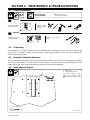
4-4. Safety Interlock Switch
1 Rear Panel
2 Safety Interlock Switch
The safety interlock switch
prevents the contactor from
energizing with the wrapper off the
unit.
3/8 in
2
1

OM-184 227 Page 11
Ref. ST-801 826-A
Tools Needed:
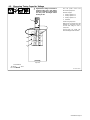
4-5. Measuring Tuning Capacitor Voltage
Y Significant AC voltage can remain on
capacitors after unit is Off. Always
check ALL capacitors as shown to be
sure they have discharged before
working on unit.
3/8 in
Turn Off power source and
disconnect input power.
Remove wrapper.
1 Tuning Capacitor C1
2 Tuning Capacitor C2
3 Tuning Capacitor C3
4 Voltmeter
Check tuning capacitors.
Measure the ac voltage across the
terminals on capacitors every 30
seconds until voltage is near 0
(zero) volts.
Proceed with job inside unit.
Reinstall wrapper when finished.
4
Top View
1
2
3

OM-184 227 Page 12
Ref. ST-801 826-C / Ref. 801 828-C
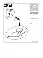
4-6. Ground Fault Protection
Ground fault protection circuitry
automatically shuts down the power
source output if a potentially
hazardous condition exists at the
heating device connected to the
power source (e.g. insulation has
broken down on a heating blanket
causing the conductor to come into
contact with the workpiece or a
heating coil touches the workpiece
causing a short in the output circuit).
The supplied ground lead must be
connected between the workpiece
and power source to provide
proper ground fault protection
from a short in the output circuit.
1 Power Source
2 Receptacle
3 Plug
To connect plug, align key with key-
way, insert end into receptacle, and
rotate plug until tight.
4 Handle
5 Magnet
6 Workpiece
Use handle to place magnet on the
workpiece.
1
2
3
4
5
6

OM-184 227 Page 13
Ref. ST-801 826-A
Tools Needed:
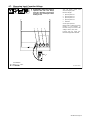
4-7. Measuring Input Capacitor Voltage
3/8 in
Y Significant DC voltage can remain on
capacitors after unit is Off. Always
check ALL capacitors as shown to be
sure they have discharged before
working on unit.
Turn Off power source and
disconnect input power.
Remove wrapper.
1 Input Capacitor C2
2 Input Capacitor C1
3 Input Capacitor C4
4 Input Capacitor C3
5 Voltmeter
Check input capacitors.
Measure the dc voltage across the
positive (+) and negative (–)
terminals every 30 seconds until
voltage is near 0 (zero) volts.
Proceed with job inside unit.
Reinstall wrapper when finished.
12 34
5

OM-184 227 Page 14
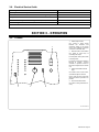
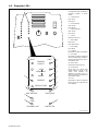
4-8. Diagnostic LED’s
Ref. ST-801 826-B
1 Diagnostic LED’s
Use diagnostic LED’s to determine
operating condition of power
source.
2 Current Source
Limit: 110 A
Fault: 115 A
3 Over Frequency
Limit: 50 kHz
Fault: 55 kHz
4 Under Frequency
Limit: 10 kHz
Fault: 5 kHz
5 Current
Reactive Limit: 700 A
6 Tank Voltage
Limit: 670 V
Fault: 1100 V Peak
7 Line Voltage
Fault: ±20 %
8 Contactor
Lights when contactor is energized.
9 Over Temp
Lights when contactor is energized
and over temperature condition is
present. Also indicates top cover is
removed from unit.
10 Tank Current
Fault Value Preset At Factory
11 Ground Fault
Lights when the ground fault
circuitry detects a short in the
output circuit between the
workpiece and power source, or
when test switch is pressed to test
ground fault circuitry.
12 Load
Lights when no load or insufficient
load is present to couple with the
coil or blanket.
1
LIMITFAULT
CURRENT
SOURCE
OVER
FREQUENCY
UNDER
CURRENT
TANK VOLTAGE
LINE VOLTAGE
CONTACTOR
OVERTEMP
2
3
4
5
6
8
7
12
10
11
GROUND FAULT
LOAD
9

OM-184 227 Page 15
4-9. Troubleshooting
Trouble Remedy
No heat output. Replace building line fuse or reset circuit breaker.
Secure head/coil connecting plate to power source connecting block (see Section 2-2).
Check and replace Power switch if necessary.
Connect power source to proper input voltage or check for low line voltage.
No heat output; fan motor continues to run. Safety interlock switch open. Reinstall wrapper (see Section 4-4).
Thermostat(s) TP1, TP2, and/or TP3 open (overheating). Allow fan to run; the thermostat(s) will close
when the unit has cooled (see Section 4-2).
Low heat output. Check tuning of induction heating output system.
Current Source Fault LED (red) on. Turn power off and back on again to power source one time. If fault does not clear, contact authorized
Factory Service Agent.
Over Frequency Fault LED (red) on. Check for shorted coil or blanket.
Under Frequency Fault LED (red) on. Check for open circuit coil or blanket.
Current Fault LED (red) on. Check for shorted turn(s) in coil or blanket.
Tank Voltage Fault LED (red) on. Check for unloaded (empty) coil.
Check for arcing between turns.
Line Voltage Fault LED (red) on. Check input line voltage.
Ground Fault LED (red) on. Check for output path to ground.
Check for human path to ground.
Load Fault LED (red) on. Check for loose coupling between coil or blanket and workpiece or pipe.
Over Temperature Fault LED (yellow) on. Check door switch.
Check for fan operation.
Clean unit.
Current Source Limit LED (yellow) on. Check coupling between coil and load.
Over Frequency Limit LED (yellow) on. Check for correct tank capacitance.
Check for shorted turns.
Under Frequency Limit LED (yellow) on. Check for correct tank capacitance.
Current Limit LED (yellow) on. Check tank capacitance.
Tank Voltage LED (yellow) on. Check tuning of system (see Section 4-10).
4-10. Tuning Chart
Y Energizing contactor without at least 1 tuning capacitor in output circuit will damage power
source.
DO NOT operate power source without at least 1 tuning capacitor in output circuit.
Voltage* Current (Amperage)* Frequency (KHz) Corrective Action
High Low Low Lower inductance or decrease matching transformer turns ratio
High Low High Add capacitance
High Low Mid-Range Decrease matching transformer turns ratio and add capacitance
Low High Low Lower capacitance
Low High High Increase matching transformer turns ratio, or lower capacitance and
increase inductance
Low High Mid-Range Increase matching transformer turns ratio and lower capacitance
*High voltage > 650 V rms; Low voltage < 400 V rms; Operating current range: 0 to 750 A rms
The power source is factory set for 4.5 mfd, but is capable of being set for 6 mfd. If a certain application requires the higher capacitance setting, remove
insulator from front capacitor and connect with supplied hardware.

OM-184 227 Page 16
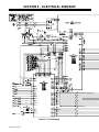
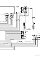
SECTION 5 – ELECTRICAL DIAGRAM
Figure 5-1. Circuit Diagram
La page est en cours de chargement...
La page est en cours de chargement...
La page est en cours de chargement...
La page est en cours de chargement...
La page est en cours de chargement...
La page est en cours de chargement...
La page est en cours de chargement...
La page est en cours de chargement...
-
 1
1
-
 2
2
-
 3
3
-
 4
4
-
 5
5
-
 6
6
-
 7
7
-
 8
8
-
 9
9
-
 10
10
-
 11
11
-
 12
12
-
 13
13
-
 14
14
-
 15
15
-
 16
16
-
 17
17
-
 18
18
-
 19
19
-
 20
20
-
 21
21
-
 22
22
-
 23
23
-
 24
24
-
 25
25
-
 26
26
-
 27
27
-
 28
28


Miller Intellifire 250 Le manuel du propriétaire
- Catégorie
- Système de soudage
- Taper
- Le manuel du propriétaire
- Ce manuel convient également à
dans d''autres langues
Documents connexes
-
Miller LA193767 Le manuel du propriétaire
-
-
-
-
-
-
-
-
-