GE Monogram ZIF360NHRH Guide d'installation
- Catégorie
- Frigos
- Taper
- Guide d'installation
Ce manuel convient également à

Installation
Instructions
31-49078-1
224D2601P003
04-15 GE
36” Built-In All-Refrigerators
and All-Freezers
monogram.com

2
Safety Information
BEFORE YOU BEGIN
Read these instructions completely and carefully.
•
IMPORTANT – Save these instructions for local
inspector’s use. Observe all governing codes and ordi-
nances.
• Note to Installer – Be sure to leave these instructions
with the Consumer.
• Note to Consumer – Keep these instructions with
your Owner’s Manual for future reference.
If you received a damaged unit, you should immediately
contact your dealer or builder.
Skill Level – Installation of this unit requires basic
mechanical, carpentry and plumbing skills. Proper
installation is the responsibility of the installer. Product
failure due to improper installation is not covered under the
GE Appliance Warranty.
See the Owner’s Manual for warranty information.
This is the safety alert symbol. This symbol alerts you to potential hazards that can kill or hurt you and others. All safety
messages will follow the safety alert symbol and the word “DANGER”, “WARNING”, or “CAUTION”. These words are defined as:
Indicates a hazardous situation which, if not avoided, will result in death or serious injury.
Indicates a hazardous situation which, if not avoided, could result in death or serious injury.
Indicates a hazardous situation which, if not avoided, could result in minor or moderate injury.
WARNING
DANGER
CAUTION
For Monogram local service in your area, call 1.800.444.1845.
For Monogram service in Canada, call 1.800.561.3344
For Monogram Parts and Accessories, call 1.800.626.2002.
www.monogram.com
WARNING
Electrical Shock Hazard.
Plug into a grounded 3-prong outlet.
Do not remove the ground prong.
Do not use an adapter.
Immediately replace electric cords that become frayed
or damaged.
Do not use an extension cord with this appliance.
Failure to follow these instructions can result in death,
fire, or electrical shock.
Follow the instructions in the section Grounding the
Unit.
WARNING
Tip Over Hazard.
These appliances are top heavy, especially with any doors open, and must be secured to prevent tipping forward
which could result in death or serious injury. Read and follow the entire installation instructions for securing the
appliance with the anti-tip system.
WARNING
Explosion Hazard.
Keep flammable materials and vapors, such as gasoline, away from appliance. Failure to do so can result in fire,
explosion, or death.
WARNING
To reduce the risk associated with choking, do not allow children under 3 years of age to have
access to small parts during the installation of this product.
CAUTION
Lifting Hazard
This unit is very heavy. To reduce the risk of person injury during maneuvering and installing this appliance, 3
people are required for proper installation.

CONSIGNES DE SÉCURITÉ
Ce symbole représente une alerte de sécurité. Ce symbole vous avise de dangers possibles pouvant causer la mort, des
blessures ou autres. Tous les messages de sécurité seront précédés du symbole d’alerte de sécurité ainsi que des mots «
DANGER », « AVERTISSEMENT » ou « MISE EN GARDE ». Ces messages sont les suivants :
Signale une situation qui présente un danger imminent et qui, si elle n’est pas évitée, entraînera des bles
sures graves, voire la mort.
Signale une situation qui présente un danger imminent et qui, si elle n’est pas évitée, peut entraîner des
blessures graves, voire la mort. .
Signale une situation qui présente un danger imminent et qui, si elle n’est pas évitée, peut entraîner des
blessures mineures ou graves.
AVERTISSEMENT
DANGER
ATTENTION
3
AVERTISSEMENT
Risque de basculement
Ces réfrigérateurs présentent une partie supérieure lourde, en particulier avec une porte ouverte; ils doivent donc
être fixés pour prévenir le basculement vers l’avant et le risque concomitant de blessure grave ou fatale. Lisez et
suivez les instructions d’installation complètes pour l’installation du système anti-basculement.
AVERTISSEMENT
Risque d’explosion.
Conservez les matériaux et vapeurs inflammables tels que l’essence à l’écart de votre réfrigérateur. Le non-re-
spect de cette instruction peut entraîner un risque d’incendie, d’explosion ou de décès.
AVERTISSEMENT
Pour réduire le risque d’étouffement pendant l’installation de ce produit, ne pas laisser les
petites pièces à la portée des enfants âgés de moins de 3 ans.
ATTENTION
Risque associé à la manutention d’une charge lourde
Ce réfrigérateur est très lourd. Pour réduire le risque de blessure lors de la manutention de ce réfrigérateur, trois
(3) personnes sont nécessaires pour procéder à l’installation appropriée du modèle 36 pouces, quatre (4) pour
l’installation des modèles 42 ou 48 pouces.
AVERTISSEMENT
Risque de choc électrique.
Branchez l’appareil dans une prise triple avec terre.
Ne retirez pas la broche de terre.
N’utilisez pas d’adaptateur.
Le non-respect de ces instructions peut entraîner des ris-
ques d’incendies, des chocs électriques ou la mort.
Remplacer immédiatement tout cordon électrique
effiloché ou endommagé.
N’utilisez pas de rallonge avec cet appareil.
Le non-respect de ces instructions peut entraîner des ris-
ques d’incendies, des chocs électriques ou la mort.
Suivez les instructions de la section Mise à la terre du
réfrigérateur.

Contents
4
Safety 2, 3
Instructions for Standard Installation 5-21
Planning Guide
The Installation Space 6
Dimensions and Clearances 6-7
Customization Basics 8
Refrigerator Location 8
1/4” Framed Panel Dimensions 9
3/4” Overlay Panel Dimensions 9
Side Panels 10
ZUG2 Grille Panel Dimensions 10
130° Door Swing 11
Installation Instructions
Tools, Hardware, Materials 12
Grounding the Unit 12
Step 1. Remove Packaging 13
Step 2. Install Water Line 13
Step 3. Install Side Panels 13
Step 4. Anti-Tip Procedures 14-16
Step 5. Level Unit 17
Step 6, Secure Unit to Wall 17
Step 7. Adjust Door Swing 18
Step 8. Install Grille Panel 18
Step 9. Install Framed Panels 19
Step 9A. Install Overlay Panels 20
Step 10. Connect Water Supply 21
Step 11. Start Icemaker 21
Step 12. Install Toekick 21
Instructions for Flush Installation 22-38
Planning Guide
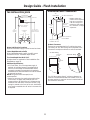
The Installation Space 23
Dimensions and Clearances 23-24
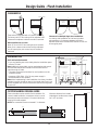
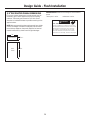
Custom Handle Design Guide 24
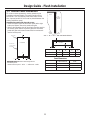
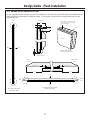
1/2” Overlay Panel Dimensions 25
3/4” Decorative Panel Dimensions 26
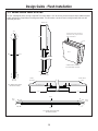
3/4” Raised Door Panel Routing 27
3/4” Raised Grille Panel Routing 28
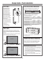
Side Panels 29
Side Cleats 29
ZUG2 Grille Panel Dimensions 29
Unified Door Panel Dimensions 29
Refrigerator Location 29
Installation Instructions
Tools, Hardware, Materials 30
Grounding the Unit 30
Step 1. Remove Packaging 31
Step 2. Install Water Line 31
Step 3. Install Side Panels 31
Step 4. Install Case Trim 32
Step 5. Anti-Tip Bracket 32-34
Step 6. Level Unit 34
Step 7. Adjust Door Swing 35
Step 8. Install Grille Panel 35
Step 9. Install overlay Panels 36
Step 10. Connect Water Supply 37
Step 11. Start Icemaker 37
Step 12. Install Toekick 37
Instructions for Stainless Steel Installation 38-49
Planning Guide
The Installation Space 39
Dimensions and Clearances 39-40
Customization Basics 41
Refrigerator Location 41
130° Door Swing 42
Installation Instructions
Tools, Hardware, Materials 43
Grounding the Unit 43
Step 1. Remove Packaging 44
Step 2. Install Water Line 44
Step 3. Install Side Panels 44
Step 4. Anti-Tip Bracket 45-47
Step 5. Level Unit 47
Step 6, Secure Unit to Wall 48
Step 7. Adjust Door Swing 48
Step 8. Connect Water Supply 49
Step 9. Start Icemaker 49
Step 10. Install Toekick 49

Instructions for Standard Installation
5

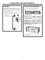
Design Guide - Standard Installation
36" Frame to
Frame Width
*84" From
Floor to
Top Frame
35"
Case Width
*83-1/2"
at
Rear
25-3/8" Case Depth
Depth Including
Handles 26-7/8"
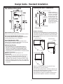
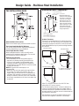
THE INSTALLATION SPACE
Water And Electrical Locations
Electrical and water supply must be located as shown.
The Cutout Depth Must Be 24” Minimum
The unit will project forward, slightly beyond adjacent
cabinetry, depending on your installation.
Cutout Depth Beneath a Soffit:
When installed beneathh a soffit, the soffit cannot
exceed the 24” installation depth shown. The top case
trim overlaps the bottom of the soffit.
Additional Specifications
• A 115 volt 60Hz., 15 or 20 amp power supply is
required. An individual properly grounded branch
circuit or circuit breaker is recommended. Install
a properly grounded 3-prong electrical receptacle
recessed into the back wall. Electrical must be located
on rear wall as shown.
NOTE: GFI (ground fault interrupter) is not
recommended.
• Water line can enter the opening through the floor
or back wall. The water line should be 1/4” O.D.
copper tubing or GE QuickConnect
™
kit between the
cold water line and water connection location, long
enough to extend to the front of the unit. Installation
of an easily accessible shut-off valve in the water line
is required.
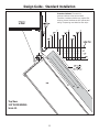
DIMENSIONS AND CLEARANCES
* Shipping height. The
product can be adjusted
to fit into a cutout that
is 84-1/2” max. height.
Note that the top case
trim at the front is 1/2”
higher and will overlap
upper cabinetry or soffit.
Use leveling legs and
wheels for a maximum 1”
height adjustment.
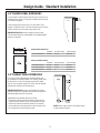
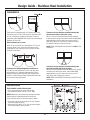
Product Clearances
These units are equipped with a 3-position door stop.
The factory set 115° door swing can be adjusted to 90°
if clearance to adjacent cabinets or walls is restricted.
Order WX14X99 door stop for precise settings between
90° and 130°.
130° Door Swing
90° Door Swing
90° Door Swing
4” Minimum
to a Wall
90°
23-7/8”
Case Behind
Frame
36-3/4”
Allow 25” minimum clearance for a full 130° door
swing. Allow 15” for pan removal.
For a 90° door swing, allow 4” minimum clearance to a
wall. If the 90° doorstop position is used, pan access is
maintained but pan removal is restricted.
See illustration on page 11 to determine door swing
interaction with adjacent cabinets or countertops.
115° Door Swing
6

Design Guide - Standard Installation
7
These units are equipped with a 3-position door stop.
The factory set 115° door swing can be adjusted to 90°
or 130° if clearance to adjacent cabinets or walls is
restricted. Order WX14X99 door stop for precise settings
between 90° and 130°.
When Installed into a corner:
Allow 25” for a full 130° door swing. Allow 15” for pan
removal. Allow 4” min. clearance when door swing
is adjusted to a 90° opening for pan access, but pan
removal is restricted.
25"
Min. to
Wall
130°
130° Door
Swing
CLEARANCES
ZUG2, ZUGSS2 Unified Grille Panel Kit
• If you are installing two units, side by side,
the installation space must be 71-1/2” wide.
NOTE: Additional cutout width may be required when
side panels are used. Add side panel thickness
to the finished cutout to calculate rough-in width.
• The water and electrical locations for each product
must be located as shown.
• A separate 115V, 60Hz., 15 or 20 amp power supply
is recommended for each product.
Clearances for Multiple Single Door Installations
In a side-by-side installation of a left and right door
swing product, a 1” clearance between the units is
required. Order ZUGSS2 Stainless Steel Unified Grille
Panel Kit or ZUG2 Custom Panel Unified Grille Panel Kit
for one continuous grille panel.
Clearances for two products installed side-by-side
with the same (left or right) door swing
Allow 2” minimum clearance between the products
to prevent door swing interference. Order the WX14X99
adjustable door stop to reduce the factory set 115°
door swing. Allow 15” minimum to a wall to achieve
full drawer extension and pan removal.
NOTE: ZUG2 and ZUGSS2 Grille Panel Kit will NOT fit this
installation.
2"
15"
Clearances for two products installed side-by-side
with right and left side hinges together
Allow 5” minimum between the two products to prevent
one door from striking the other. Use the WX14X99
adjustable door stop to reduce the factory set 115°
door swing and to allow pan removal.
NOTE: ZUG2 and ZUGSS2 Grille Panel Kit will NOT fit this
installation.
5"
INSTALLATION

Design Guide - Standard Installation
8
CUSTOMIZATION BASICS:
Framed or Overlay Panels, Custom
Handles and Accessory Kits
Trimmed models are designed to be customized with
decorative panels. Field installed custom door and grille
panels are required.
Optional Accessory Kits
• ZKHSS2: Monogram Tubular Stainless Steel handles
designed to fit 3/4” overlay panels.
• ZKHPSS1: Pro Tubular Stainless Steel handle designed
to fit 3/4” overlay panels.
• ZUG2: For side-by-side installation of two trimmed
models. This kit provides for the installation of a unified
custom grille panel to span the width of two units using
a framed or overlay panel.
REFRIGERATOR LOCATION
• Do not install the refrigerator where the temperature
will go below 55°F (13°C). It will not run often enough
to maintain proper temperatures.
• Do not install the refrigerator where temperatures will
go above 100°F (37°C). It will not perform properly.
• Do not install the refrigerator in a location exposed to
water (rain, etc.) or direct sunlight.
• Install it on a floor strong enough to support it fully
loaded.

Design Guide - Standard Installation
9
If you choose to install framed panels, they must be cut to
the dimensions shown. The panels will slide into the frame
on the door and grille.
If the custom panel is less than 1/4” thick and if it fits
loosely in the door frame, it can be backed up with a piece
of filler material or foam tape to improve the fit.
IMPORTANT NOTE: Maximum weight for door panel
is 67 pounds. Maximum total weight for assembled grille
panel is 11 pounds.
3/4” OVERLAY PANEL DIMENSIONS
For a more custom appearance, overlay panels may
be installed on trimmed models. The overlay panel must
be secured to a 1/4” thick backer panel which slides
into the trim. A spacer panel 0.10” thick must be placed
between the overlay and backer panel.
IMPORTANT NOTE: Maximum total weight for assem-
bled door panel is 67 pounds. Maximum total weight for
assembled grille panel is 11 pounds.
Assemble the panels with glue and screws.
• Center the spacer panel on the backer panel, left to
right and top to bottom. Secure the panels with glue.
• Center the spacer and backer panel on the overlay
panel and secure with glue and screws. Screws must
be countersunk into the backer panel.
Framed Panel Dimensions
A (Width) B (Grille Height) C (Door Height)
1/4” Framed Panel 33-7/8” 8-7/8” 69-5/16”
Overlay Panel Dimensions
A (Width) B (Grille Height) C (Door Height)
1/4” Backer Panel 33-7/8” 8-7/8” 69-5/16”
0.10” Spacer Panel 32-1/2” 7-5/8” 67-15/16”
3/4” Overlay Panel 34-1/8” 9” 69-9/16”
NOTE: Left-to-right offset is not always equal
to top-to-bottom offset.
1/4"
Panel
Door
5/16"
Trim
Reveal
1/4” FRAMED PANEL DIMENSIONS

10
SIDE PANELS
Side panels must be used whenever the sides of the unit
will be exposed. The 1/4” side panels will slip into the
side case trim. Secure the panels to the unit with stick-
on hook and loop fastener strips. Order the side panels
from the cabinet manufacturer.
• Cut a notch in the top front corner as shown to allow
clearance for corner keys in the front side trim.
ZUG2 GRILLE PANEL DIMENSIONS
The ZUG2 unified grille panel kit provides for the
installation of a framed or overlay grille panel.
* Depending on
installation height.
Assemble the overlay panels in the same manner
as the door panel.
Framed Panel Dimensions
A (Width) B (Height)
1/4” Framed Panel 69-7/8” 8-7/8”
Overlay Panel Dimensions
A (Width) B (Height)
1/4” Backer Panel 69-7/8” 8-7/8”
0.10” Spacer Panel 68-1/2” 7-5/8”
3/4” Overlay Panel 70-1/8” 9”
IMPORTANT NOTE: The maximum weight for the
unified grill is 25 pounds.
Design Guide - Standard Installation
*84"
2-9/16"
24"
*3" to 4"
3/16"
1-7/8"

Design Guide - Standard Installation
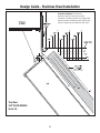
11
Top View
130° DOOR SWING
Scale 1:1
Frameless Cabinets: The case trim
overlaps cabinets at the top and sides.
Therefore, frameless cabinets may require filler
strips to prevent interference with cabinet door
swing. The opening must allow for filler strips.

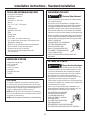
Installation Instructions - Standard Installation
12
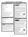
HARDWARE SUPPLIED
• Water filter bypass plug
• Anti-Tip brackets
• 3 lag screws
• 2 Hair Pin Cotters
• 4 washers
• 5 toggles with bolts
• Toekick
TOOLS AND MATERIALS REQUIRED
• Tin snips to cut banding
• #2 Phillips screwdriver
• Stepladder
• Drill and 1/2”, 3/16” bits
• Bucket
• 1/4”, 1/2”, 5/16”, 7/16” socket
• Level
• Safety glasses
• Appliance hand truck
• Pliers
• Tubing cutter
• Stud finder
• 7/16” and 1-1/4” open-end wrench
• 1/4” copper water line tubing or GE SmartConnect
™
Refrigerator Tubing kits
• Water shut-off valve (optional but recommended)
• Custom panels for door and grille panel
• Screws to secure unit to cabinetry
• Stick-on hook and loop fastener strips for
1/4” side panels
FLOORING
For proper installation, this product must be placed
on a level surface of hard material that is at the same
height as the rest of the flooring. This surface should be
strong enough to support a fully loaded refrigerator or
freezer, or approximately 1,200 lbs. per unit.
NOTE: Protect the finish of the flooring. Cut a large sec-
tion of the cardboard carton and place under the prod-
uct where you are working.
NOTE: Not recommended for installation on carpeted flooring.
GROUNDING THE UNIT
WARNING
Electrical Shock Hazard.
Failure to follow these instructions can result in death,
fire, or electrical shock.
The power cord of this appliance is equipped with a
3-prong (grounding) plug which mates with a standard
3-prong (grounding) wall receptacle to minimize the
possibility of electric shock hazard from this appliance.
Have the wall outlet and circuit checked by a qualified
electrician to make sure the outlet is properly grounded.
Where a standard 2-prong wall outlet is encountered, it
is your personal responsibility and obligation to have it
replaced with a properly grounded 3-prong wall outlet.
DO NOT, UNDER ANY
CIRCUMSTANCES, CUT OR REMOVE
THE THIRD (GROUND) PRONG
FROM THE POWER CORD.
DO NOT USE AN ADAPTER PLUG
TO CONNECT THE REFRIGERATOR
TO A 2-PRONG OUTLET.
DO NOT USE AN EXTENSION CORD WITH THIS
APPLIANCE.
LA TERRE DE L’UNITÉ
AVERTISSEMENT
Risque de choc électrique.
Le non-respect de ces instructions peut entraîner des
risques d’incendies, des chocs électriques ou la mort.
Le cordon d’alimentation de cet appareil est équipé
d’une fiche à trois broches (pour une mise à la terre)
qui s’adapte à la prise de courant standard à 3
broches (pour une mise à la terre) pour minimiser les
risques de chocs électriques par cet appareil.
Faites vérifier la prise murale et le circuit électrique par
un électricien qualifié pour s’assurer que le système est
correctement mis à la terre.
Dans le cas d’une prise biphasée, l’installateur a la
responsabilité et l’obligation de la remplacer par une
prise triphasée correctement mise à la terre.
NE COUPEZ PAS OU N’ENLEVEZ
PAS, SOUS AUCUN PRÉTEXTE,
LA TROISIÈME BROCHE DE
MISE À LA TERRE DU CORDON
D’ALIMENTATION.
N’UTILISEZ PAS D’ADAPTATEUR
POUR BRANCHER LE
RÉFRIGÉRATEUR À UNE PRISE BIPHASÉE.
N’UTILISEZ PAS DE RALLONGE AVEC CET APPAREIL.

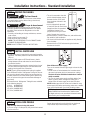
Installation Instructions - Standard Installation
13
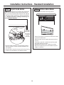
STEP 3 INSTALL SIDE PANELS
Skip this step when not using side panels
If you are using 1/4” side panels, they should be inserted
into the case trim.
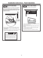
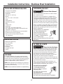
STEP 1 REMOVE PACKAGING
WARNING
Tip Over Hazard.
Product is much heavier at the top than at the bottom
– be careful when moving. When using a hand truck,
handle from side only.
AVERTISSEMENT
Risque de basculement
Le produit est beaucoup plus lourd en haut qu’en bas.
Il faut être prudent lors des déplacements. Si un diable
est utilisé, il faut soulever le réfrigérateur sur le côté
seulement.
• Carefully cut banding at the top and bottom, remove
outer carton.
• Slide out back corner posts (2).
• Slide carton off top of cabinet.
NOTE: IT IS NOT NECESSARY TO LAY CABINET DOWN
IN ORDER TO REMOVE SKID!
NOTE: DO NOT ATTEMPT TO ROLL UNIT OFF SKID.
STEP 2 INSTALL WATER LINE
• A cold water supply is required for automaticicemaker
operation. The water pressure must be between 40 and
120 p.s.i.
• Route 1/4” OD copper or GE SmartConnect
™
plastic
tubing between house cold water line and the water
connection location.
• Tubing should be long enough to extend to the front of
the unit. Allow enough tubing to accommodate bend
leading into the water line connection.
NOTE: The only GE approved plastic tubing is supplied
in the GE SmartConnect
™
Refrigerator Tubing kits. Do not
use any other plastic water supply line because the line
is under pressure at all times. Other types of plastic may
crack or rupture with age and cause water damage to
your home.
GE SmartConnect
™
Refrigerator Tubing Kits are available
in the following lengths:
2’ (.6 m) WX08X10002
8’ (2.4 m) WX08X10006
15’ (4.6 m) WX08X10015
25’ (7.6 m) WX08X10025
• The unit is secured to the skid
with 4 slotted tie-down straps.
Remove the four 5/16” bolts
from the base channels in the
tie-downs.
• Unit is shipped with two sets
of toe kicks. One for Flush Inset
(longer) and One for standard
installation (shorter). Pick
proper toe kick for your instal-
lation. Discard other toe kick.
• Remove toekick, custom handle trim, and wall bracket.
Set aside for final installation.
• Lift the unit off the skid with an appliance dolly. Handle
from the sides.
• Remove the four 7/16” bolts securing the tie-down
brackets to the skid.
NOTE: Commonwealth of Massachusetts Plumbing
Codes 248CMR shall be adhered to. Saddle valves
are illegal and use is not permitted in Massachusetts.
Consult with your licensed plumber.
Shut off the main water supply.
Turn on the nearest faucet long enough to clear the line
of water.
• Install a shut-off valve between the icemaker water
valve and cold water pipe in a basement or cabinet.
The shut-off valve should be located where it will be
easily accessible.
• Turn on the main water supply and flush debris. Run
about a quart of water through the tubing into a
bucket. Shut off water supply at the shut-off valve.
NOTE: Saddle type shut-off valves are included in many
water supply kits. Before purchasing, make sure a saddle
type valve complies with your local plumbing codes.
Fasten the panels to the unit with stick-on hook and
loop fastener strips before setting unit in place.

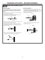
• The anti-tip wall bracket has a series of holes. Select 2
holes that match with the located studs. Make sure the
holes selected are on the center of the studs. Mark the
wall at these points.
• Mark an additional hole at each end of the bracket. If one
of the studs is closer to the end of the bracket, mark an
additional hole towards the center of the bracket.
• Drill 1/2” holes into the wall board at the locations
marked for the toggles to be mounted (not the stud
markings).
• Drill 3/16” holes into wooden studs where marked. If steel
stud construction, drill 1/2” holes into the studs where
marked. You will use 2 toggles with the metal studs.
Installation Instructions - Standard Installation
14
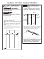
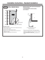
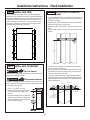
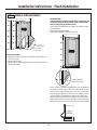
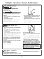
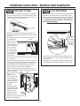
WARNING
Tip Over Hazard.
The unit is top-heavy and must be secured to prevent the
possibility of tipping forward.
AVERTISSEMENT
Risque de basculement
L’appareil ménager est beaucoup plus lourd en haut et il
faut le maintenir en place pour éviter la possibilité de son
basculement vers l’avant.
• The kit supplied with the unit contains 2 lag bolts and 4
toggles with bolts. The wall bracket will be attached to
the wall in 4 places.
• Measure the opening where the unit is to be installed.
Mark the center with a vertical line.
• Measure up 81 1/2” from the floor. Mark this point on the
wall.
• Using a level, draw a horizontal line on the wall at this
height.
• Locate at least 2 studs on the back wall. Mark these
points on the horizontal line.
• Place the bottom of the wall bracket with tabs on the
horizontal line. Align the center notch on the bracket
with the center line on the wall.
STEP 4 INSTALL ANTI-TIP BRACKET
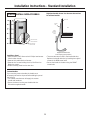
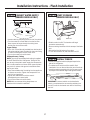
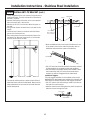
STEP 4 INSTALL ANTI-TIP BRACKET
(cont.)
Two Additional
Hole Locations at
Ends of Brackets
Center
Wall Bracket
Line On Wall
Wall Studs
Line on Wall
Center

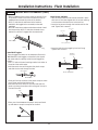
Install Screws and Bolts:
• Have someone hold the wall bracket centered in place
with each of the holes aligned with the correct opening in
the bracket and level with the horizontal line.
• Insert the lag screws through the bracket and into the
stud. Tighten with a wrench.
•
Insert the bolts into the toggle by hand until snug.
Tighten with a wrench.
Anti-Tip Wall Bracket
Bolt
Wall Toggle
Drywall or
Steel Stud
Install Wall Toggles:
The wall toggles and bolts can be ordered as Service Kit
#WR49X10193. Wall toggles are installed in the drywall
and metal studs for stability. Install the wall toggles as
follows:
• Drill 1/2” holes at the wall markings made in the holes at
the ends of the wall bracket.
• Hold the metal channel flat against the plastic straps
and slide the channel through the hole.
• Gently pull back at the ends of the plastic straps to make
the channel rest flush behind the wall.
• Hold the ends of the straps in one hand and slide the
plastic cap along the straps until the flange of the cap is
flush with the wall.
• Place your thumb between the plastic straps and bend
up and down to snap the straps off at the wall.
Installation Instructions - Standard Installation
15
Plastic Straps
Metal Channel
Wood Stud
Lag Screw
Anti-Tip Wall Bracket
Cap
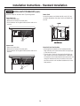
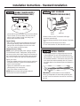
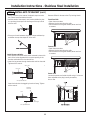
STEP 4 INSTALL ANTI-TIP BRACKET (cont.)

Installation Instructions - Standard Installation
16
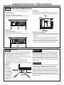
Remove Grilles for Access to Anti-Tip Locking Hooks
Fresh Food Unit
• Open the access door.
• Remove the 4 screws from the grille.
• Pull the bottom of the grille forward, down and out to
remove.
Freezer Unit
• Open the access door.
• Remove the 4 screws from the grille.
• Pull the bottom of the grille forward, down and out to
remove.
Power Cord
Locate the power cord inside the left cavity. If it has
not been adjusted so the plug is easily accessible, do
so now.
Move Unit into Final Position
• Move appliance toward its final installed location.
Align the tabs on the wall bracket with the openings
in the back of the unit.
• The unit has “L” bolts in the upper left and right cor-
ners inside of the access compartment. These bolts
will interlock with the wall bracket and secure the unit
using the washers and hair pin cotters in the hard-
ware kit once the unit has been leveled and is in the
final position.
STEP 4 INSTALL ANTI-TIP BRACKET (cont.)

17
Installation Instructions - Standard Installation
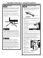
STEP 5 LEVEL UNIT
All models have 4-point leveling. The front is supported
by leveling legs; the rear is supported by adjustable
wheels. Both are accessible from the front of the unit.
• To level the back of the unit, turn the 7/16” hex nut
located above the front wheels. Turn clockwise
to raise or counterclockwise to lower the unit.
• For front leveling, use a 1-1/4” open-end wrench.
• Adjust height of unit to match installation cutout
opening 84-1/2”. The unit should be level and plumb
with cabinetry.
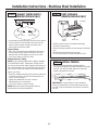
STEP 6 SECURE UNIT TO WALL
• The “L” rods can be found in the upper left and right
corners of the unit in the access compartment. Look
through the access compartment to make sure the
rods line up with the anti-tip bracket.
• There are 2 washers and a hair pin cotter per rod.
Remove the washers and hair pin cotter from the end
of the rod.
• Rotate and move the “L” rod into the slot in the anti-
tip bracket tab.
Once it is in the
slot, rotate the “L”
rod so the hook
portion is pointing
down. The holes
at the front end
of the rod should
be in a vertical
position. Do this
to both sides.
• Pull out on the end of the rod to make sure it is secure
in the bracket.
• Locate the hole on the rod that is closest to the unit. A
hair pin cotter will be put through this hole to secure
the rod. If this hole appears to be too far away for a
snug fit against the unit, add the washers one at a
time until the pin will fit tightly into the hole.
• Align the straight section of the pin with the hole
from the underside of the rod. Push the pin up until it
snaps into position.
Pliers may be used.
NOTE: The hair
pin cotter must be
vertical when this
step is completed to
ensure the “L” rod
is engaged in the
bracket.
• Check the rod for
tightness by pulling
forward. If the rod
moves, remove
the hair pin cotter
and place another
washer on the rod. Reinsert the pin.
• Replace the grille panel.
CAUTION
The rear leveling wheels and front leveling legs are
limited to a maximum height adjustment of 1”. If the
installation requires more than 84-1/2” height, the
installer should elevate the unit on a sheet of plywood
or runners. Cabinetry trim could also be added across
the top of the opening to shorten the opening. If you
attempt to raise the unit more than 1”, you will damage
the front leveling legs and the rear leveling wheels.
ATTENTION
Les roues de nivellement arrière et les pattes de
nivellement avant permettent un réglage maximal
de 25 mm (1 po). Si l’ouverture pour l’appareil
ménager a une hauteur supérieure à 2,15 m (84-1/2
po), l’installateur doit élever l’appareil ménager sur
une feuille de contre-plaqué ou des glissières. Il est
également possible d’ajouter des baguettes de finition
des placards sur le haut de l’ouverture afin de la
réduire. Lever l’appareil ménager de plus de 25 mm
(1 po) endommage les pattes de nivellement avant et
les roues de nivellement arrière.
“L” Rod
Wall Bracket
“L” Rod

Installation Instructions - Standard Installation
18
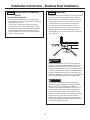
STEP 7 ADJUST DOOR SWING
NOTE: This appliance has a 3-position door stop. When
space does not allow the door to swing open fully to
115°, you may change the door swing to a 90° opening.
A 130° door swing is available for standard installation
only. Skip this step if door opening is satisfactory for
your installation situation.
• Open the hood to view the top hinge. Note the door
stop pin locations. The pin is factory-installed in the
115° position.
• Close the door. Use pliers to unscrew the door stop and
reinstall in the 90 degree or 130 degree position.
Pin Location
for 90°
Door Swing
Pin Location
for 130°
Door Swing
Pin Location
as Shipped
for 115°
Door Swing
STEP 8 INSTALL GRILLE PANEL
• Raise the access panel to the stop position.
• Loosen the screws on the side trim behind the frame.
Remove the bottom trim.
• Slide the panel over the metal baker panel and into
the trim.
• If necessary, tap with a wood block until the panel
slips under the top trim piece.
• Reassemble the bottom trim. Tighten the screws.
• Adjust the hinge spring to accommodate the panel
weight, if necessary.

Installation Instructions - Standard Installation
19
STEP 9 INSTALL FRAMED PANELS
• There are two sets of holes in the handle side trim.
Replace the handle side trim by installing the original
screws in the FRONT screw holes.
• Secure the handle to the door using the REAR screw
holes.
Use Rear Holes
to Secure Handle
Use Front Holes
to Secure Trim
Right hand models shown. Use the same instructions
for left hand models.
IF YOU ARE INSTALLING OVERLAY PANELS,
GO TO STEP 10A.
Install Door Panel:
• Open the door to 90°. Remove the 6 Phillips head screws
from the door handle.
• Remove the handle. Retain all screws.
• Remove the 6 screws holding the trim, lift off the trim.
Retain the screws.
• Slide the framed panel into the door trim.
Standard supplied handle shown
in 1/4” panel position.
Door
Door Trim
Handle
Trim

Installation Instructions - Standard Installation
20
STEP 9A INSTALL OVERLAY PANELS
• There are two sets of holes in the handle side trim.
Replace the handle side trim by installing the original
screws in the REAR screw holes.
• Secure the handle to the door using the FRONT
screw holes.
Custom Handles
If you are using custom handles, the handle must
be properly secured to the panel before sliding the panel
into the trim.
• The cabinet manufacturer will supply the custom
handle and hardware.
• Secure the door trim using new handle side trim.
Discard the supplied handle.
Right hand models shown. Use the same instructions
for left hand models.
Install Door Panel:
• Open the door to 90°. Remove the 6 Phillips head screws
from the door handle.
• Remove the handle. Retain all screws.
• Remove the 6 screws holding the trim, lift off the trim.
Retain the screws.
• Slide the overlay panel into the door trim.
Supplied handle shown
in the overlay panel position.
Door
Door Trim
Handle
Trim
Move
Forward
For 3/4"
Panel
Use Rear Holes
to Secure Trim
Use Front Holes
to Secure Handle
La page est en cours de chargement...
La page est en cours de chargement...
La page est en cours de chargement...
La page est en cours de chargement...
La page est en cours de chargement...
La page est en cours de chargement...
La page est en cours de chargement...
La page est en cours de chargement...
La page est en cours de chargement...
La page est en cours de chargement...
La page est en cours de chargement...
La page est en cours de chargement...
La page est en cours de chargement...
La page est en cours de chargement...
La page est en cours de chargement...
La page est en cours de chargement...
La page est en cours de chargement...
La page est en cours de chargement...
La page est en cours de chargement...
La page est en cours de chargement...
La page est en cours de chargement...
La page est en cours de chargement...
La page est en cours de chargement...
La page est en cours de chargement...
La page est en cours de chargement...
La page est en cours de chargement...
La page est en cours de chargement...
La page est en cours de chargement...
La page est en cours de chargement...
La page est en cours de chargement...
La page est en cours de chargement...
La page est en cours de chargement...
-
 1
1
-
 2
2
-
 3
3
-
 4
4
-
 5
5
-
 6
6
-
 7
7
-
 8
8
-
 9
9
-
 10
10
-
 11
11
-
 12
12
-
 13
13
-
 14
14
-
 15
15
-
 16
16
-
 17
17
-
 18
18
-
 19
19
-
 20
20
-
 21
21
-
 22
22
-
 23
23
-
 24
24
-
 25
25
-
 26
26
-
 27
27
-
 28
28
-
 29
29
-
 30
30
-
 31
31
-
 32
32
-
 33
33
-
 34
34
-
 35
35
-
 36
36
-
 37
37
-
 38
38
-
 39
39
-
 40
40
-
 41
41
-
 42
42
-
 43
43
-
 44
44
-
 45
45
-
 46
46
-
 47
47
-
 48
48
-
 49
49
-
 50
50
-
 51
51
-
 52
52


GE Monogram ZIF360NHRH Guide d'installation
- Catégorie
- Frigos
- Taper
- Guide d'installation
- Ce manuel convient également à
dans d''autres langues
Documents connexes


Autres documents
-
Monogram ZIRP360NHRH Guide d'installation
-
GE ZIC360NHRH Guide d'installation
-
GE CKLBLSFNW2 Guide d'installation
-
-
-
-
Ada Home Decor DCRW2032 Mode d'emploi
-
Liebherr HC1540 Guide d'installation
-
 Sandusky BQ10351372-09 Mode d'emploi
-
Dometic 3312271.XXX Refrigerator Ventilation Air Channel Guide d'installation
