Valor 1030CIK Le manuel du propriétaire
- Catégorie
- Cheminées
- Taper
- Le manuel du propriétaire
Ce manuel convient également à

1
4007385-01
© Copyright Miles Industries Ltd., 2019
Note: This kit must be installed
by a qualifi ed installer, service
agency or gas supplier at the time
of the heater installation. These
instructions are to be used in
conjunction with the fi replace
main installation instructions.
INSTALLER
Leave this manual
with the appliance.
CONSUMER
Retain this manual
for future reference.
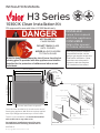
The 1030 Clean Installation Kit installs at the time of
framing the appliance. Wall fi nishes are then applied
over top of fl anges and butted up to 1030’s frame.
This kit is not intended to and cannot be installed
with an H3 trim or any other trim.
See appliance installation manual for more
information about finishing around this kit.
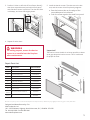
Overview
H3 1000
Upper panel
Left hand
panel
Right hand
panel
Lower panel
Right hand
door
Left hand
door
Removable panel
Barrier screen
Convection baffle
37-9/16” [954 mm]
33-5/16” [846 mm]
25” [635 mm]
34” [863 mm]
1-5/8” [42 mm]
7ULPȵXVKZLWKERWWRPRIDSSOLDQFH
1-5/8”
[41 mm]
1-1/8”
[29 mm]
HOT GLASS WILL
CAUSE BURNS.
DO NOT TOUCH GLASS
UNTIL COOLED.
NEVER ALLOW CHILDREN
TO TOUCH GLASS.
DANGER
!
A barrier designed to reduce the risk of burns from the hot
viewing glass is provided with this appliance and shall be
installed for the protection of children and other at-risk
individuals.
1030CIK Clean Installation Kit
CSA approved for use with Valor H3 1000 Models only
INSTALLATION MANUAL
H3 Series

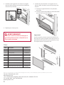
2
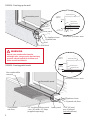
WARNING
Raised, non-combustibe hearths,
although safe, can get quite hot and may
present a burn hazard to children and
other at-risk individuals.
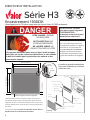
Section view, up the wall—detail
Lower panel
Removable panel
Finishing up the wall
Stud
Plywood base
Appliance base
:DOOȴQLVK
Combustible
VXEȵRRU
/RZHUSDQHO
3O\ZRRGVXEȵRRU
$SSOLDQFHEDVH
5HPRYDEOHSDQHO
1RQFRPEXVWLEOH
PDWHULDO
ȋLQVXODWLQJMicoreSDQHO
PLQȋZLGH[ȋGHHS
VXSSOLHGVHSDUDWHO\
1-5/8” [42 mm]
PD[WKLFNQHVV
(LQFOXGLQJ Micore
Lower panel
Removable panel
1-5/8”
[42 mm]
Front of
appliance
Plywood base
Appliance base
Lower
pan
el
1-5
5/8”
[42
2 mm
]
Plywood base
App
liance ba
se
Lower panel
Removable panel
1-1/8”
[29 mm]
Front of
appliance
Stud
Plywood base
Appliance base
Lower panel
Stu
d
Plywood b
ase
App
liance base
1030CIK - Finishing up the wall
1030CIK - Finishing with hearth
Section view, hearth—detail

3
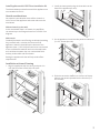
Install Appliance with 1030 Clean Installation Kit
The side brackets provided loose with the appliance are
not needed with this kit.
Hearth considerations
You need to know whether there will be a hearth or
not in front of the appliance and some rules must be
considered:
Without hearth (up the wall)
In the case where there is no hearth, the wall fi nish
can extend up to the fl ange at bottom of 1030CIK. See
diagram.
With hearth
Combustible hearths and fl ooring are allowed providing
they are fl ush with, or below, the bottom of the
appliance. Hearths raised above the bottom of the
appliance (max. 1-5/8” thick) will need to be constructed
of non-combustible material and use a thermal break
such as Micore between the non-combustible fi nish
and any combustible sub-fl oor below.
Raising the appliance further will help reduce fl oor
temperatures.
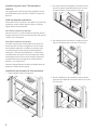
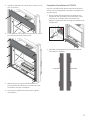
Installation at time of framing
1. Align the appliance with the cavity, and push it in
until the front face is fl ush with the studs.
2. Install the lower panel using the three bolts at the
base of the appliance (3 nuts).
3. On the appliance, install the side panels as indicated
(3 x 1/2" screws per side).
4. Slide the convection baffl e in to the front of the ap-
pliance, then attach upward into the liner box (3 x
3/8" screws).

4
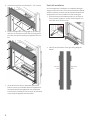
5. Install the top panel as indicated (3 x 1/2" screws).
6. Ensure the appliance is snug against the framing
and fi x it to the studs on each side (5 fi xing points
per side). Use wood screws (not supplied with this
kit).
7. Set aside the side doors, removable panel and
barrier screen to install later when the appliance’s
set-up and wall fi nish application are completed.
Continue the installation of the heater as indicated
in the manual supplied with the heater.
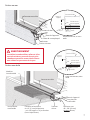
Finish kit installation
Once the appliance installation is completed with gas
supply connected, liners, fuel bed and window installed,
aeration checked, remote control paired and wall fi nish
completed, fi nish the installation of the framing kit.
1. Slide the bottom removable panel into the clips on
the horizontal supports on each side and push it in
until fl ush with the front trim.
2. Identify left hand door from right using diagram
below.
Right Hand
Door
Left Hand
Door

5
Code Description Part Number
1Top panel 4007174
2 Convection baffl e 4007175BY
3 Left hand side panel 4007161AZ
4 Right hand side panel 4007166AZ
5 Left hand side door 4007164AZ
6 Right hand side door 4007169AZ
7 Lower panel 4007171AZ
8Removable panel 4007172AZ
9 Barrier screen 4007095AZ
not
shown
#8 x 1/2 s/t screws black (9) 4004560
not
shown
#8 3/8 s/t screws countersunk
(3)
4007627
Repair Parts List
3. Position LH door to left side of front frame, identify
door slots top and bottom just behind front panel
and slide door locator in position. The door will slide
in sideways, and then slide slightly down.
4. Repeat for other door.
1
2
9
3
4
5
6
7
8
a
a
b
5. Install the barrier screen. The tabs rest at the bot-
tom, and the screen is held in place by magnets.
a. Rest the bottom tabs on the edge of the
removable panel as indicated.
a. Push the screen against the steel front panel.
Important!
The barrier screen should sit as low as possible, to leave
an air gap above the barrier screen. This is intentional
for proper air fl ow.
WARNING
For safety purpose, ensure the barrier
screen is re-installed ont the fi replace
after maintenance.
Designed and Manufactured by / for
Miles Industries Ltd.
190 – 2255 Dollarton Highway, North Vancouver, B.C., CANADA V7H 3B1
Tel. 604-984-3496 Fax 604-984-0246
www.valorfi replaces.com
Because our policy is one of constant development and improvement, details may vary slightly from those given in this publication.

6
Note : Ce kit doit être installé par
un installateur qualifi é, une agence
de service ou un fournisseur de
gaz au moment de l'installation
du foyer. Ces directives doivent
être utilisées conjointement avec
le guide d'installation de l'appareil.
L'Encastrement 1030 s'installe au foyer au moment
de l'encastrement dans la charpente et la position de
l'appareil est fi xe. Les matériaux de fi nition du mur sont
ensuite appliqués en couvrant le kit jusqu'au périmètre
du cadre.
Cet encastrement ne peut être installé avec d'autres
bordures du H3 ou toute autre bordure.
Concept
H3 1000
Panneau du haut
Montant
gauche
Montant
droit
Panneau du bas
Porte droite
Porte
gauche
Panneau amovible
Pare-étincelles
Déflecteur de
convection
37-9/16” [954 mm]
33-5/16” [846 mm]
25” [635 mm]
34” [863 mm]
1-5/8” [42 mm]
7ULPȵXVKZLWKERWWRPRIDSSOLDQFH
1-5/8”
[41 mm]
1-1/8”
[29 mm]
Encastrement 1030CIK
Homologué par la CSA pour usage avec les foyers Valor H3 1000 seulement
DIRECTIVES D'INSTALLATION
Série H3
INSTALLATEUR : Laissez
cette notice avec l’appareil.
CONSOMMATEUR :
Conservez cette notice pour
consultation ultérieure.
VITRE CHAUDE - RISQUE
DE BRÛLURES.
NE TOUCHEZ PAS UNE
VITRE NON REFROIDIE.
NE LAISSEZ JAMAIS UN
ENFANT TOUCHER LA VITRE.
L’écran pare-étincelles fourni avec ce foyer réduit le risque
de brûlure en cas de contact accidentel avec la vitre chaude
et doit être installé pour la protection des enfants et des
personnes à risques.
DANGER
!
Bordure égale au bas de l’appareil
Consultez le guide d'installation du
foyer pour les détails sur la finition
autour de ce kit.

7
AVERTISSEMENT
Les dalles incombustibles, même si elles
sont sécuritaires, peuvent devenir très
chaudes et peuvent causer des brûlures
aux enfants et personnes à risques.
Coupe transversale, au mur—
détail
Panneau du bas
Panneau amovible
Finition au mur
Linteau
Base de contreplaqué
Base de l’appareil
Finition du mur
Sous-plancher
combustible
Panneau
du bas
Sous-plancher
combustible
Base de l’appareil
Panneau amovible
Matériau
incombustible
Panneau isolant Micore
de 1/2” [13 mm] d’épaisseur
- min. 30” largeur x 10” profondeur
(fourni séparément)
Épaisseur max.
de 1-5/8” [42 mm]
(incluant Micore)
Panneau du bas
Panneau amovible
1-1/8”
[29 mm]
Devant de
l’appareil
Linteau
Sous-plancher
Base de l’appareil
Panneau du bas
Linteau
Sous-plancher
Base de l’appareil
Panneau du bas
Panneau amovible
1-1/8”
[29 mm]
Devant de
l’appareil
Linteau
Sous-plancher
Base de l’appareil
Panneau du bas
Linteau
Sous-plancher
Base de l
’ap
par
eil
Finition au mur
Finition avec dalle
Coupe transversale, dalle—
détail

8
Installez l'appareil avec l'Encastrement
1030CIK
Les supports des côtés fournis avec l'appareil ne sont
pas nécessaires pour installer le 1030CIK. Recyclez ou
jetez-les.
Dalle ou plancher protecteur
Vous devez savoir à ce point si une dalle ou un plancher
protecteur seront utilisés devant le foyer. Certaines
règles doivent être observées :
Sans dalle ou plancher protecteur
Dans le cas ou il n'y a pas de dalle ou plancher devant
le foyer, la fi nition du mur va jusqu'au rebord du bas du
1030CIF. Voir l'illustration.
Avec dalle ou plancher protecteur
Les dalles ou plancher combustibles sont permis en
autant que leur surface soit égale ou sous le niveau
de la base de l'appareil. Les dalles ou plancher dont
la surface est plus haute que la base de l'appareil -
maximum 1-5/8" (42 mm) d'épaisseur - doivent être
incombustibles et doivent inclure un panneau isolant
tel que Micore (non-fourni) entre la dalle ou plancher
incombustible et le sous-plancher combustible en-
dessous - voir l'illustration.
Soulever l'appareil aidera à réduire la température du
plancher ou dalle devant le foyer.
Installation au moment de l'encastrement
1. Placez l'appareil dans la charpente.
2. Sur la paroi du bas de l'appareil, enlevez les trois
écrous. Installez le panneau du bas sur les trois
chevilles fi letées et fi xez-le avec les écrous.
3. De chaque côté de l'ouverture, installez les mon-
tants en les fi xant avec six vis de 1/2" fournies.
4. Placez le défl ecteur de convection sous le rebord
supérieur de l'appareil puis fi xez-le avec trois vis de
3/8" fournies.

9
5. Installez le panneau du haut et fi xez-le avec trois vis
de 1/2" fournies.
6. Fixez l'appareil à la charpente en utilisant cinq vis à
bois (non-fournies) de chaque côté.
7. Mettez les portes, le panneau amovible et le
pare-étincelles de côté pour les installer une fois
l'installation du foyer complétée.
8. Continuez l'installation du foyer selon le guide
d'installation.
Complétez l'installation du 1030CIK
Une fois l'installation des pièces internes terminée et
a fi nition du mur appliquée, complétez l'installation de
l'encastrement.
1. Placez le panneau amovible sur les plaques hori-
zontales en bas de chaque côté et poussez-le vers
l'intérieur en l'insérant dans les attaches des
plaques. Le panneau doit être égal aux montants de
chaque côté.
2. Identifi ez la porte gauche de la droite à l'aide de
l'illustration ci-dessous.
Right Hand
Door
Left Hand
Door
Porte gauche Porte droite

10
Code Description Pièces n
o
1 Panneau du haut 4007174
2Défl ecteur de convection 4007175BY
3Montant gauche 4007161AZ
4Montant droit 4007166AZ
5Porte gauche 4007164AZ
6 Porte droite 4007169AZ
7 Panneau du bas 4007171AZ
8 Panneau amovible 4007172AZ
9 Pare-étincelles 4007095AZ
Vis noires #8 x 1/2 (9) 4004560
Vis tête fraisée plate - #8 x 3/8 (3) 4007627
Pièces
3. Installez la porte gauche en insérant ses onglets
dans les fentes situées juste derrière la façade du
montant tel qu'indiqué.
4. Répétez pour l'autre porte.
1
2
9
3
4
5
6
7
8
a
a
b
5. Installez le pare-étincelles. Les onglets vont en
bas et le pare-étincelles est tenu en place par des
aimants.
a. Posez les ong lets du bas sur le panneau
amovible.
b. Poussez le pare-étincelles au cadre de métal
pour le fi xer avec les aimants.
AVERTISSEMENT
Pour votre sécurité, assurez-vous que le
pare-étincelles soit bien réinstallé sur le
foyer après entretien.
Conçue et fabriquée par / pour
Miles Industries Ltd.
190 – 2255 Dollarton Highway, North Vancouver, BC, CANADA V7H 3B1
Tél. 604-984-3496 Téléc. 604-984-0246
www.foyervalor.com
Parce que nous favorisons une politique de développement continu, certains détails de la présente publication peuvent varier.
Important!
Une fois attaché, poussez le pare-étincelles vers le
bas jusqu'à ce que les onglets soient appuyés sur le
panneau amovible afi n qu'il y ait un espace en haut.
Cet espace assure la circulation d'air.
-
 1
1
-
 2
2
-
 3
3
-
 4
4
-
 5
5
-
 6
6
-
 7
7
-
 8
8
-
 9
9
-
 10
10


Valor 1030CIK Le manuel du propriétaire
- Catégorie
- Cheminées
- Taper
- Le manuel du propriétaire
- Ce manuel convient également à
dans d''autres langues
- English: Valor 1030CIK Owner's manual
Documents connexes
-
Valor BSK 1555 for 1555LFB Le manuel du propriétaire
-
-
-
-
-
-
-
-
-