
31-1000543 Rev. 0 10-20 GEA
English • Français • Español
TM
If you have questions, visit our website at: cafeappliances.com.
In Canada, visit: cafeappliances.ca
36” Built-In Bottom-Freezer
Refrigerators - CDB36
Installation
Instructions
BEFORE YOU BEGIN
Read these instructions completely and carefully.
• IMPORTANT – Save these instructions for local
inspector’s use. Observe all governing codes and
ordinances.
• Note to Installer – Be sure to leave these instructions
with the Consumer.
• Note to Consumer – Keep these instructions with
your Owner’s Manual for future reference.
If you received a damaged unit, you should immediately
contact your dealer or builder.
Skill Level – Installation of this unit requires basic
mechanical, carpentry and plumbing skills. Proper
installation is the responsibility of the installer. Product
failure due to improper installation is not covered under
the Café Warranty. See the Owner’s Manual for warranty
information.
WARNING
Tip Over Hazard. These appliances are top heavy, especially with any doors open,
and must be secured to prevent tipping forward which could result in death or serious injury. Read and follow the
entire installation instructions for securing the appliance with the anti-tip system.
WARNING
Fire or Explosion Hazard.
Keep flammable materials and vapors away from appliance. Failure to do so can result in fire, explosion, or death.
WARNING
To reduce the risk associated with choking, do not allow children under 3 years of age to have
access to small parts during the installation of this product.
CAUTION
Lifting Hazard This unit is very heavy. To reduce the risk of person injury during maneuvering
and installing this appliance, 3 people are required for proper installation.
CAUTION
Keep fingers out of the “pinch point” areas; clearances between the doors and between the doors
and cabinet are necessarily small. Be careful closing doors when children are in the area.
WARNING
Electrical Shock Hazard.
Plug into a grounded 3-prong outlet.
Do not remove the ground prong.
Do not use an adapter.
Immediately discontinue use of a damaged supply cord.
If the supply cord is damaged it must be replaced by a
qualified service professional with an authorized service
part from the manufacturer.
Do not use an extension cord with this appliance.
Failure to follow these instructions can result in death,
fire, or electrical shock.
Follow the instructions in the section Grounding the unit.
This appliance must be installed with a means in the
fixed house wiring or circuit breaker for disconnecting the
appliance from the electrical supply after installation.
READ AND SAVE THESE INSTRUCTIONS

2 31-1000543 Rev. 0
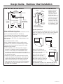
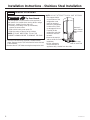
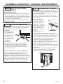
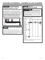
THE INSTALLATION SPACE
Water And Electrical Locations
Electrical and water supply must be located as shown.
The Cutout Depth Must Be 24” (60.96 cm)
The refrigerator will project forward, slightly beyond
adjacent cabinetry, depending on your installation.
Allow minimum 1/8” (0.32 cm) air gap between case
back & wall.
Cutout depth beneath a soffit:
When installed beneath a soffit, the soffit cannot
exceed the 24” (60.96 cm) installation depth shown.
The top case trim overlaps the bottom of the soffit.
Additional Specifications
• A 115 volt 60Hz., 15 or 20 amp power supply is
required. An individual properly grounded branch
circuit or circuit breaker is recommended. Install
a properly grounded 3-prong electrical receptacle
recessed into the back wall. Electrical must be located
on rear wall as shown.
• Water line can enter the opening through the floor
or back wall. Route SmartConnect
™
kit or 1/4” O.D.
copper tubing between the cold water line and the
water connection location. The tubing should be
long enough to extend to the front of the refrigerator.
Installation of an easily accessible shut-off valve in
the water line is required.
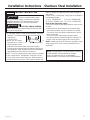
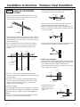
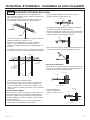
DIMENSIONS AND CLEARANCES
Product Clearances
These refrigerators are equipped with a 3-position door
stop. The factory set 115° door swing can be adjusted
to 90° if clearance to adjacent cabinets or walls is
restricted.
Allow 23 7/8” (60.64 cm)
minimum clearance for a full
130° door swing. Allow 15” (38.0
cm) for pan removal.
For a 90° door swing, allow
4 9/16” (11.59 cm) min.
clearance to a wall. If the 90°
door stop position is used, pan
access is maintained, but pan
removal is restricted.
See illustration on page 27 to determine door swing
interaction with adjacent cabinets or countertops.
36" Frame to
Frame Width
as Shipped
*84" From
Floor to
Top Frame
35"
Case Width
*83-1/2"
at
Rear
23-5/8"
Case Depth
Depth Including Handles:
28 1/16” Minimalist Style Models
28-1/2” Statement Style Models
* Shipping height. The
refrigerator can be
adjusted to fit into a
cutout that is 84-1/2
”
(214.63 cm) max.
height. Note that the top
case trim at the front is
1/2
” (1.27 cm) higher
and will overlap upper
cabinetry or soffit. Use
leveling legs and wheels
for a maximum 1
” (2.54
cm) height adjustment.
36-1/2”
90º Door Swing
23-5/8”
Behind
Frame
4-9/16” Min. Distance to Wall
90°
6"
Wall View
Electrical
Area
84-1/2" max
Finished
Opening
75" From
Floor to
Bottom
of Electrical Area
10"
24" Cutout Depth
35-1/2"
Finished Width
2-5/16"
5"
10"
10"
3-1/2" 3-1/2"
5"
3-1/2"
Water Supply
130° Door Swing
130°
23-7/8”
Minimum
to Wall
Design Guide - Stainless Steel Installation
16-7/8” Min.
to Wall
115°
115° Door Swing

31-1000543 Rev. 0 3
Design Guide - Stainless Steel Installation
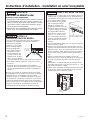
REFRIGERATOR LOCATION
• Do not install the refrigerator where the temperature
will go below 55°F (13°C). It will not run often
enough to maintain proper temperatures.
• Do not install the refrigerator where temperatures will
go above 100°F (37°C). It will not perform properly.
• Do not install the refrigerator in a location exposed to
water (rain, etc.) or direct sunlight.
• Install it on a floor strong enough to support it fully
loaded.
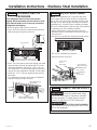
CUSTOMIZATION BASICS:
The unit comes with the Stainless Steel Handle on it.
Optional Handle Kits are availabe
Handle Accessory Kits
CXSB2H2PPBT - Brushed Black Stainless
CXSB2H2PPBZ - True Brushed Bronze
CXSB2H2PPCU - True Brushed Copper
*Optional Handles - When ordering this product, be
sure to use the model number associated with the
chosen handle.

4 31-1000543 Rev. 0
1/4"
1/2"
3/4"
1"
1-1/4"
1"
3/4" Overlay
Panel
(Nominal Size)
Stainless Steel
1/4"
1/2"
3/4"
2"
1-1/4"
1-1/2"
1-3/4"
3"
2-1/4"
2-1/2"
2-3/4"
1/4"
1/2"
3/4"
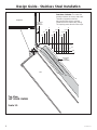
Door
23-7/8" From
Rear of
Refrigerator
1"
Refrigerator
Case
Trim
Top View
130° DOOR SWING
Scale 1:1
Frameless Cabinets: The case trim
overlaps cabinets at the top and sides.
Therefore, frameless cabinets
may require filler strips to prevent
interference with cabinet door swing.
The opening must allow for filler strips.
Design Guide - Stainless Steel Installation

31-1000543 Rev. 0 5
TOOLS REQUIRED
• Tinsnips to cut banding
• Stepladder
• Bucket
• Level
• Appliance Hand Truck
• Tubing cutter
• 7/16” open-end wrench
• #2 Phillips screwdriver
• Drill and appropriate bits
• 5/16”, 7/16” socket
• Safety glasses
• 1-1/4” open end wrench
• Pliers
• 1/4” ratchet
HARDWARE SUPPLIED
• Water filter bypass plug
• Anti-Tip brackets
• 1/4” nut and ferrule
MATERIALS REQUIRED
• 35” (88.9 cm) long 2x4 for Anti-Tip support
• 1/4” copper water line tubing or SmartConnect
™
Refrigerator Tubing kits
• Water shut-off valve
• Custom panels for fresh food door, freezer drawer and
grille panel
• Screws to secure refrigerator to cabinetry.
• Stick-on hook and loop fastener strips for
1/4” side panels
FLOORING
For proper installation, this refrigerator must be placed
on a level surface of hard material that is at the same
height as the rest of the flooring. This surface should be
strong enough to support a fully loaded refrigerator, or
approximately 1,200 lbs. (544.31 cm).
NOTE: Protect the finish of the flooring. Cut a large
section of the cardboard carton and place under the
refrigerator where you are working.
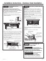
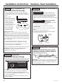
Installation Instructions - Stainless Steel Installation
GROUNDING THE REFRIGERATOR
WARNING
Electrical Shock Hazard.
Failure to follow these instructions can result in death,
fire, or electrical shock.
The power cord of this appliance is equipped with a
3-prong (grounding) plug which mates with a standard
3-prong (grounding) wall receptacle to minimize the
possibility of electric shock hazard from this appliance.
Have the wall outlet and circuit checked by a qualified
electrician to make sure the outlet is properly grounded.
Where a standard 2-prong wall outlet is encountered, it
is your personal responsibility and obligation to have it
replaced with a properly grounded 3-prong wall outlet.
DO NOT, UNDER
ANY CIRCUMSTANCES,
CUT OR REMOVE
THE THIRD (GROUND) PRONG
FROM THE POWER CORD.
DO NOT USE AN ADAPTER PLUG TO
CONNECT
THE REFRIGERATOR TO A 2-PRONG
OUTLET.
DO NOT USE AN EXTENSION CORD WITH THIS
APPLIANCE.

6 31-1000543 Rev. 0
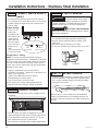
• The unit is secured to the skid with 4 slotted tie-down
straps. Remove the six 7/16” bolts from the base channels
in the tie-downs.
• Remove the six 7/16” bolts securing the straps to the skid.
NOTE: DO NOT ATTEMPT TO ROLL UNIT OFF SKID.
• The support blocks
on the bottom of the
refrigeration case
must be removed
before the refrigerator
is taken off the skid
or damage will occur.
Carefully tilt the
refrigerator and slide
the blocks out from
beneath.
• Remove the toekick
and set aside for final
installation.
• Lift the refrigerator
off the skid with an
appliance dolly. Handle from the sides.
Installation Instructions - Stainless Steel Installation
WARNING
Tip Over Hazard.
The refrigerator is much heavier at the top than at
the bottom—be careful when moving. When using a
hand truck, handle from the side only.
• Carefully cut banding at the top and bottom,
remove the outer carton.
• Slide out the back corner posts (2).
• Slide the carton off the top of the cabinet.
NOTE: IT IS NOT NECESSARY TO LAY THE
CABINET DOWN IN ORDER TO REMOVE THE SKID!
STEP 1 REMOVE PACKAGING
Remove 2 strap
bolts on each side
Remove 5
base channel
bolts on each
side

31-1000543 Rev. 0 7
STEP 2 INSTALL WATER LINE
• A cold water supply is required for automatic icemaker
operation. The water pressure must be between 40
and 120 p.s.i.
(275-827 kPa).
• Route 1/4” OD copper or
SmartConnect
™
plastic
tubing between house
cold water line and the water connection location.
• Tubing should be long enough to extend to the front of
the refrigerator. Allow enough tubing to accommodate
bend leading into the water line connection.
NOTE: The only Cafe-approved plastic tubing is supplied
in the SmartConnect
™
Refrigerator Tubing kits. Do not
use any other plastic water supply line because the line
is under pressure at all times. Other types of plastic may
crack or rupture with age and cause water damage to
your home.
SmartConnect
™
Refrigerator Tubing Kits are available in
the following lengths:
2’ (.6 m) - WX08X10002 8’ (2.4 m) - WX08X10006
15’ (4.6 m) - WX08X1 0015 25’ (7.6 m) - WX08X10025
Shut off the main water supply.
Turn on the nearest faucet long enough to clear the line
of water.
• Install a shut-off valve between the icemaker water
valve and cold water pipe in a basement or cabinet.
The shut-off valve should be located where it will be
easily accessible.
• Turn on the main water supply and flush debris.
Run about a quart of water through the tubing into a
bucket. Shut off water supply at the shut-off valve.
NOTE: Saddle type shut-off valves are included in many
water supply kits, but are not recommended for this
application.
Floor
Waterline Tubing
Installation Instructions - Stainless Steel Installation
WARNING
Connect to potable water supply
only. A cold water supply is required for automatic
icemaker operation. The water pressure must be
between 40 and 120 psi (275-827 kilopascals).
WARNING
ELECTRIC SHOCK HAZARD
Attach tubing clamp using existing hole only. DO NOT
drill into the refrigerator.
NOTE: Commonwealth of Massachusetts Plumbing
Codes 248CMR shall be adhered to. Saddle
valves are illegal and use is not permitted in
Massachusetts. Consult with your licensed plumber.

8 31-1000543 Rev. 0
Installation Instructions - Stainless Steel Installation
STEP 3 INSTALL SIDE PANELS
Skip this step when not using side panels.
If you are using 1/4” (0.63 cm) side panels, they should
be inserted into the case trim. Fasten the panels to the
refrigerator with stick-on hook and loop fastener strips
before setting refrigerator in place.
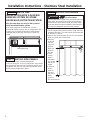
STEP 4 ANTI-TIP PROCEDURE
WARNING
Tip Over Hazard.
These refrigerators are top heavy, especially with any
doors open, and must be secured to prevent tipping
forward which could result in death or serious injury.
Read and follow the entire installation instructions for
securing the refrigerator with the anti-tip system.
• The kit supplied with the unit contains 2 lag bolts and
4 toggles with bolts. The wall bracket will be attached
to the wall in 4 places.
• Measure the opening where the unit is to be installed.
Mark the center with a vertical line.
• Measure
up 81 1/2”
(207.01
cm) from
the floor.
Mark this
point on
the wall.
• Using
a level,
draw a
horizontal
line on the
wall at this
height.
• Locate at
least 2
studs on
the back
wall. Mark
these
points on
the horizontal line.
STEP 2A WATER LINE
INSTALLATION WITH A REVERSE
OSMOSIS SYSTEM OR OTHER
HOUSEHOLD FILTRATION SYSTEM
Skip this step when not using an RO System or
other household filtration system
If the water supply to the refrigerator is from a
household filtration system, use the refrigerator’s filter
bypass plug. Using the refrigerator’s water filtration
cartridge with the RO filter can result in hollow ice
cubes.
Filter Bypass Plug

31-1000543 Rev. 0 9
Installation Instructions - Stainless Steel Installation
STEP 4 ANTI-TIP PROCEDURE
(CONT)
• Place the bottom of the wall bracket with tabs on the
horizontal line. Align the center notch on the bracket
with the center line on the wall.
• The anti-tip wall bracket has a series of holes. Select 2
holes that match with the located studs. Make sure the
holes selected are on the center of the studs. Mark the
wall at these points.
• Mark an additional hole at each end of the bracket. If
one of the studs is closer to the end of the bracket,
mark an additional hole towards the center of the
bracket.
• Drill 1/2” (1.27 cm) holes into the wall board at the
locations marked for the toggles to be mounted (not the
stud markings).
• Drill 3/16” (0.47 cm) holes into wooden studs where
marked. If steel stud construction, drill 1/2” (1.27 cm)
holes into the studs where marked. You will use 2
toggles with the metal studs.
Install Wall Toggles:
The wall toggles and bolts can be ordered as Service Kit
#WR49X10193. Wall toggles are installed in the drywall
and metal studs for stability. Install the wall toggles as
follows:
• Drill 1/2” (1.27 cm) holes at the wall markings made in
the holes at the ends of the wall bracket.
• Hold the metal channel flat against the plastic straps
and slide the channel through the hole.
• Gently pull back at the ends of the plastic straps to
make the channel rest flush behind the wall.
• Hold the ends of the straps in one hand and slide the
plastic cap along the straps until the flange of the cap is
flush with the wall.
• Place your thumb between the plastic straps and bend
up and down to snap the straps off at the wall.
Install Screws and Bolts:
• Have someone hold the wall bracket centered in place
with each of the holes aligned with the correct opening
in the bracket and level with the horizontal line.
• Insert the lag screws through the bracket and into the
stud. Tighten with a wrench.
• Insert the bolts into the
toggle by hand until
snug. Tighten with a
wrench.
Line on Wall
Center
Two Additional
Hole Locations at
Ends of Brackets
Center
Wall Bracket
Line On Wall
Wall Studs
Plastic Straps
Metal Channel
Cap
Wood Stud
Lag Screw
Anti-Tip Wall Bracket
Anti-Tip Wall Bracket
Bolt
Wall To
ggle
Drywall or
Steel Stud

10 31-1000543 Rev. 0
Installation Instructions - Stainless Steel Installation
STEP 4 ANTI-TIP PROCEDURE
(CONT)
Connect Power Cord:
• Before pushing the refrigerator into the opening, plug
the power cord into the receptacle. Open the grille
panel and reach into the opening at the back to grasp
the power cord. Pull the power cord into the opening
as you push the refrigerator back.
• Gently push refrigerator into the opening with hands
against front corners.
STEP 5 LEVEL REFRIGERATOR
All models have 4-point leveling. The front is supported
by leveling legs, the rear is supported by adjustable
wheels. Both are accessible from the front of the
refrigerator.
• To level the back of
the refrigerator, turn
the 7/16” hex nut
located above the
front wheels. Turn
clockwise to raise
or counterclockwise
to lower the
refrigerator.
• For front leveling, use a 1-1/4” open-end wrench.
• Adjust height of refrigerator to match installation
cutout opening 83-1/2” (212.09 cm) to 84-1/2”
(10.16 cm). The refrigerator should be level and
plumb with cabinetry.
The rear leveling wheels and front leveling legs are
limited to a maximum height adjustment of 1” (2.54
cm). If the installation requires more than 84-1/2”
(214.63 cm) height, the installer should elevate the
refrigerator on a sheet of plywood or runners. Cabinetry
trim could also be added across the top of the opening
to shorten the opening. If you attempt to raise the
refrigerator more than 1” (2.54 cm), you will damage
the front leveling legs and the rear leveling wheels.
STEP 6 SECURE UNIT TO WALL
• The “L” rod can be found in the upper left corner of
the unit in the access compartment. Look through the
access compartment to make sure the rod lines up
with the anti-tip bracket.
• There are 2 washers and a hair pin cotter with the
rod. Remove the washers and hair pin cotter from the
end of the rod.
• Rotate and move the
“L” rod into the slot in
the anti-tip bracket tab.
Once it is in the slot,
rotate the “L” rod so the
hook portion is pointing
down. The holes at the
front end of the rod
should be in a vertical
position.
• Pull out on the end of
the rod to make sure it is secure in the bracket.
• Locate the hole on the rod that is closest to the unit. A
hair pin cotter will be put through this hole to secure
the rod. If this hole appears to be too far away for a
snug fit against the unit, add the washers one at a
time until the pin will fit tightly into the hole.
• Align the straight section of the pin with the hole
from the underside of the rod. Push the pin up until it
snaps into position. Pliers may be used.
NOTE: The hair pin cotter must be vertical when this
step is completed to ensure the “L” rod is engaged in
the bracket.
• Check the rod for tightness by pulling forward. If the
rod moves, remove the hair pin cotter and place
another washer on the rod. Reinsert the pin.

31-1000543 Rev. 0 11
STEP 8 ADJUST DOOR SWING
NOTE: This refrigerator has a 3-position door stop.
When space does not allow the door to swing open
fully to 115°, you may change the door swing to a 90°
opening. A 130° door swing is available for standard
installation only. If used for flush installation, damage
will occur to wood panels. Skip this step if door opening
is satisfactory for your installation situation.
• Lift the grille panel to access the wire cover trim.
• Remove screws on both sides of the wire cover trim
and rotate off.
• Use pliers to unscrew door stop and reinstall into the
90° or 130° (standard only) position.
• Reinstall the wire cover trim.
STEP 9 CONNECT WATER SUPPLY
Pin Location
for 90°
Door Swing
Pin Location for
130° Door Swing
(Standard Only)
Pin Location
as Shipped for
115°
Door Swing
Installation Instructions - Stainless Steel Installation
STEP 7 ALTERNATE ANTI-TIP
PROCEDURE
The refrigerator must be secured to prevent
tipping. When the anti-tip bracket cannot be used,
this alternate method can be used to prevent the
refrigerator from tipping.
• Raise the grille panel to access case trim.
• Use a 3/16” bit to drill four evenly spaced clearance
holes through the metal top case trim.
• Use a 1/16” bit to drill to pilot holes through the metal
clearance holes and into the wood soffit. The holes
should be centered in the soffit or a 3/4” (1.90 cm)
min. wood brace. The brace spanning the enclosure
must be securely fastened to cabinets on both sides.
• Install four, 1-1/2” (3.81 cm) drywall screws into the
pilot holes.
• If no soffit above the unit, drill screws into adjacent
cabinets through the side case trim.
Top Case Trim
Install four 1-1/2” drywall screws through
trim and into soffit or 3/4” min. wood brace
3/4” Min.
Side View Top
Case Trim
Raise grille panel to
stop position
Drive screws through case
trim into adjacent cabinets
Remove grille screws
WARNING
Connect to potable water supply
only. A cold water supply is required for automatic
icemaker operation. The water pressure must be
between 40 and 120 psi (275-827 kilopascals).
WARNING
ELECTRIC SHOCK HAZARD
Attach tubing clamp using existing hole only. DO NOT
drill into the refrigerator.

12 31-1000543 Rev. 0
STEP 9 CONNECT WATER SUPPLY
(cont.)
• Locate and bring tubing to the front of the cabinet.
• Turn the water on to flush debris from line. Run about
a quart of water through tubing into a bucket, then
shut off water.
Copper Tubing:
• Slip a 1/4” nut
and ferrule
(provided) over
both ends of the
copper tubing.
Insert tube into
the union fitting
on the unit and
tighten nut to
union.
• Turn on the water
to check for leaks.
SmartConnect
™
Tubing:
NOTE: The only Cafe-approved plastic tubing is
supplied in the SmartConnect
™
Refrigerator Tubing kits.
Do not use any other plastic water supply line because
the line is under pressure at all times. Other types of
plastic may crack or rupture with age and cause water
damage to your home.
• Insert the molded end of the tubing into the
refrigerator connection. Tighten the compression nut
until it is just hand tight.
• Tighten one additional turn with a wrench.
Overtightening can cause leaks!
• Turn on the water to check for leaks.
NOTE: Make sure excess tubing length does not
interfere with drawer closing or toekick installation.
Refrigerator
Water Supply
House
Water Supply
Installation Instructions - Stainless Steel Installation
STEP 10 CONNECT POWER
• Check to be sure the power cord is plugged into the
receptacle.
• Check to make sure power to refrigerator is on by
opening refrigerator door to see if interior lights are on.
• The temperature controls are preset at 37°F for the
fresh food section and 0°F for the freezer.
• Allow 24 hours to stabilize before making adjustments.
Electrical Outlet
STEP 12 INSTALL TOEKICK
• Locate the supplied toekick (shipped taped to the side
of the refrigerator). Install the toekick assembly with
the 2 screws provided, adjust to the desired height
and tighten the screws.
IMPORTANT: A custom toekick can be installed to
match or complement the surrounding cabinetry but
can NOT cover the horizontal vent slots of the factory
toe kick.
STEP 11 START ICEMAKER
• The icemaker will begin operation automatically.
• Be sure nothing interferes with the sweep of the
feeler arm.
• Discard the first full bucket of ice cubes.
• To turn the icemaker off, slide the switch to O (OFF).
Icemaker
Feeler Arm
Power
Switch
WARNING
Connect to potable water supply
only. A cold water supply is required for automatic
icemaker operation. The water pressure must be
between 40 and 120 psi (275-827 kilopascals).
WARNING
ELECTRIC SHOCK HAZARD
Attach tubing clamp using existing hole only. DO NOT
drill into the refrigerator.

31-1000543 Rev. 0 13
Notes

14 31-1000543 Rev. 0
NOTE: While performing installations described in this book,
safety glasses or goggles should be worn.
NOTE: Product improvement is a continuing endeavor at
Cafe Appliances. Therefore, materials, appearance and
specifications are subject to change without notice.
Printed in United States
TM

31-1000543 Rev. 0 10-20 GEA
TM
Si vous avez des questions, visitez notre site Web à: cafeappliances.com.
Au Canada, visitez: cafeappliances.ca
Réfrigérateurs encastrables à
congélateur en bas de 36" - CDB36
Instructions
d’installation
AVANT DE COMMENCER
Veuillez lire toutes ces instructions attentivement.
• IMPORTANT – Conservez ces instructions à l’usage de
l’inspecteur local. Observez tous les codes et décrets en vigueur.
•
Note à l’installateur – Assurez-vous de laisser ces
instructions au consommateur.
•
Note au consommateur - Conservez ces instructions
avec votre manuel d’utilisation pour
consultation ultérieure.
Si vous avez reçu un appareil endommagé, veuillez
communiquer immédiatement avec votre revendeur ou votre
entrepreneur.
Niveau de compétence – L’installation de cet appareil exige
des compétences de base en mécanique, menuiserie et plomberie.
La responsabilité d’une installation adéquate relève de l’installateur.
La garantie Cafe ne couvre pas les défectuosités du produit
causées par une installation inadéquate. Consultez le manuel
d’utilisation pour des renseignements sur la garantie.
AVERTISSEMENT
Risque de basculement.
Ces électroménagers sont lourds du haut, notamment lorsqu’une porte est ouverte, de sorte qu’ils doivent être fixés pour
prévenir un basculement vers l’avant susceptible d’occasionner des blessures graves ou la mort. Lisez et observez la totalité des
instructions d’installation pour connaître la façon de fixer l’électroménager sur le dispositif antibasculement.
AVERTISSEMENT
Risque d’incendie ou d’explosion.
Gardez les matériaux et les vapeurs inflammables à l’écart de l’appareil. L’omission de prendre cette précaution peut entraîner un
incendie, une explosion ou la mort.
AVERTISSEMENT
Pour réduire le risque d’étouffement pendant l’installation de ce produit, ne pas laisser les petites pièces
à la portée des enfants âgés de moins de 3 ans.
AVERTISSEMENT
Risque lié à la manipulation d’un objet lourd
Cet appareil est très lourd. Afin de réduire le risque de blessure pendant la manipulation et l’installation de cet électroménager, la
participation de 3 personnes est nécessaire à l’exécution d’une installation correcte.
AVERTISSEMENT
Gardez vos doigts éloignés des points de pincement. Les espaces entre les portes et ceux entre les
portes et l’armoire sont particulièrement restreints. Soyez prudent lorsque vous fermez les portes en présence d’enfants.
AVERTISSEMENT
Risque d’électrocution.
Branchez l’appareil dans une prise à 3 broches mise à la terre.
N’enlevez pas la broche de mise à la terre.
N’utilisez pas un adaptateur.
Cessez immédiatement l’utilisation d’un cordon électrique
endommagé. Si le cordon électrique est endommagé, son
remplacement doit être exécuté par un technicien en réparation
qualifié au moyen d’un cordon de rechange autorisé par le fabricant.
N’utilisez pas un cordon de rallonge avec cet électroménager.
Le non-respect de ces instructions peut occasionner un décès,
un incendie ou un choc électrique
Suivez les instructions de la section Mise à la terre de l’appareil.
Le circuit électrique auquel cet électroménager sera raccordé
doit comporter un disjoncteur ou un autre dispositif permettant de
couper l’alimentation électrique à l’appareil après l’installation.
LISEZ ET CONSERVEZ CES INSTRUCTIONS

2 31-1000543 Rev. 0
Guide de conception – Installation en acier inoxydable
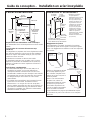
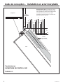
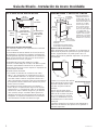
L’ESPACE D’INSTALLATION
Emplacements des alimentations d’eau et électrique.
Les alimentations d’eau et électrique doivent se situer comme
illustré.
La profondeur de l’ouverture doit mesurer 24 po
(60,96 cm)
Le réfrigérateur se projettera vers l’avant, légèrement au-delà
des armoires adjacentes, selon le type de votre installation.
Allouez un espace d’air minimal de 1/8 po (0,32 cm) entre
l’arrière du caisson et le mur.
Profondeur de l’ouverture en dessous d’un soffite :
Si l’installation s’effectue sous un soffite, celui-ci ne peut
dépasser la profondeur de l’installation de 24” (60.96 cm)
illustrée. La garniture de caisson supérieure chevauche le
bas du soffite.
Spécifications supplémentaires
• Une alimentation électrique de 115 volts, 60Hz, 15 ou
20 ampères est requise. Un circuit de dérivation ou
un disjoncteur distinct correctement mis à la terre sont
recommandés. Installez une prise électrique à trois alvéoles
correctement mise à la terre encastrée dans le mur arrière.
Le câblage électrique doit se situer sur le mur arrière
comme illustré.
• La conduite d’eau peut pénétrer dans l’ouverture à travers
le plancher ou le mur arrière. Acheminez la trousse
SmartConnect™ ou un tuyau de cuivre de 1/4 po (D.E.)
entre la conduite d’eau froide et le lieu du raccord d’eau. Le
tuyau doit être suffisamment long pour atteindre le devant
de l’appareil. L’installation d’un robinet de sectionnement
aisément accessible est requise.
DIMENSIONS ET DÉGAGEMENTS
Dégagements du produit
Ces réfrigérateurs sont dotés d’une butée à 3 positions.
L’ouverture de porte de 115° réglée à l’usine peut s’ajuster
à 90° si le dégagement aux armoires ou aux murs adjacents
est restreint.
Allouez un dégagement minimal
de 23 7/8 po (60,64 cm) pour
une ouverture complète à 130°.
Allouez 15 po (38,1 cm) pour le
retrait du plateau.
Dans le cas d’une ouverture
de porte à 90°, allouez un
dégagement minimal de 4 9/16
po (11,59 cm) jusqu’au mur.
Si l’on utilise la position à 90°,
l’accès au plateau est maintenu
mais son retrait est restreint.
Voyez l’illustration à la page 22 pour déterminer l’impact
de l’ouverture de porte sur les armoires ou les comptoirs
adjacents.
36" Largeur
cadre à cadre
à la livraison
*84”
du plancher
au cadre
supérieur
35” Largeur
du caisson
*83-1/2"
à l’arrière
23-5/8"
Profondeur
du caisson
Profondeur plus poignées :
28-1/16" Modèles de style minimaliste
28-1/2" Modèles de st
y
le de déclaration
* Hauteur à la livraison.
On peut ajuster le
réfrigérateur pour le placer
dans une ouverture de
84 ½ po (214,63 cm) de
hauteur max. Notez que
la garniture de caisson
supérieure sur le devant
est plus haute de 1/2
po (1,27 cm) et qu’elle
chevauchera l’armoire
supérieure ou le soffite.
Utilisez les pieds de
nivellement et les roulettes
pour un ajustement
maximal en hauteur de 1
po (2,54 cm).
Ouverture
de porte à 90°
90°
23 7/8”
derrière
le cadre
36-3/4”
4” Distance min. au mur
6"
Vue du mur
Zone
électrique
Ouverture
finie max.
84 ½”
75” du plancher
jusqu’au bas
de la zone
électrique
10"
Profondeur de
l’ouverture 24”
35-1/2"
Largeur finie
2-5/16"
5"
10"
10"
3-1/2" 3-1/2"
5"
3
-
1/2
"
Alimentation d’eau
Ouverture
de porte à 130º
130º
25”
minimum
au mur
Ouverture de porte à 115°
16 7/8 po
min. au
mur
115°

31-1000543 Rev. 0 3
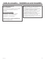
Guide de conception – Installation en acier inoxydable
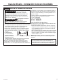
EMPLACEMENT DU RÉFRIGÉRATEUR
• N’installez pas le réfrigérateur à un endroit où la
température peut descendre en dessous de 55 °F (13
°C). L’appareil ne fonctionnera pas suffisamment souvent
pour maintenir les températures appropriées.
• N’installez pas le réfrigérateur/congélateur à un endroit
où la température monter au-delà de 100 °F (37 °C).
L’appareil ne fonctionnera pas correctement.
• N’installez pas le réfrigérateur dans un endroit exposé à
l’eau (pluie, etc.) ou aux rayons directs du soleil.
• À cet endroit, le plancher doit pouvoir supporter le poids
du réfrigérateur pleinement chargé.
Principes de base de la
personnalisation:
L’unité est livrée avec la poignée en acier inoxydable
dessus. Des kits de poignées en option sont
disponibles.
Kits d’accessoires de poignée
CXSB2H2PPBT - Acier inoxydable noir brossé
CXSB2H2PPBZ - Bronze véritable brossé
CXSB2H2PPCU - Vrai cuivre brossé
*Poignées en option - Lors de la commande de ce
produit, assurez-vous d’utiliser le numéro de modèle
associé à la poignée choisie.

4 31-1000543 Rev. 0
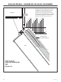
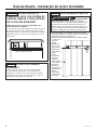
Guide de conception – Installation en acier inoxydable
1/4"
1/2"
3/4"
1"
1-1/4"
1"
Panneau
de recouvrement
3/4” (dim. nominale)
Acier inoxydable
1/4"
1/2"
3/4"
2"
1-1/4"
1-1/2"
1-3/4"
3"
2-1/4"
2-1/2"
2-3/4"
1/4"
1/2"
3/4"
Porte
23 7/8”
depuis l’arrière
du réfrigérateur
1"
Réfrigérateur
Garniture de caisson
Vue de dessus
OUVERTURE DE PORTE À 130º
Échelle 1:1
Armoires sans cadre: La garniture de caisson
chevauche les armoires dans le haut et les côtés.
Par conséquent, les armoires sans cadre peuvent
nécessiter des fourrures pour ne pas gêner
l’ouverture de la porte d’armoire. L’ouverture doit
permettre la pose de fourrures.

31-1000543 Rev. 0 5
Instructions d’installation - Installation en acier inoxydable
MISE À LA TERRE DU
RÉFRIGÉRATEUR
AVERTISSEMENT
Risque de choc électrique.
Le non-respect de ces instructions peut entraîner des risques
d’incendies, des chocs électriques ou la mort.
Le cordon d’alimentation de cet appareil est équipé d’une
fiche à trois broches (pour une mise à la terre) qui s’adapte à
la prise de courant standard à 3 broches (pour une mise à la
terre) pour minimiser les risques de chocs électriques par cet
appareil.
Faites vérifier la prise murale et le circuit électrique par
un électricien qualifié pour s’assurer que le système est
correctement mis à la terre.
Dans le cas d’une prise biphasée, l’installateur a la
responsabilité et l’obligation de la remplacer par une prise
triphasée correctement mise à la terre.
NE COUPEZ PAS OU N’ENLEVEZ PAS, SOUS AUCUN
PRÉTEXTE, LA TROISIÈME BROCHE DE MISE À LA
TERRE DU CORDON D’ALIMENTATION.
N’UTILISEZ PAS D’ADAPTATEUR POUR BRANCHER LE
RÉFRIGÉRATEUR À UNE PRISE BIPHASÉE.
N’UTILISEZ PAS DE RALLONGE AVEC CET APPAREIL.
OUTILS REQUIS
• Cisaille pour couper le cerclage
• Escabeau
• Seau
• Niveau
• Diable pour électroménagers
• Coupe-tuyau
• Clé ouverte 7/16 po
• Tournevis à tête cruciforme no 2
• Perceuse et forets appropriés
• Douille 5/16, 7/16 po
• Lunettes de protection
• Clé ouverte 1 1/4 po
• Pince
• Cliquet 1/4 po
QUINCAILLERIE FOURNIE
• Bouchon de dérivation de filtre
• Ferrures antibasculement
• Écrou et bague 1/4 po
MATÉRIEL REQUIS
• Support antibasculement 2x4, 35 po long
• Tuyau de cuivre 1/4 po pour conduite d’eau ou trousse
SmartConnect™ pour réfrigérateur
• Robinet de sectionnement
• Panneaux personnalisés, panneaux de tiroir congélateur et
de grille
• Vis pour fixer le réfrigérateur aux armoires
• Ruban autoagrippant adhésif pour panneaux latéraux 1/4 po
(0,63 cm)
PLANCHER
Une installation correcte exige que le réfrigérateur soit
placé sur la surface d’un matériau dur de niveau et de la
même hauteur que le reste du plancher. Cette surface doit
être suffisamment robuste pour supporter un réfrigérateur
pleinement chargé, ou environ 1200 lb. (544,31 kg)
REMARQUE: Protégez le fini du plancher. Découpez une
grande section de carton et placez-la sous le réfrigérateur à
l’endroit où vous travaillez.

6 31-1000543 Rev. 0
Instructions d’installation - Installation en acier inoxydable
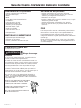
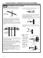
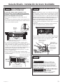
ÉTAPE 1 RETRAIT DE L’EMBALLAGE
AVERTISSEMENT
Risque de basculement
Le réfrigérateur est beaucoup plus lourd en haut qu’en bas. Il faut
être prudent lors des déplacements. Si un diable est utilisé, il faut
soulever le réfrigérateur sur le côté seulement.
• Couper avec précaution le cerclage dans le haut et le bas,
retirez le carton extérieur.
• Retirez les montants d’angle arrière (2) en les glissant.
• En le glissant, retirez le carton du haut de l’appareil.
REMARQUE : IL N’EST PAS NÉCESSAIRE DE DÉPOSER
L’APPAREIL POUR RETIRER LE PATIN!
• L’appareil est fixé sur le patin à l’aide de 4 brides d’arrimage
à fente. Retirez les six boulons 7/16 po des profilés de base
dans les brides.
• Retirez les six boulons 7/16 po qui fixent les brides sur le
patin.
REMARQUE : NE TENTEZ PAS DE ROULER L’APPAREIL
HORS DU PATIN.
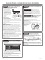
• Les blocs de support dans
le bas du compartiment de
réfrigération doivent être retirés
avant que le réfrigérateur
puisse être dégagé du
patin, sinon il y a risque
d’endommagement. Penchez
avec précaution le réfrigérateur
et glissez les blocs vers
l’extérieur depuis le dessous.
• Retirez le coup-de-pied
et mettez-le de côté pour
l’installation finale.
• Soulevez le réfrigérateur du
patin à l’aide d’un diable pour
électroménager. Manipulez
depuis les côtés.
Retirez les 2
boulons de bride
de chaque côté.
Retirez les
5 boulons
des profilés
de base de
chaque côté.
La page est en cours de chargement...
La page est en cours de chargement...
La page est en cours de chargement...
La page est en cours de chargement...
La page est en cours de chargement...
La page est en cours de chargement...
La page est en cours de chargement...
La page est en cours de chargement...
La page est en cours de chargement...
La page est en cours de chargement...
La page est en cours de chargement...
La page est en cours de chargement...
La page est en cours de chargement...
La page est en cours de chargement...
La page est en cours de chargement...
La page est en cours de chargement...
La page est en cours de chargement...
La page est en cours de chargement...
La page est en cours de chargement...
La page est en cours de chargement...
La page est en cours de chargement...
La page est en cours de chargement...
La page est en cours de chargement...
La page est en cours de chargement...
-
 1
1
-
 2
2
-
 3
3
-
 4
4
-
 5
5
-
 6
6
-
 7
7
-
 8
8
-
 9
9
-
 10
10
-
 11
11
-
 12
12
-
 13
13
-
 14
14
-
 15
15
-
 16
16
-
 17
17
-
 18
18
-
 19
19
-
 20
20
-
 21
21
-
 22
22
-
 23
23
-
 24
24
-
 25
25
-
 26
26
-
 27
27
-
 28
28
-
 29
29
-
 30
30
-
 31
31
-
 32
32
-
 33
33
-
 34
34
-
 35
35
-
 36
36
-
 37
37
-
 38
38
-
 39
39
-
 40
40
-
 41
41
-
 42
42
-
 43
43
-
 44
44


