
GEH-5921
INSTRUCTIONS
POWR•GARD
™
FLOODLIGHT
Installation and Maintenance
HAZARDOUS LOCATION LUMINAIRE
READ THOROUGHLY BEFORE INSTALLING
35-201578-114 (8/02)
GENERAL
This luminaire is designed for application in hazardous
location environments.
Make all electrical connections in accordance with
the National Electrical Code and any applicable
local code requirements.
WARNING: DANGEROUS VOLTAGES EXIST
WITHIN THESE UNITS AND ALL PRECAUTIONS
USUALLY OBSERVED IN HANDLING HIGH
VOLTAGE EQUIPMENT SHOULD BE OBSERVED
WHEN REPLACING LAMPS OR OTHERWISE
SERVICING LUMINAIRES. DISREGARDING THIS
WARNING COULD RESULT IN ELECTRICAL SHOCK
AND POSSIBLE INJURY TO THE INDIVIDUAL
INSTALLING OR SERVICING THIS EQUIPMENT.
THE OPERATING TEMPERATURE “T-CODE”
LISTED FOR THIS LUMINAIRE IS BASED ON THE
FOLLOWING BULB SIZES. USE OF OTHER THAN
THESE MAY RESULT IN A HIGHER OPERATING
TEMPERATURE AND COULD RESULT IN A
HAZARDOUS CONDITION.
LAMP TYPE WATTAGE BULB SIZE
HIGH PRESSURE SODIUM 70,100,150 ED 23 1/2
HIGH PRESSURE SODIUM 250, 400 ED 18
METAL HALIDE/MERCURY 175, 250 ED 28
METAL HALIDE/MERCURY 400 ED 37
CAUTION: Check the operating temperature limits
marked on the ballast assembly prior to
installation to be sure it conforms to the environ-
mental temperature restrictions and NEC
classifications.
WARNING: TO PREVENT IGNITION OF HAZARD-
OUS ATMOSPHERES, DISCONNECT THE SUPPLY
CIRCUIT FROM THE LUMINAIRE BEFORE
RELAMPING, REMOVING, OR PERFORMING ANY
MAINTENANCE.
UNPACKING
The ballast assembly and mounting fittings have been
properly packed in separate cartons so that no parts should
have been damaged during transit. Remove packing
materials used to protect threads and inspect. Do not
attempt to assemble or use parts with damaged threads.
Verify that supply line voltage to be used is the
same as that stamped on the nameplate. Also check
the nameplate for correct lamp(s) to be used with
the ballast.
INSTALLATION
FIXTURE ASSEMBLY
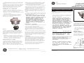
Attach the trunnion to each side of the fixture housing
using the hardware provided. See Figure A. It is not
necessary to fully tighten the screws until after the unit has
been mounted and aimed.
Figure A
Installez solidement le tourillon sur une surface d’appui
convenable, avec les deux trous de 0,562 po ou le trou de
0,875 po.
Alors que les deux vis retenant le tourillon au ballast sont
desserrées, orientez le projecteur dans la direction désirée.
Un indicateur de degrés est fourni sur le tourillon pour
faciliter l’alignement du faisceau lumineux. Après
l’orientation, serrez solidement les deux vis.
ASSEMBLAGE DU CONNECTEUR
Enlevez le sectionneur électrique sur le connecteur.
Installez un conduit ou un câble acceptable sur le boîtier du
connecteur en utilisant les filets d’entrée fournis.
Remarque : Au moins cinq filets doivent être vissés.
Serrez la vis d’arrêt.
Connectez les fils d’alimentation sur le sectionneur
électrique conformément aux étiquette de codes de
couleurs, s’il y a lieu. Réinstallez le sectionneur sur le
connecteur (voir la figure B).
Figure B
Vissez le connecteur dans le boîtier du ballast. Le
sectionneur électrique s’accouplera automatiquement
lorsque cinq filets auront été vissés. Continuez à visser
jusqu’à ce que le connecteur soit solidement vissé dans le
boîtier du ballast, puis serrez la vis d’arrêt en bas du
connecteur.
REMARQUE : Les filets du boîtier du ballast qui
servent à l’assemblage ci-dessus ont été lubrifiés en
usine avec du Versalube General Electric G322L. Si
nécessaire, une quantité supplémentaire de
lubrifiant du même type peut être appliquée.
INSTALLATION DE LA LAMPE
Avant de remplacer la lampe, déconnectez le circuit
d’alimentation électrique. Desserrez la vis d’arrêt près du
rebord inférieur du boîtier du ballast. Dévissez l’anneau
d’appui du globe en verre, lequel est installé sur le
boîtier du ballast. Pour faciliter l’enlèvement de cet
anneau, un tournevis peut être inséré dans les fentes de
soulèvement. Vous pouvez également desserrer l’anneau
en tapant légèrement sur les cannelures de l’anneau.
Sur la plaque signalétique, vérifiez les spécifications
concernant le type de la lampe et sa puissance.
Vous risquez d’endommager le projecteur si la lampe est
insérée alors qu’il est sous tension ou si la lampe est mal
serrée dans la douille lorsque la tension électrique est mise.
SERRAGE DE LA LAMPE : La lampe doit être
solidement insérée avec une force de 35 lb/po (normes
NEMA-EEI), ce qui peut être obtenu avec un serrage très
ferme. Le serrage doit être suffisant pour enfoncer
complètement la lampe et charger le contact central de la
douille.
Lorsque la lampe est installée, revissez l’anneau du globe
sur le boîtier du ballast, jusqu’à ce qu’il soit solidement fixé.
Serrez ensuite la vis d’arrêt.
AVERTISSEMENT : NE TENEZ PAS LE GLOBE EN
VERRE POUR DESSERRER L’ANNEAU CAR VOUS
RISQUERIEZ ALORS DE DESSERRER LA BAGUE DE
SERRAGE DU VERRE. SI CETTE BAGUE EST
ACCIDENTELLEMENT DESSERRÉE, ELLE DOIT
ÊTRE ENTIÈREMENT RESSERRÉE AVANT
D’UTILISER LE LUMINAIRE. POUR RESSERRER,
DESSERREZ LA VIS D’ARRÊT SUR LA BAGUE DE
SERRAGE ET SERREZ LA BAGUE AVEC UN
COUPLE DE 40-45 LB-PI, PUIS RESSERREZ LA VIS
D’ARRÊT.
RÉFLECTEURS EXTÉRIEURS
S’il y a lieu, un réflecteur est fixé à la base de l’anneau du
globe, avec les trois vis fournies à cet effet.
Si un protège-globe a été installé sur le luminaire, le
réflecteur est fixé avec les mêmes vis qui tiennent le
dispositif de protection. Ces vis doivent simplement être
desserrées, puisque le réflecteur possède des fentes en
serrure.
Si un réflecteur angulaire est utilisé, orientez le réflecteur
avec les trois vis, de façon à ce que le faisceau principal de la
lampe soit près de la direction désirée. Lorsque la vis d’arrêt
à été desserrée, l’anneau du globe peut être légèrement
tourné pour terminer l’orientation du réflecteur. Resserrez
ensuite la vis d’arrêt.
ENTRETIEN
Il sera occasionnellement nécessaire de nettoyer le
module optique pour conserver un éclairage puissant. La
fréquence des nettoyages dépendra du niveau de saletés
dans l’environnement d’utilisation et de la puissance
d’éclairage minimale requise. Le réflecteur peut être
nettoyé avec n’importe quelle solution non abrasive à base
d’eau mélangée avec du savon ou un détergent doux.
Rincez ensuite à l’eau claire pour enlever les résidus de
solution nettoyante. Le verre peut être nettoyé avec
n’importe quel liquide lave-vitre courant.
These instructions do not purport to cover all details or variations in equipment nor to provide for every possible contingency to be met in connection with installation, operation or
maintenance. Should further information be desired or should particular problems arise which are not covered sufficiently for the purchaser’s purposes, the matter should be referred
to GE Lighting Solutions.
g
GE Lighting Solutions is a subsidiary of the General Electric Company. Evolve and other trademarks belong to GE Lighting Solutions. The GE brand and logo are trademarks of the General Electric Company.
© 2011 GE Lighting Solutions. Information provided is subject to change without notice. All values are design or typical values when measured under laboratory conditions.
GE Lighting Solutions • 1-888-MY-GE-LED • www.gelightingsolutions.com
16943533----888
g
GE
Lighting Solutions

Mount the trunnion securely to a suitable supporting
surface using the two .562 holes or the .875 hole provided.
With the two screws holding the trunnion to the ballast
housing loosened, aim the fixture in the desired direction.
A degree indicator is provided on the trunnion to aid in
alignment of the fixtures. Tighten the two screws securely
after aiming.
CONNECTOR ASSEMBLY
Remove the electrical disconnect from the connector
assembly. Attach a suitable cable assembly or conduit to the
connector housing using the entrance threads provided.
Note: Five threads minimum must be engaged.
Tighten the set screw.
Connect the supply wires to the electrical disconnect
according to the color coding labels if applicable. Refasten
the disconnect into the connector assembly. See Figure B.
threads into the ballast housing. To assist in removing
this globe ring, a screw driver can be inserted in the pry
slots, or the globe ring can be loosened by lightly
tapping on the globe ring ribs.
Lamp type and wattage should be checked against
the ballast assembly nameplate.
Damage may occur to the fixture if the lamp is inserted
while power is on, or if the lamp is not tight in the socket
when power is applied.
LAMP TIGHTNESS: The lamp should be securely
inserted to the NEMA-EEI specified torque of 35 inch-
pounds, which is best achieved by very firmly tightening to
insure application of sufficient torque. Tightening must be
sufficient to fully depress and load the center contact of the
socket.
After lamp is installed, rethread globe ring into ballast
housing until it firmly seats. Tighten set screw.
WARNING: DO NOT HOLD GLASS GLOBE TO
UNTHREAD GLOBE RING AS THIS MIGHT LOOSEN
GLASS CLAMP RING. IF GLASS CLAMP RING IS
ACCIDENTALLY LOOSENED, IT MUST BE FULLY
RETIGHTENED BEFORE LUMINAIRE IS USED. TO
RETIGHTEN: LOOSEN THE SET SCREW ON THE
CLAMP RING AND TIGHTEN THE CLAMP RING TO
40-45 FOOT-POUNDS. RETIGHTEN THE SET
SCREW.
EXTERNAL REFLECTORS
A reflector, if used, is attached to the bottom of the globe
ring with the three screws provided.
If a globe guard is on the unit, the reflector is attached
using the same screws that hold the guard. These screws
need only be loosened since the reflector is provided with
keyhole slots.
If an angle reflector is used, orient the reflector with
respect to the three screws so that the main light output is
near the desired direction. After loosening the set screw the
globe ring can then be slightly rotated to complete the
reflector orientation. Then retighten the set screw.
MAINTENANCE
It will occasionally be necessary to clean the optical
assembly in order to maintain the light level. Frequency of
cleaning will depend on the dirt level in the user’s facility
and the minimum light level which is acceptable to him.
The reflector should be cleaned with any suitable
non-abrasive solution of water and soap or detergent.
Residual cleanser should be removed by clean water
rinsing. The glassware may be cleaned with any
conventional glass cleanser.
Thread the connector assembly into the ballast hous-
ing. The electrical disconnect will automatically mate after
five threads have engaged. Continue engaging until the
connector assembly is tightly threaded into the ballast
housing and then tighten the set screw at the bottom of the
connector assembly.
NOTE: Threads on the ballast housing to accept the
above mountings are factory lubricated with
General Electric Versalube G322L. Additional
lubricant of the same type may be applied if
necessary.
LAMP INSTALLATION
Disconnect the power supply circuit before relamping.
Loosen the set screw near the bottom edge of the ballast
housing. Unthread the glass globe support ring which
Figure B
GEH-5921
INSTRUCTIONS
FLOODLIGHT POWR•GARD
™
Installation et entretien
LUMINAIRE POUR SITES DANGEREUX
LIRE ATTENTIVEMENT AVANT D'INSTALLER
GÉNÉRALITÉS
Ce luminaire est conçu pour les environnements dangereux.
Toutes les connexions doivent être conformes aux
normes électriques nationales et à la
réglementation locale en vigueur.
AVERTISSEMENT : DES TENSIONS DANGEREUSES
SONT PRÉSENTES DANS CES LUMINAIRES ET
TOUTES LES PRÉCAUTIONS NORMALEMENT EN
VIGUEUR LORS DES MANIPULATIONS
D’ÉQUIPEMENTS HAUTE TENSION DOIVENT ÊTRE
PRISES LORS DU REMPLACEMENT DE LA LAMPE,
AINSI QUE DE TOUTE RÉPARATION DU LUMINAIRE.
L’IGNORANCE DE CET AVERTISSEMENT PEUT
PROVOQUER UNE ÉLECTROCUTION, AINSI QUE
D’AUTRES BLESSURES AUX PERSONNES QUI
INSTALLENT OU RÉPARENT L’ÉQUIPEMENT.
LA TEMPÉRATURE DE FONCTIONNEMENT
“ T-CODE “ FIGURANT SUR CE LUMINAIRE EST
BASÉE SUR L’UTILISATION D’AMPOULES DES
GROSSEURS CI-DESSOUS.
L’UTILISATION D’UNE AUTRE AMPOULE RISQUE DE
PRODUIRE DES TEMPÉRATURES DE
FONCTIONNEMENT PLUS ÉLEVÉES ET
DANGEREUSES.
TYPE D’AMPOULE PUISSANCE GROSSEUR
(W) DE L’AMPOULE
SODIUM HAUTE PRESSION 70,100,150 ED 23 1/2
SODIUM HAUTE PRESSION 250, 400 ED 18
HALOGÉNURES/MERCURE 175, 250 ED 28
HALOGÉNURES/MERCURE 400 ED 37
Figure A
MISE EN GARDE : Avant d’installer ce luminaire,
vérifiez les limites de température de
fonctionnement sur le ballast pour vous assurer
qu’elles respectent les restrictions
environnementales de température et les normes
du code électrique national.
AVERTISSEMENT : POUR ÉVITER UNE
DÉFLAGRATION DANS UNE ATMOSPHÈRE
DANGEREUSE, DÉCONNECTEZ LE CIRCUIT
D’ALIMENTATION DU LUMINAIRE AVANT DE
CHANGER LA LAMPE, D’ENLEVER LE LUMINAIRE
OU D’EFFECTUER TOUTE AUTRE TÂCHE
D’ENTRETIEN
DÉBALLAGE
Le ballast et les raccords d’assemblage ont été
soigneusement emballés dans des caisses séparées pour
qu’aucune pièce ne subisse de dommages durant le trans-
port. Enlevez les matériaux d’emballage utilisés pour
protéger les filets et procédez à une inspection. Ne tentez
pas d’assembler ou d’utiliser des pièces ayant des filets
endommagés.
Vérifiez si la tension d’alimentation est conforme aux
exigences de la plaque signalétique. Vérifiez également sur
la plaque signalétique les spécifications des lampes pouvant
être utilisées avec le ballast.
INSTALLATION
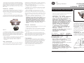
ASSEMBLAGE DU LUMINAIRE
Avec la visserie fournie, fixez le tourillon sur chaque côté
du boîtier du luminaire (voir la figure A). Il n’est pas
nécessaire de complètement serrer les vis tant que le
projecteur n’a pas été complètement installé et orienté.
TOURILLON
RONDELLE DE FREIN
BOULON .50-13
BOITIER
RONDELLE DE FREIN
Ces instructions n'ont pas pour destination de couvrir tous les détails ou variantes de l'équipement, ni de répondre à toutes les éventualités que vous pourriez rencontrer pendant l'installation,
le fonctionnement ou l'entretien. Si vous souhaitez des informations complémentaires, ou si vous rencontrez un problème particulier qui ne soit pas adressé de votre point de vue d'acheteur,
le sujet doit être remonté jusqu'à la société GE Lighting Solutions
g
GE
Lighting Solutions
-
 1
1
-
 2
2


dans d''autres langues
- English: GE H9 Luminaire Installation guide
Documents connexes
-
GE H9 Luminaire Guide d'installation
-
GE MGA Guide d'installation
-
-
-
-
-
-
-
GE GFPS & GFPT Guide d'installation
-