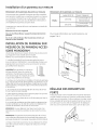
GE ZBD9900R00II Guide d'installation
- Catégorie
- Lave-vaisselle
- Taper
- Guide d'installation

Installation Instructions
Built-In Dishwasher
Ifyou have questions, call 800.GE.CARES1800.432.2737)or visit our Website at: GEAppliances.com.
In Canada, please call 1.800.561.3344or visit www.geappliances.ca
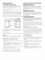
BEFOREYOU BEGIN
Readthese instructions completely and
carefully.
M PORTANT - Observeallgoverningcodesand
ordinances.
. Note to Installer - Be sure to leave these instructions for the
consumer's and local inspector's use.
. Note to Consumer - Keep these instructions with your
Owner's Manual for future reference.
. Skill Level - Installation of this dishwasher requires
basic mechanical, electrical and plumbing skills. Proper
installation is the responsibility of the installer. Product
failure due to improper installation is not covered under
the GEAppliance Warranty. Seewarranty information.
. Completion Time - 1 to 2;Hours. New installations require
more time than replacement installations.
IM PORTANT - The dishwasherMUST be installed
to allow for future removal from the enclosure if service is
required.
If you received a damaged dishwasher, you should
immediately contact your dealer or builder.
Optional Accessories - Seethe Owner's Manual for available
custom panel kits.
FOR YOUR SAFETY
Read and observe all CAUTIONSand WARNINGSshown
throughout these instructions. While performing
installations described in this booklet, gloves, safety glasses
or goggles should be worn.
READ CAREFULLY.
KEEP THESE INSTRUCTIONS.
31-30264 09/23/10 GE

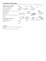
Installation Preparation
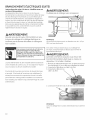
TOOLS YOU WILL NEED:
CI Phillips No. 2 screwdriver
CI Flat blade screwdriver
CI Torx screwdriver sizeT 20 Ph
screwdriver
CI Adjustable wrench
CI Open-ended wrench (1/2" [!2 mm] or 5/8" [!6 mm])
CI Measuring tape
CI Safety glasses
CI Flashlight
CI Bucket to catch water when flushing the line Open-ended wrench
CI Gloves
CI Level
For New Installations Only:
cI Tubing cutter
CI Drill and appropriate bits
CI Hole saw set
Flashlight
%
Gloves
_ --__ Level
Flat blade _ Tar× screw-_%
screwdriver driver size T 20
Adjustable
Wrench _
Safety Glasses
Hole Saw Set
Bucket
Measuring Tape
MATERIALS
CI Minimum 3/8" ODcopper tubing of sufficient length for your
installation
CI Shut-off valve and fittings for water supply line

Installation Preparation
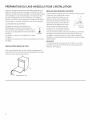
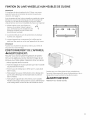
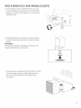
DISHWASHER CAVITY MEASUREMENTS
® O
90°
2 _/.j/,
50-i05mm
Cable Hole
1-1/2" Max DIA.
QQmm DIA.
W : 610 mm
* Actual width of Dishwasher allows for
installation in a 23-5/8" wide cutout.
If optional Stainless Steel door panel
(ZXSS9900)is used,the cutout MUSTbe
24".
Make sure the edges of the cable
hole are even to avoid damage to
the drain and supply hoses and the
electric cable.
NOTE: A 24" cutout may require additional
trim work for the inside of the cutout for a
finished appearance.
Dishwasher door shown
without custom panel or
panel kit
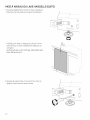
I
34-1/4to36-1/8"
_ 870-920mm
iO
** 28-3/8" to 3!-!/2"
72!-800mm
J
3/4" thick
19 mm
CUSTOM PANEL
** Height must be 28-3/8" iVllN.- 31-1/2"
MAX.to accommodate different toe kick
heights.
*** Custom panel must have 1/8" min.
clearance on each side for proper fit in
cabinet cutout.

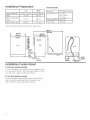
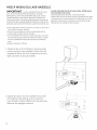
Installation Preparation Technical Data
U.S. Metric
Height (Adjustable) 33-3/4" - 35-3/4" 857 to 908 mm
Width 23-3/8" 600 mm
Depth (Includes high 22-7/8"* 581 mm
loop)
Depth W/Door Open 49-3/4" 1266 mm
*Does not include the depth of a custom or optional door.
Electricity 120V,60Hz, 15 amp
Water pressure: 4.2-140 psi,
0.03-!.0 HPa,
0.3-10 Bar
Heating element: 1200 watt
Max loading 1300 watt
23-3/8" ),_
600 mrn
_=,,=,=,=,=,=,=_
=-
o
Front
|
m
E
E
¢o
o
o_
o
Lo
¢o
E
49-3/4"
1266 rnrn
22=7/8"
581 rnrn
[12"
50 mm
'-'b
85 mm _ 238 mm _
2=3/4"
70 rnrn
Installation Custom Panel
4" TOE KICK INSTALLATIONS
4" toe kick installations are possible using the supplied toe kick
or a custom built toe kick. Custom door panel height can be up
to 31-1/2" max. to align with adjacent cabinets.
6" TOE KICK INSTALLATIONS
6" toe kick installations are possible using a custom toe kick
only. Custom door panel height can be reduced to a min.
height of 28-3/8" to align with adjacent cabinets.

Installation Custom Panel
Custom Door Panel Dimensions
Your new Monogram dishwasher can be installed with a fully
integrated, buyer supplied custom door panel or Hongram
accessory panel that extends from the toe kick to the counter
top. The unit comes with everything needed to make installing
the door panel easy.
The custom panel should be a minimum of 3/4" (!9mm) thick.
Items provided with the unit
Two 3/8" screws (B)for temporarily hanging the panel.
Six 1-3/4" screws (D)for mounting the custom wooden panel
to the dishwasher.
Custom Panel Dimensions
Up to 15 Ibs, with unit
wtnt'"eg": 15-19 Ibs. Order 1X
WD01X10445
19-23 Ibs. Order 2X
WD01X10445
For dimensional information see pages 3 and 4.
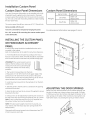
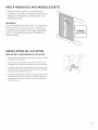
INSTALLING THE CUSTOM PANEL
OR MONOGRAM ACCESSORY
PANEL
A custom door panel should be installed before the unit is
mounted to the cabinet.
Refer to the illustration at the right for instruction references.
1. Fit the handle (A)onto the panel according to the manu-
facturer's instructions. (NOTE:A handle should be used rather
than a knob, because a knob does not provide enough grip.)
IMPORTANT!The custom panel must not IJ
obstruct the fan exhaust vent; otherwise,
L
moisture from the vent could eventually
damage the cabinet and create drying
problems. Ea
2.The two short screws (B)go into the back
of the panel 15-7/16" (392 mm) from the upper edge of the
panel and 10-7/8" (266 mm) from the center of the panel.
Insert the short screws into the panel, leaving 1/8" (3 mm) of
space between the screw head and the panel.
3. Hook the panel screws (B)into the keyholes (C)on the dish-
washer door.
4. Slidethe panel to the left until it is centered in the opening
and secure the screws.
5. Open the door and use the six screws (D)supplied to secure
the panel to the door.
6. Exhaust vent can be adjusted by loosening vent screws on
the side of the door and moving the exhaust vent up or down.
Note: If vent is pulled downward too far it will seperate from
the exhaust conduit and must be reattached.
NOTE:If the door panel weighs more than !5 pounds, you
may need to order the heavy-duty door springs (Order Kit #
WD01X10445).
Max panel width cannot exceed cutout dimensions less 1/8"
(2.Smm)reveal on each side.
B
ADJUSTING THE DOOR SPRINGS
Before you push the dishwasher into the cabinet opening, test
the door to make sure it stays in place at any angle. If it tends
to fall down, pull out the machine and adjust the tension of the
door springs on the sides of the machine by moving them one
hole farther back or by twisting the spring to make it shorter.
en

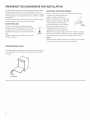
PREPARING THE DISHWASHER FOR INSTALLATION
At this point the styrofoam, plastic wrap, and the wood pallet
(base)should be removed from the dishwasher. Now isan
excellent time to inspect for any shipping damage. Should you
find any damage, you should report it to your dealer or builder
immediately.
Be sure to remove the toe kick and toe kick insulation (only on
certain models) from the top of the dishwasher.
SLIDES FOR LEGS
The unit comes with white plastic slides for ........
the legs to protect the kitchen floor from being ........ _._
damaged when you slide the unit into place. _The slides simply snap onto the bottom of the
legs.
Protective slides for legs simply snap onto the
bottom of the legs.
ADJUSTING THE DOOR SPRINGS
Before you install the unit into the cabinet, open the door
to make sure it stays open at any .-
angle. If it tends to full down or
snap shut, pull out the machine and
tension the door springs on the sides
of the machine by moving them
one hole further back or by twisting
the spring to make it shorter. The
accessory door panel or custom
wood panel must be installed on FI
dishwashers to properly adjust tension on the door springs. If
that doesn't resolve the problem, you may need to purchase
the heavy-duty door springs (part number WD01X10/4/45).
NOTE:
If the door pond weighs more than !5 pounds, you may need
to order the heavy-duty door springs. (Seepage 5.)
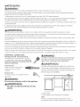
CORNER INSTALLATION
If the dishwasher is installed in a corner, there must be o mini-
mum clearance of 2" (50 mm) from the side wall so the door
can open.
2" clearance

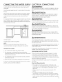
WATER SUPPLY
A WARNING:
Plumbing connections must comply with applicable sanitary, safety and plumbing codes in your area.
The machine can be connected to either a hot or cold water supply. If a cold water supply is used, the washing times will be
longer but the performance will not be affected.
The dishwasher comes with a 6-foot PEXwater supply line that has a 3/8" NPTfemale connection.
After determining where the water supply line will enter under the sink, drill a 1-1/2" access hole and run the line to the approxi-
mate inlet valve location shown in the fgure below. Thewater line inlet valve ison the right rear of the machine.
For service convenience, a shut-off valve (not supplied) should be installed in the supply line in an easily accessible location, such
as, beneath the sink.
It is important that the water supply line and the shut-off valve have a sumcient flow volume. At last 3 gallons (12 liters) per
minute must be able to pass through the line.The water pressure should be 4.2-140 psi.
ADVERTENCIA:
Las conexiones de plomer[a deben cumplir con los cbdigos sanitarios, de seguridad y de plomer[a vigentes en su _rea.
La m_quina puede conectarse al suministro de agua caliente o de agua frfa. Sise utiliza el suministro de agua if[a, los tlempos
de lavado ser_n m_s prolongados pero el desempe_o no sever_ afectado.
El lavavajillas viene con una I[nea de suministro de agua de polietileno reticulado de 6 pies que cuenta con una conexibn hem-
bra NPTde 3/8".
Despu_s de establecer el lugar en donde secolocar_ laI[nea de suministro de agua debajo del fregadero, perfore un orificio de
acceso de !-!/2" y distribuya la I[nea hasta la ubicacibn aproximada de la v_lvula de ingreso indicada en la imagen de abajo. La
vdlvula de ingreso de la I[nea de agua se encuentra en la parte trasera derecha de la m_quina.
Para mayor comodidad cuando se realiza una reparacibn, debe instalarse una v_lvula de cierre (no provista) en la I[nea de sum-
inistro en una ubicacibn f_cilmente accesible, coma par ejemplo, debajo del fregadero.
Resulta importante que la I[nea de suministro de agua y la v_lvula de cierre tengan un volumen de flujo suficiente. Par Io menos
3 galones (12 litros) par minuto deben poder pasar a travbs de la I[nea. La presibn del agua debe set de 4.2-!40 psi.
EASYINSTALL CONNECTIONS
PEXtubing with 3/8" compression fitting
PEXtubing has u 95-year spec life. FitsAmeri-
can dishwasher water supply valves. Be sure to
install the O-Ring which is attached to the PE×
tubing in a plastic bag.
Drain hose boot
Ready to be cut to desired drain
connection. Only one clamp
required.
Electrical cord
!20 volts, !5 amp cord is supplied with the
dishwasher.
A WARNING:
Do not use an extension cord for this appliance.
ADVERTENCIA:
No utilice un cable de extensi6n con este
aparato.
WARNING:
In order to prevent heat damage to the inlet valve,
all solder connections must be m(]de before the
water line is connected to the dishwasher.
DVERTENCIA:
A fin de evitGr dGSos provocGdos par el cGIor e la
vblvulo de entradG, deben reGlizGrse todGs las con-
exiones mediGnte soldGdurG antes de conectGr IG
Ifnee de aguG al IGvavajillGs.
#r -1_ _-=_---='-==,_l _:'=====-=
t_
E_
(1)',:
Eg
Ig
I
(2) ,,
_ J
IF
h
1. Water supply
2. Water supply valve to dishwasher (not supplied)
NOTE:
Be sure to run the PEX tubing through the hole to sink
compartment before moving the dishwasher into position.

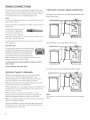
DRAIN CONNECTIONS
GEprovides a 7/8" (22 mm) diameter corrugated drain hose
which isconnected to the back of the unit to form a high loop.
If additional drain hose is needed, please purchase a drain
hose extension kit with a 7/8" (22mm) copper tube.
NOTE:
Do not use any fittings anywhere in the drainline that are less
than 7/8" (22mm) ID.
The access hole for the drain line should be 1-5/8" (41 mm)- 2"
(50mm) max.
The end of the drain line is 1/2"
(12 mm), but it is adjustable
to 7/8%3/4%5/8" (22mm, 19
mm, and 16 mm). If the drain
connection islarger than 1/2" (12 mm), you can easily cut the
drain line to fit the connection.
The illustrations to the right show three ways to connect the
drain supply line.
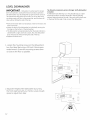
THE HiGH LOOP
The high loop is necessary for proper draining.
Therefore, the dishwasher has the drain hose
attached to the drain pump and fastened to
the top back of the unit, as illustrated. This
gives the drain hose an automatic high loop,
which isnecessary for proper draining. The drain hose is
fastened at the best high loop height.
To eliminate potential drain problems, simply leave this
hose in place.
DO NOT REMOVE THE HIGH LOOP!
IMPORTANT THINGS TO REMEMBER:
I_ Failure to provide the proper drain connection height
(minimum of 20" (508 mm) above the bottom of the
dishwasher base) or a 20" (508 mm) high loop will result in
improper drainage, which will damage the machine.
I_ No part of the drain hose should be higher than 35" (889
mm) from the bottom of the dishwasher.
I_ The drain hose can be extended to a maximum length of 10
feet (3048 mm).Joints and jointed tubes, if any, must have a
minimum 5/8" (16 mm)ID.
I_ If the drain line is going to be connected to a waste
disposer, be sure to remove the knockout or plug from the
fitting on the disposer before connecting the drain line.
I_Do not usefittings smaller than 5/8" (16 mm); otherwise the
water may not drain properly.
When the installation is ready, open the supply valve and let
the pressure act for a while. Then check that all connections
are tight and there are no leaks.
THREE WAYS TO INSTALL DRAIN CONNECTIONS
A) Typical connection to sink plumbing before trap
(high loop drain).
,,'[11
B) Connection to air gap then to the trap.
C)Connection to waste disposer with air gap.
i'_Ji
.:,.- = --
/
NOTE:
Don't forget to remove the knockout or plug from the disposer
fitting.

CONNECTING THE WATER SUPPLY
In order to prevent heat damage to the inlet valve, all solder
connections must be made before the water supply line is
connected.
Flush the water supply line prior to connecting it to the water
fill tube.
The unit has a float switch in the base pan to protect against
flooding. If the inlet valve connection is not seated properly,
water may leak into the base pan and activate the float
switch.
It is important that the water supply line and the shut-off valve
have a sumcient flow volume. At last 3 gallons (12 liters) per
minute must be able to pass through the line.The water pres-
sure should be 4.2-140 psi.
rl
t_
(1)I',
ii
h
(1)Water supply
(2)Water supply valve (not supplied)
NOTE'.
Be sure to run the PEXtubing through the hole to sink
compartment before moving the dishwasher into position.
TESTING FOR LEAKS
1.Turn on the water supply and check for leaks.
2.Turn the power on at breaker/fuse box and test the
dishwasher operation by running a Rinsecycle. (Thisshould
take about four minutes.)
3.Turn off the electrical power and check for leaks under the
dishwasher and sink.
4. Make sure that no kinks have developed in the drain lines.
If there are no leaks and the dishwasher seems to be working
properly, continue with the installation.
ELECTRICAL CONNECTIONS
WARNING:
Before working on wiring for any electrical appliance, be sure
the electrical power has been turned off at the breaker/fuse
box.
, ADVERTENCIA:
Antes de comenzar a trabajar con el cableado de cualquier
aparato el6ctrico, asegOrese de haber desconectado la en-
erg[a desde el interruptor/caja de fusibles.
WARNING:
Disconnect electrical power supply and place a tag at the dis-
connect switch indicating that you are working on the circuit.
,tkADVERTENCIA:
Desconecte el suministro de energ[a el6ctrica y coloque una
etiqueta en el interruptor de desconexi6n indicando que usted
se encuentra trabajando en el circuito.
WARNING:
Electrical and grounding connections must comply with the
applicable portions of the national electrical code and/or other
local electrical codes.
, ADVERTENCIA:
Las conexiones el6ctricas y a tierra deben cumplir con las
partes aplicables del c6digo el6ctrico nacional y/u otros c6di-
gas el6ctricos locales.
The dishwasher comes with an electrical cord for 120 volts, 15
amp supplied. This cord should be plugged into the 120 volt
outlet under the sink.
If the cord is not long enough, or if a hard-wire installation is
needed, follow instructions on page 10).
GROUNDING INSTRUCTIONS
This unit must be grounded to operate properly. It must be
connected to a grounded metal, permanent wiring system,
or an equipment-grounding conductor must be run with the
circuit conductors and connected to the equipment-grounding
terminal or lead of the appliance.
Damage to the dishwasher could occur if it is not properly
grounded.
Electrical Requirements
. This appliance must be supplied with Z20V,60Hz.,and
connected to an individual properly grounded branch circuit
protected by a 15- or 20-ampere circuit breaker or time-
delay fuse.
. Wiring must be 2 wire with ground and rated for 75°C
(176°F).
. If the electrical supply does not meet the above
requirements, call a licensed electrician before proceeding.
. Do not modify the plug provided with this appliance, if it will
not fit the outlet, have a proper outlet installed by a qualified
electrician. 9

ELECTRICAL CONNECTIONS (CANT)
Grounding Instructions-Power Cord Models
This appliance must be grounded. In the event of a
malfunction or breakdown, grounding will reduce
the risk of electric shock by providing a path of
least resistance for electric current. This appliance
is equipped with a cord having an equipment-
grounding conductor and a grounding plug. The
plug must be plugged into an appropriate outlet
that is installed and grounded in accordance with all
local codes and ordinances.
,& WARNING:
Make sure the water supply line, drain line and
branch circuit wiring do not touch any exposed ter-
minals of dishwasher wiring.
AADVERTENCIA:
Verifique que la linea de suministro de agua, linea
de drenuje y cableudo del circuito derivudo no
toquen ningunu terminal expuestu del cubleudo del
luvuvujillus.
The improper connection of the equipment
grounding conductor can result in a risk
of electric shock. Check with a qualified
electrician or service representative if you
are in doubt that the appliance is properly
grounded.
La conexi6n incorrecta del conductor de
conexi6n a tierra del equipo puede resultar
en choque ei_ctrico. Consulte con un
electricista calificado o representante
de servicio si tiene dudas de la conexi6n
a tierra del aparato.
The power-supply receptacle for the dishwasher is
to be installed in a cabinet or on a wall adjacent to
the undercounter space in which the dishwasher is
to be install.
,& WARNING:
Do not use an extension cord for this appliance.
ADVERTENCIA:
No utilice un cable de extensi6n con este aparato.
a_
/I..
- i
NOTE:
Access holes should be !-!/2" max (38.! mm max) in diameter
wlfl_ no sT_arpe_Iges.
If the cord is not long enough, or if a hard-wire installation
is needed, follow the steps below to complete the electrical
connection.
WARNING:
Before starting this procedure, be sure the power is
turned off at the breaker/fuse box.
1. Connect supply cable with a UL-listed strain relief bushing (if
nonmetallic cable isto be used).
2. Connect branch circuit white
lead to N lead on filter.
3. Connect branch circuit
black
lead to L lead on filter.
/4.Connect ground wire
to ground connection
screw on the bottom.
If the edges of the opening is wood it must be
smooth and rounded. If the edges of the opening
is metal it must be covered by an edge protector
provided for this purpose by the manufacturer. Be
careful when installing or removing the dishwasher,
to reduce the likelihood of damage to the power-
supply cord.
10
AADVERTENCIA:
Antes de comenzar este procedimiento, aseg0rese de haber
apagado la energ[a el6ctrica desde el interruptor/caja de
fusibles.
1. Conecte el cable de suministro con un casquillo de alivio de
tensi6n aprobado par UL(sino seva a utilizar un cable no
met61ico).
2. Conecte el cable blanco de circuito derivado al cable Ndel
filtro.
3. Conecte el cable negro de circuito derivado al cable L del
filtro.
/4.Conecte el cable a tierra al tornillo de conexi6n a tierra en la
parte inferior.
NOTE:
When doing a hard-wire installation, you must remove the
supplied power cord.

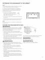
FASTENING THE DISHWASHER TO THE CABINET
NOTE:
If the door panel weighs more than !5 pounds, you may need
to order the heavy-duty door springs. (Seepage 5.)
It's necessary to fasten the dishwasher to the cabinet so
it won't tilt when the door isopened or if something heavy
is placed on the door. Use only the stainless steel screws
provided with the machine.
1. Use option A for mounting to underside
of counter-top. Useoption Bfor mount-
ing to cabinet side when counter-top isa
hard surface such as granite.
2. Cover the screw heads with the plastic plugs provided with
the machine.
3.When the machine is properly attached, check that the feet
are tight against the floor and that the machine islevel.
NOTE:
Be sure to use white spacers to keep from over-tightening the
mounting screws.
B
lit "1
MOVING THE MACHINE INTO PLACE
,tkWARNING:
Hake sure you put the protective slides on the legs
to prevent damaging the floor when you slide the
unit into place (see page 9).
1. Position the machine in front of the cabinet opening.
2. Hake the height adjustment while the dishwasher is in front
of the opening.
3. Pull out the drain hose to ensure there are no sharp bends.
4. Start to feed water and drain lines and electric cord (if nec-
essary) into the access hole in the cabinet.
5. Gently slide the unit into the dishwasher opening. As you do
this, feed the drain line and inlet hose into the access hole
in the side of the cabinet.
,tkADVERTENCIA:
Aseg0rese de colocar los deslizadores protectores en las
patas para evitar duflos ul piso cuundo deslice lu unidud en
su lugar (ver p6gina 9).
1. Coloque la m6quina frente u lu aberturu del gabinete.
2. Realice el ujuste de altura mientrus el luvuvajillus se en-
cuentra frente a la ubertura.
3.Tire de la manguera de drenaje para verificur que no haya
torceduras.
/4.Comience a colocar las lineas de agua y de drenaje y el
cable el6ctrico (sifuera necesario) dentro del orificio de ac-
ceso del gabinete.
5. Suavemente deslice la unidad dentro de la abertura del
lavavajillas. Hientras Io hace, coloque la linea de drenaje y
la manguera de entrada dentro del orificio de acceso en el
lado del gabinete.
Asyou slide the unit into place, feed the drain line and inlet
hose into the access hole in the side of the cabinet.
WARNING:
Be careful of sharp edges.
DVERTENCIA:
Tenga cuidado con los bordes afitados.
11

LEVEL DISHWASHER
IMPORTANT Dishwasher must be levelfor proper
dish rack operation, wash performance and door operation.
The dishwasher must be leveled left to right and front to back.
This assures the dish racks will not roll in or out on their own,
circulation water will flow to the pump inlet, and the door will
close without hitting the side of the tub.
. Remove the lower dish rack and place a level on the door and
lower rack track.
. Adjust the level of the dishwasher by individually turning the
four legs on the bottom of the dishwasher.
. The dishwasher isproperly leveled when the level indicator is
centered left to right and front to back. Also, the dishwasher
door should close without hitting the side of the tub.
. Replace the lower rack.
Tip: Prevent unnecessary service charges. Verify dishwasher
is leveled.
Pull the dish racks half way out. They should stay put. Open
and close the door. Thedoor should fit in the tub opening
without hitting the side of the tub. If the racks roll on their own,
or the door hits the side of tub, re-level the dishwasher.
1. Loosen the mounting screws on the dishwasher's
two front steel feet using a 5/8 inch (16mm) open-
ended wrench. Screw the mounting screws down
as close to the floor as possible.
2. Adjust the height of the dishwasher by turning
the front steel feet with your hands. Leave enough
space to adjust them later.
rx
.................... i f .....................
kJ'
......... /:
©
12

LEVEL DISHWASHER (CONT}
3. Screw in the back foot completely by turning the
adjustment screw at the front counterclockwise.
Use a flat-bladed or a 1/4 inch nut driver.
4. Push the plastic feet into place on all three steel
feet (included in document bag).
NOTE:
Do not attach the plastic feet if the installation space
is of minimum height.
5. Push the dishwasher into the cavity. At the same
time, pull the electric cable and drainage and supply
hoses through the cable hole.
13

LEVEL DISHWASHER ICONT}
6. Lift the dishwasher (] little at the front and turn
the front feet to lower them.
7. Check that there is o 1/8 inch (3mm) space be-
tween the top of the dishwasher door and the
underside of the counter.
Do not ottoch the mounting screws. This will be
done later.
1/8"
3mm
i
i
i
i
i
8. Adjust the back foot by turning the adjustment
screw at the front clockwise.
14

LEVEL DISHWASHER (CONT)
9. Place the spirit level on the dishwasher door to
check that the machine is level and adjust if nec-
essary. The door must be fully closed!
NOTE:
The dishwasher must be level!
An unlevel machine can affect the amount of water
taken in, the door can be difficult to close, and the
baskets difficult to place securely.
I I
INSTALLING THE TOE KICK
SETTING THE TOE KICK DEPTH
1. Pressthe grey catches towards each other to release the
toe kick brackets.
2. Pull out the toe kick brackets as far as the installation re-
quires to provide the proper toe kick depth.
3. Once the toe kick brackets are at the appropriate depth,
press the grey catches away from each other to lock the
toe kick brackets in place.
4.The back side of the toe kick has hooks that will hang the
toe kick on the toe kick brackets. Lift the toe kick up and let
the hooks slide onto the brackets as you lower the toe kick
to the floor.
15

INSTALLATION CHECK LIST
Appliance Installation Checklist
• Remove packaging and check for cosmetic damages.
• Remove the information packets from inside the dishwasher.
• Attach any accessories as required by the installation. Fill strips, wooden door
panels, accessory door panels...
• Attach the drain line using the largest section of the disposer boot allowable.
Leave the high loop in place.
• Attach the PEX fill hose. Don't forget to use the O-ring.
• Plug the dishwasher into the wall.
• Turn on the water and check the fill line connections for leaks.
• Slide the unit into the cabinet and level the machine front to rear, and left to
right.
• Mount the unit to the cabinet.
• Turn the power to the unit on and start a cycle. Make sure there are no drain
leaks.
• Show the customer their warranty card, and help them locate the model and se-
rial number on the unit.
• Leave all user books for consumer.
36

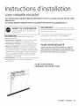
Instructions d'instailation
Lave-vaisse e encastr
Pourtoute question, appelez le 800.GE.CARES(800.432.2737) or consultez notre site internet" GEAp-
pliances.com.
AuCanada, appelez le 1.800.561.3344ou consultez le site internet www.geappliances.ca
AVANT DE COMMENCER
LISEZCESINSTRUCTIONSENTII_REMENTET
ATTENTIVEMENT.
M PORTANT - Respecteztouslescodeset
reglementsenvigueur.
. Remarque pourl'installateur- Assurez-vousde remettre
ces instructions a I'utilisateur et a I'inspecteur local.
Remarque pour I'Utilisateur- Conservez ces instructions
avec votre notice d'utilisation pour toute r6f@ence future.
Niveau de competence - L'installation de cet appareil
demande des connaissances de base en m6canique, en
61ectricit_ et en plomberie. L'installateur est responsable de
I'installation correcte de I'appareil. La panne de I'appareil
due (3une mauvaise installation n'est pas couverte par
la garantie GEElectrom_nagers. Veuillez consultez les
informations sur la garantie.
D_lai d'ex_cution - 1 a 3 heures. Lespremieres installations
demandent plus de temps que les installations de
remplacement.
IM PORTANT - Lelave-vaisselleDOIT@treinstall6
de mani@e a permettre le retrait ult@ieur de I'enceinte afin de
permettre toute intervention.
Sivous recevez un lave-vaisselle endommag@, contactez
imm6diatement votre vendeur ou votre installateur.
Accessoires en option - Consultez le Manuel d'Utilisation pour
les ensembles de panneaux sur mesure.
POURVOTRESECURITE
Lisez et respectez tous les AVERTISSEMENTSet MBES EN
GARDEdorm,s dans cette notice. II est recommand_ de
porter des gants et des lunettes de s_curit_ ou des lunettes
_tanches lors de Pinstallation de cet appareil.
LIRE ATTENTIVEMENT.
CONSERVEZ CES INSTRUCTIONS
31-30264 09/23/10 GE

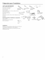
Preparation pour I'installation
OUTILLAGE NI_CESSAIRE •
CI Tournevis cruciforme No. 2
CI Tournevis 6 t_te plate
CI Tournevis Torx T20
CI CI_6 molette
CI CI6anglaise (!/2po [12 mm] ou 5/8po [16 mm])
CI Ruban 6 mesurer
CI Lunettes de s6curit6
CI Torche
CI Seau pour collecter I'eau Iors de la vidange du tuyau
CI Gants
CI Niveau
Pour les premieres installations uniquement"
CI Coupe-tube
CI Perceuse et forets appropri6s
CI Sciecylindrique _-_
CI_ anglaise
-___._ Nivea u
Tourne_e'_ Tournevis Tor-'_
plate taille T 20
Torche
CI6 6 molette
Lunettes de s_curit_
Ruban 6 mesurer
Seau forets
Gants
MATERIAU×
C! Tube en cuivre de diam_tre externe minimum de 3/8 poet
d'une Iongueur suffisante pour votre installation
C! Robinet de sectionnement et accessoires pour le tube
d'alimentation d'eau

Preparation pour I'installafion
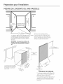
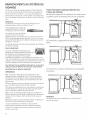
MESURE DE L'ENCEINTE DU LAVE-VAISSELLE
®
90°
2-4po
50 -!05 mm
Ouverture pour le
cablel-1/2po DIA.
maxDIA 44 mm
O
• W_6}Omn_ ..
* La largeur r@elledu lave-vaisselle......... ......perme_-,__,, _ u t
I'installation dans une ouverture de 23-5/8
po. Si le panneau en acier inox en option
(ZXSS9900)est utilis6, rouverture doit @tre
de 24 po.
Assurez-vous que les bords de
I'ouverture pour le cable soient bien
lissespour 6viter tout dommage aux
tuyaux d'alimentation et d'6vacuation
ainsi qu'au cable d'alimentation.
REMARQUE : Une ouverture de 24 po de-
mande des travaux suppl_mentaires sur
I'int_rieur de I'ouverture pour un aspect
fini.
La porte du lave-vaisselle
est montr6e sans panneau
sur mesure ou sans pan-
neau en kit.
34-!/4po 6 36-
E !/8po
oo I70-920 mm
::0
J
sApo
d'6paisseur19
mm
*** Le panneau sur mesure doit avoir un
d@gagementde 1/8 po min de chaque
c6t6 pour une bonne installation dans
I'enceinte.
PANNEAU SUR MESURE
** La hauteur doit _tre de 28-3/8 po IVllN
- et de 31 V2po MAXpour s'adapter aux
diff@entes hauteurs de plinthe.

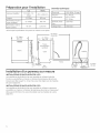
Pr pa ration Donn_es techniques
Hauteur (ragluble) 857 to 908 mm
Lurgeur 600 mm
Profondeur (Inclut le 581 mm
tuyuu suraleva)
Profondeur uvec 16 1266 mm
porte ouverte
pour I'installation
U.S. Metric
33-3/4po - 35-
3/4po
23-3/8po
22-7/8po*
49-3/4"
*N'inclut pus lu profondeur d'un porte sur mesure ou en option.
Electricit6 120V,60Hz, 15 amp
Pression 4.2-140 psi,
d'ulimentution : 0.03-1.0 MPG,
0.3-10 Bar
El#ment chuuf- 1200 watt
runt :
L
Charge max 1300 watt
23-3/8po _1600 mm
O
O_
r_
i
t_
r-r3
Avant o
O_
r_
i
r_
E
E
oo
O
Oh
,ED
Lr3
OO
O
C)_
_c_
.°T
-.1- L!h
Ln
49-3/4po
1266 mm
22-7/8po
m 581 mm
sur#lev i
Cat#
]-i 2po -
50 mm
i
3-1/4p
85 mm
Installation d'un panneau sur mesure
INSTALLATIONS D'UNE PUNTHE DE 4 PO
Les installations de plinthe de 4po sont possibles en utilisant la plinthe
fournie ou une plinthe sur mesure. La hauteur des panneaux de porte sur
mesure peut allerjusqu'5:31-1/2 po max. pour _tre align# avec les meubles
de cuisine adjacents.
INSTALLATIONS D'UNE PLINTHE DE 6 PO
Les installations de plinthe de 6po sont possibles en utilisant uniquement
une plinthe sur mesure. La hauteur des panneaux de porte sur mesure peut
allerjusqu'a 28-3/8 po max. pour _tre align6 avec les meubles de cuisine
adjacents.
2-3/4po
70 mm
La page est en cours de chargement...
La page est en cours de chargement...
La page est en cours de chargement...
La page est en cours de chargement...
La page est en cours de chargement...
La page est en cours de chargement...
La page est en cours de chargement...
La page est en cours de chargement...
La page est en cours de chargement...
La page est en cours de chargement...
La page est en cours de chargement...
La page est en cours de chargement...
-
 1
1
-
 2
2
-
 3
3
-
 4
4
-
 5
5
-
 6
6
-
 7
7
-
 8
8
-
 9
9
-
 10
10
-
 11
11
-
 12
12
-
 13
13
-
 14
14
-
 15
15
-
 16
16
-
 17
17
-
 18
18
-
 19
19
-
 20
20
-
 21
21
-
 22
22
-
 23
23
-
 24
24
-
 25
25
-
 26
26
-
 27
27
-
 28
28
-
 29
29
-
 30
30
-
 31
31
-
 32
32


GE ZBD9900R00II Guide d'installation
- Catégorie
- Lave-vaisselle
- Taper
- Guide d'installation
dans d''autres langues
- English: GE ZBD9900R00II Installation guide
Documents connexes
Autres documents
-
KitchenAid KUDS01FKSS0 Guide d'installation
-
KitchenAid KUDI01DLBS6 Guide d'installation
-
KitchenAid KUDS03FSWH3 Guide d'installation
-
Kenmore 66513206K902 Guide d'installation
-
-
KitchenAid KUDI01ILBT3 Guide d'installation
-
KitchenAid KUDK03FTSS1 Guide d'installation
-
IKEA IUD9750WS0 Guide d'installation
-