Bosch SGE63E06UC/28 Guide d'installation
- Taper
- Guide d'installation

A
_uJ
€_
C_
Go
Lt_
c_
C_
€_
c_
€_

A Important Safety instructions
To avoid possible injury or property damage, OBSERVE
ALL WARNINGS AND CAUTIONS.
These instructions are intended for use by qualified
installers only. The dishwasher must be installed by a
qualified service technician or installer.
, In addition to these instructions, the dishwasher
shall be installed to meet all electrical and plumbing
codes and ordinances (both national and local).
Read these installation instructions completely and
follow them carefully, They will save you time and ef-
fort and help to ensure safety and optimum dishwasher
performance.
Inspect the Dishwasher
After unpacking the dishwasher and prior to installation,
thoroughly inspect the dishwasher for possible freight or
cosmetic damage. Report any damage immediately.
Cosmetic defects must be reported within 30 days of
installation.
NOTE: Do not discard any bags or items that come
with the original package until after the entire installation
has been completed.
IMPORTANT
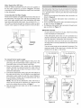
, The dishwasher drain hose must be installed with
a portion of it at least 20" (508mm) off the cabinet
floor; otherwise the dishwasher may not drain prop-
erly.
This dishwasher is intended for indoor residential
use only, and should not be used in commercial
food service establishments.
NEW INSTALLATION - If the dishwasher is a new
installation, most of the work must be done before
the dishwasher is moved into place.
REPLACEMENT - If the dishwasher is replacing
another dishwasher, check the existing dishwasher
connections for compatibility with the new
dishwasher, and replace parts as necessary.
, This appliance has been found to be in compliance
with CAN/CSA-C22.2 No. 167/UL 749. It is the
responsibility of the owner and the installer to
determine if additional requirements and standards
apply in specific installations.
, Not for outdoor use.
2

A
Avoiding General Hazards
Do not use the dishwasher until it is completely
installed. When opening the door on an uninstalled
dishwasher, carefully open the door while supporting
the rear of the unit. Failure to follow this warning can
cause the dishwasher to tip over and result in serious
injury.
Before installing the "L"-shaped supplied countertop
mounting brackets (select models), decide which
method will be used to secure the dishwasher into its
opening. Once these mounting brackets are installed
on the dishwasher, removing them is difficult and will
damage the mounting brackets and the dishwasher.
in some conditions, hydrogen gas can form in a hot
water system that has not been used for weeks.
Hydrogen gas is explosive.
Before filling a dishwasher from a system that has
been off for weeks, run the water from a nearby faucet
in a well ventilated area until there is no sound or evi-
dence of gas.
Temperatures required for soldering and sweating will
damage the dishwasher's base and water inlet valve.
If plumbing lines are to be soldered or sweated, keep
the heat source at least 6 inches (152.4 mm) away
from the dishwasher's base and water inlet valve.
Make sure electrical work is properly installed. There
should be no loose electrical connections. Ensure all
electrical connections are properly made.
The customer has the responsibility of ensuring that the
dishwasher electrical installation is in compliance with
all national and local electrical codes and ordinances.
The dishwasher is designed for an electrical supply
of 120V, 60 Hz, AC, connected to a dishwasher-
dedicated, properly grounded electrical circuit with a
fuse or breaker rated for 15 amps. Electrical supply
conductors shall be a minimum #14 AWG copper only
wire rated at 75°C (167°F) or higher.
This appliance must be connected to a grounded metal,
permanent wiring system, or an equipment-grounding
conductor must be run with the circuit conductors and
connected to the equipment-grounding terminal or
lead on the appliance. Do not use extension cords.
Avoiding Plumbing/Scalding Hazards__ [_
Do not perform any work on a charged hot water line.
Serious injury could result. Only qualified plumbershould
perform plumbing work. Do not attempt any work on
the dishwasher hot water supply plumbing until you
are certain the hot water supply is shut off.
Removing any cover or pulling the dishwasher from the
cabinet can expose hot water connections, electrical
power and sharp edges or points. Handle with care.
Avoiding Electrical Shock/Fire Hazards
Do not allow the electrical and water supply lines to
touch. Separate channels are provided under the
dishwasher.
Do not work on an energized circuit. Doing so could
result in serious injury or death. Only qualified electri-
cians should perform electrical work. Do not attempt
any work on the dishwasher electric supply circuit
until you are certain the circuit is de-energized.
Do not over tighten the 90 ° elbow. Doing so may
damage the water inlet valve and cause a water leak.
Temperatures required for soldering and sweating will
damage the dishwasher's water inlet valve. If plumbing
lines are to be soldered or sweated, keep the heat
source at least 6 inches (152.4 mm) away from the
dishwasher's water inlet valve.
Check local plumbing codes for approved plumbing
procedures and accessories. All plumbing should be
done in accordance with national and local codes.
These instructions depict an installation method for
stainless steel braided hose or PEX hot water supply
lines. If using copper tubing or other material for
water supply, defer to a licensed plumber for proper
installation.
3

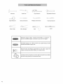
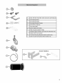
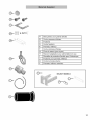
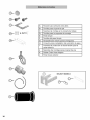
Hammer Hole Saw
F ............................. r_b)
Pipe Wrench Adjustable Wrench
Tape Measure
Slot Screwdriver
Phillips Screwdriver
1-20 Screwdriver
Wire Cutter
Wire Stripper
L©,
Level
Electrical Supply Cable - Minimum #14 AWG, 2 conductor, 1
ground, insulated copper conductors rated 75°C or higher.
Hot Water Supply Line - Minimum 3/8" O.D. copper tubing or metal
braided dishwasher supply line.
Shut-off valve and fittings appropriate for hot water supply line
(copper tubing/compression fitting, or braided hose).
UL listed conduit connector or strain relief is required ifyou attach
the field wiring directly to the terminal block.
4

_ I_::i_
A Extra Tall Item Sprinkler (See Use and Care Manual)
B Toe Panel Screws
C Mounting Brackets
D Mounting Bracket Screws
E Toe Panel (2 pieces)
F Toe Panel caps
G Screw Clamp (for hose)
H Water Supply Adaptor Fitting
I Flexible Edge Protector Grommet for electrical wire
J Rubber Drain Hose Adaptor
K Toe Panel Mounting Brackets (select models only)
L Outer toe panel (3rd piece) Select models only.
SELECT MODELS
H JHH_
0
5

Avoid Scalding or Electrical Shock Hazard7 /
Make sure the water supply and electrical supply ar_
shut off before installation or service, j
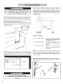
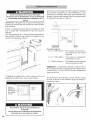
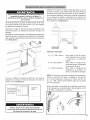
After locating the proper place for your new dishwasher,
you will need to make any required openings to allow for
passage of the water, drain and electrical line. In order to
avoid interference with the dishwasher when sliding it into the
cabinet, place your openings within the dimensions shown
in Figure 3 below.
NOTE: This dishwasher is designed to be enclosed on the top
and both sides by standard residential kitchen cabinetry.
Select a location as close to the sink as possible for easy
access to water supply and drain lines.
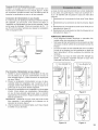
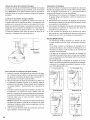
For proper dishwasher operation and appearance, ensure
that the enclosure is square and has the dimensions shown
in Figure 1 below.
E
If the dishwasher is to be installed in a corner, make sure that
there is adequate clearance to open the door. See Figure
2 below.
Checkclearance[
between /
dishwasherdoor / Countertop
andwall l
J J// I I \
Required Openings:
41/4"x 2" (108 x 52mm) -
4" x 2" (100 x 50mm) -
11/4"(32mm) diameter -
To pass the included electrical
supply junction box through to
an adjacent cabinet
To pass the included water
supply line toward the water
supply
To pass the dishwasher
drain hose toward the drain
connection
NOTE: If the incoming electric supply, water supply and
drain connections are all in the same cabinet, the one
4V4"x 2" (108 x 52mm) hole will be large enough for all three
to pass through.
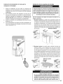
Before sliding the dishwasher into the cabinet, remove the
hose clip at the back of the dishwasher as shown below
and discard.
Avoid Electrical Shock/Fire Hazard
Do not allow the electrical and water supply lines
to touch.
E
................... i............................ i...........
6

ELECTRICAL PREPARATION
Avoid Electrical Shock Hazard
Do not work on an energized circuit. Doing so
could result in serious injury or death. Only
qualified electricians should perform electrical
work. Do not attempt any work on the dishwasher
electric supply circuit until you are certain the
circuit is de=energized.
Avoid Fire Hazard
Make sure electrical work is properly installed.
Only qualified electricians should perform
electrical work.
Electrical Supply
The customer has the responsibility of ensuring that the
dishwasher electrical installation is in compliance with all
national and local electrical codes and ordinances. The
dishwasher is designed for an electrical supply of 120V,
60 Hz, AC, connected to a dishwasher-dedicated, properly
grounded electrical circuit with a fuse or breaker rated for 15
amps. Electrical supply conductors shall be a minimum #14
AWG copper wire rated at 75°C (167°F) or higher.
Avoid Fire Hazard
Make sure there are no loose electrical connections.
Make sure all electrical connections are properly
made.
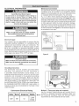
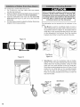
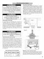
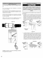
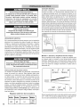
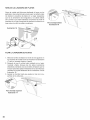
Electrical Connection
The dishwasher electrical supply junction box and dedicated
receptacle must be mounted in an accessible cabinet
adjacent to the dishwasher (do not mount the junction box
or receptacle behind the dishwasher). You will need a
41/4'' x 2" (108 x 51mm) opening throught the cabinet in
order to pass the junction box through (see Figure 4). If the
opening is made through wood, sand it smooth. Ifthe opening
is made through metal, use the included protective grommet
or other approved method to protect wiring from damage.
Use the four screws included (or appropriate fastener) in the
parts bag to securely mount the junction box so that it can
be easily accessed (see Figure 4). The electrical supply can
be connected in two ways:
::'Pla'c'°e'1
Id Wiring
Bectdcal Supply} / /
L
Figure 4
junction box and I
three prong plug I
are included 1
with dishwasher.//
Figure 5
Grounding Instructions
The dishwasher must be properly grounded before
operating. This appliance must be connected to
a grounded metal permanent wiring system, or an
equipment grounding conductor must be run with the circuit
conductors and connected to the equipment grounding
terminal or lead on the dishwasher. Make sure that the
dishwasher is connected to a suitable ground in compliance
with all local codes or, in the absence of a local code, with
the NATIONAL ELECTRICAL CODE in the United States or
the CANADIAN ELECTRIC CODE C22.1-1atest edition in
Canada as well as any provincial/state or municipal or local
codes that apply.
Dishwasher Electrical Rating
Volts Hertz Amperes Watts
120 60 12 1,300
(max)
Method A - Three prong plug and receptacle
Use the included three-prong plug and junction box to
connect to a dedicated household receptacle. Make sure
the household receptacle meets the electrical supply
requirements as well as national and local codes.
7

To
1.
,
,
,
,
,
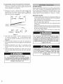
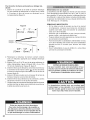
permanently connect to household or field wiring:
Remove the dishwasher electrical supply junction box
cover and connect to the power supply cord from the
house installation, (see Figure 5).
Remove 2" to 3" (51 - 76mm) of the outer casing of the
household or field supply wiring as shown in Figure 6.
Remove 3/8" to 1/2" (10 - 13mm) of the insulation from
each wire as shown in Figure 6.
2"- 3" 11
(51mm - 76mm). I
3/8"-1/2" I I
(10mm - 13ram)
Figure 6
Insert the bare copper or green wire(ground) to the
"G" ground connection "___L_" of the terminal block
and securely tighten the terminal block screw (see
Figure 5).
Insert the white (neutral) wire to the "N" connection of
the terminal block and securely tighten the terminal block
screw.
Insert the black(hot) wire to the "L" connection of the
terminal block and securely tighten the terminal block
screw.
Check all electrical connections to make sure they are
secure and then attach the junction box cover with the 4
screws.
Avoid Electrical Shock Hazard
To avoid possible injury or property damage,
care should be exercised when the dishwasher is
installed or removed to reduce the likelihood of
damage to the power cord.
Hot Water Supply
The hot water heater should be set to deliver approximately
120° F (49° C) water to the dishwasher. Water that is too
hot can cause some detergents to lose effectiveness. Lower
water temperatures will increase run times. The hot water
supply pressure must be between 15 - 145 psi (1 - 10 bar).
IMPORTANT NOTES:
If using a solder joint instead of a compression fitting, be
sure to make all solder connections before connecting the
water supply line to the dishwasher.
Make sure there are no sharp bends or kinks in the water
line that might restrict water flow.
Always use the appropriate seal when making plumbing
connections.
Before connecting the water supply line to the dishwasher,
flush the incoming water line for approximately 5 minutes
to clear any foreign material.
Turn on the water supply and check for leaks after
connections are made.
Avoid Scald Hazard
Do not perform any work on a charged hot water
line. Serious injury could result. Only qualified
plumbers should perform plumbing work. Do not
attempt any work on the dishwasher hot water
supply plumbing until you are certain the hot water
supply is shut off.
Temperatures required for soldering and sweating
will damage the dishwasher. If plumbing lines
are to be soldered or sweated, keep the heat
source at least 6 inches (152.4 mm) away from
the dishwasher.
8

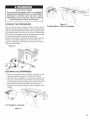
Water Supply Shut Off Valve
Install an easily accessible shut-off valve (not supplied) in
the hot water supply line, as shown in Figure 7. All solder
connections must be made before the water line is connected
to the dishwasher.
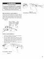
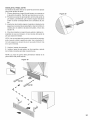
Connecting the Hot Water Supply
There are two plastic corrugated hoses that exit the back of
the dishwasher. The larger hose, with the brass fitting on the
end, is the water supply hose to the dishwasher (the other
hose is the dishwasher drain hose). You will need a 3"x 13/4''
(76 x 45mm) opening through the cabinet to pass the dish-
washer water supply line through toward the shut off valve.
Figure 7
To connect the hot water supply:
1. Assemble the water supply adaptor fitting from the
parts bag onto the dishwasher water supply hose. This
connection does not require Teflon brand tape.
2. Pass the dishwasher water supply line with attached
adaptor through the opening toward the water shut off
valve. Take care not to allow the hose to kink or twist
behind the dishwasher.
3. Connect the dishwasher water supply line with adaptor to
the water shut off valve. You will need to use an approved
dishwasher water supply line with the correct fittings for
this connection. Always use the appropriate seal when
making plumbing connections.
NOTE: The end of the dishwasher water inlet hose is
heavy and will need to be supported. It is best to lay the
end on the cabinet floor as shown in Figure 7.
4. After all connections are made, turn on the hot water and
check for leaks.
The dishwasher drain hose may be connected to the house-
hold or field drain plumbing in one of four ways. You will need
a 1t/4'' diameter hole in order to pass the drain hose through
the cabinet.
1 Directly to the undersink dishwasher drain connection, as
shown in Figure 8.
2 Directly to a disposer dishwasher drain connection, as
shown in Figure 9.
3 To the undersink dishwasher drain connection through an
air gap, as shown in Figure 10.
4 To a disposer dishwasher drain connection through an air
gap, as shown on Figure 11.
iMPORTANT NOTES:
If local ordinance require an air gap, install it according
to the manufacturer's instructions.
If the dishwasher drain hose is to be connected to a
disposer dishwasher drain connection, remove the plug
from the disposer's dishwasher drain connection.
The dishwasher drain hose must have one place along
its length that is securely attached 20 inches above the
cabinet floor.
The drain hose length can be extended if necessary. The
maximum length of the drain hose, including the hose
leading to the air gap, is 150 inches.
_, • • j
Figure 8
Figure 10
Non-Metallic Tie
Figure 9
Figure 11
9

For a large port, use the drain hose as it is.
1. For a small port, insert the rubber drain hose adaptor
into the drain hose end.
2. Obtain the Rubber Drain HoseAdaptor spring clamp from
the Dishwasher Installation Kit (do not substitute).
3. Insert the dishwasher drain hose into the end of the
drain hose (see Figure 12). Be sure to fully insert the
drain hose.
4. Use the clamp provided to attach the Rubber Drain Hose
Adaptor to the house plumbing
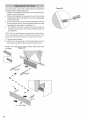
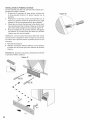
Before installing the supplied countertop mounting
brackets, decide which method of securing the
dishwasher into its enclosure will be used. Once the
mounting brackets are installed on the dishwasher,
removing them is difficult and will damage the
mounting brackets and the dishwasher.
The dishwasher can be secured into its enclosure in two
ways:
1. Top Mount is used for countertops made of wood or
other materials that can easily drilled. Orient the mount-
ing brackets as shown in Figure 14, and position the two
small tabs on the mounting brackets over the two slots
on the dishwasher's front corners. Push the mounting
brackets down firmly to insert the tabs into the slots.
Figure 12
Figure 13
Top Mount
Figure 14
,
Side Mount is used for countertops made of marble,
granite, or other very hard materials that cannot be easily
drilled. Bend the mounting brackets along the small
holes and in the same direction as the two small tabs.
Orient the mounting brackets as shown in Figure 15, and
position the two small tabs on the mounting brackets
over the two slots on the dishwasher's front corners.
Push the mounting brackets down firmly to insert the
tabs into the slots.
Figure 15
Side Mount
10

Avoid Tip Over Hazard
Do not use the dishwasher until it is completely
installed. When opening the door on an uninstalled
dishwasher, carefully open the door while
supporting the rear of the unit. Failure to follow
this warning can result in serious injury.
~12mm/0.5 ''
LEVELING THE DISHWASHER
The unit should now be ready to slide into the cabinet
opening. Toavoid scratching the floor, use floor protection and
caution when sliding the dishwasher into the cabinet. Make
sure that the hoses and cords do not bunch up behind the
unit or kink as you slide the unit back. Make certain to slide
the unit into place before raising the leg levelers.
Level the dishwasher horizontally by turning feet clockwise
to raise or counter-clockwise to lower front of the unit.
Level the dishwasher vertically by turning center screw to
raise or lower the back.
Figure 16
Figure 18
For Side Mount - Stone Countertop
i
SECURING THE DISHWASHER
1. Drive the mounting screws through the holes in the
mounting brackets as shown for Top or Side Mount.
2. After the unit is installed in the enclosure, leveled and
secured, lock the two front leg levelers in place by driving
the enclosed leg leveler locking screws into each screw
boss located in front of the levelers. See Figure 18.
3. Tighten screws until they are flush with the surface of the
bosses.
02
mm/0.1"
For Top Mount - Wooden
Figure 17
11

,
Your dishwasher comes with a three-piece toe panel(select
models) to allow height adjustment.
1. Position the slotted rear toe panel on the dishwasher first.
Allow it to rest on the floor.
2. Position the mating front toe panel on top of the rear toe
panel allowing the angled edge to rest on the mating edge
of the dishwasher.
3. Drive the two black screws (included) through the hole in
the toe panel to secure. Use the supplied screws to avoid
damaging the dishwasher. See Figure 19.
4. For models with outer toe panel (3rd piece) slide the
brackets (A) provided, into the slots of the toe panel you
just attached.
NOTE: Once you determine the correct position for the brackets,
remove the bracket and bend the metal tab. See Figure 20. This
ensures that the toe panel wont slide in further than you need.
5. Re-insert the brackets.
6. Attach the outer toe panel (L) onto the brackets and drive
the screws provided in place to secure the toe panel.
NOTE: The rubber piece should remain behind the outer
toe panel. Figure 19
,,lr
S
%
%
%
A %
Figure 20
12

Yourdishwasherrequiresno specialcareotherthan
thatdescribedintheCareandMaintenancesectionof
theUseandCareManual.Ifyouarehavinga problem
withyourdishwasher,beforecallingforserviceplease
refer to the Self Help sectionin the Use and Care
Manual.Ifserviceisnecessary,contactyourdealeror
installeroranauthorizedservicecenter.
Do notattemptto repairthe applianceyourself.Any
workperformedby unauthorizedpersonnelmayvoid
thewarranty.If you are havinga problemwith your
dishwasherandare notpleasedwiththe serviceyou
havereceived,pleasetakethefollowingsteps(in the
order listedbelow) untilthe problemis correctedto
yoursatisfaction:
1. Contactyour installeror the AuthorizedService
Contractorinyourarea.
2. E-mail us. See your Use and Care Manualfor
instructions.
3. Writeusattheaddressbelow:
BSHHomeAppliances,Corp.
5551McFaddenAvenue
HuntingtonBeach,CA92649
4. CallusattheCustomerServicephonenumber:
1-800-944-2904
Pleasebesuretoinclude(ifyouarewriting),orhave
available(ifyouarecalling),thefollowinginformation:
, Modelnumber
, Serialnumber
, Dateoforiginalpurchase
, Datetheproblemoriginated
, Explanationoftheproblem
, Daytimephonenumberwhereyoucanbereached.
Pleasemakeacopyofyourinvoiceandkeepitwiththis
manual.Thecustomermustshowproofofpurchaseto
obtainwarrantyservice.
13

lnstructions de s curit
Pour eviter tout dommage a la propriet6
ou des blessures OBSERVER TOUSLES
AVERTISSEMENTS.
Ces instructions sont destinees a I'utilisation par
un installateur qualifie seulement. Ce lave-vaisselle
doit _tre installe par un technicien ou un installateur
qualifie seulement.
En plus de ces instructions, le lave=vaisselle
doit _tre installe conformement aux codes et
reglementations electriques et de plomberie
(nationaux et Iocaux).
Lire et observer attentivement toutes les instructions
d'instatlation. Ceci permettra d'economiser temps
et argent tout en assurant la securit6 et un
rendement optimum du lave=vaisselle.
IMPORTANT
• Le tuyau de drainage du lave=vaisselle doit
@re installe avec une portion a au moins 20
po (508 mm) au=dessus du plancher d'armoire,
autrement le lave=vaisselle ne pourra drainer
adequatement.
• Ce lave=vaisselle est destine a un usage
residentiel seulement et non pour un usage
commercial.
• NOUVELLE INSTALLATION - s'il s'agit
d'une nouvelle installation, tout le travail de
construction doit @re fait avant d'installer le
lave=vaisselle.
• REMPLACEMENT- dans ce cas, v@ifier si les
connexions existantes sont compatibles avec
celle du nouveau lave=vaisselle et remplacer
les pieces au besoin.
• Cet appareil est conforme aux normes CAN/
CSA-C22,2 n°167/UL 749. II incombe
I'installateur et au proprietaire de determiner
si des exigences additionnelles s'appliquent
I'installation specifique.
• N'est pas destine a une utilisation
I'exterieur.
importantes
V6rifier le lave=vaisselle
Apres avoir deball6 I'appareil et avant I'installation,
s'assurer qu'il n'y a pas de dommages esthetiques
ou causes pendant le transport. Rapporter tout
dommage immediatement. Les dommages
esthetiques doivent _tre rapportes dans un delai
de 30 jours suivant I'installation.
REMARQUE : ne pas jeter les sacs ni I'emballage
tant que I'installation n'est pas complet6e.
14

Risques d'ordre g6n6ral
Ne pas utiliser le lave-vaisselle avant que 'installation
ne soit completement terminee. Pour ouvrir la porte
d'un lave-vaisselle encore non installe, il faut le faire
soigneusement en soutenant I'arriere du lave-vais-
selle. Le lave-vaisselle peut en effet tomber en avant
si cet avertissement n'est pas respecte et cela peut
causer de graves degats.
Avant I'installation des fixations en forme de <<L >)(pour
certains modeles), il faut choisir la methode qui sera
utilisee pour I'ouverture du lave-vaisselle. Une fois que
ces fixations sont installees sur le lave-vaisselle, il est
difficile de les retirer et cela risque d'endommager les
fixations et le lave-vaisselle.
Sous certaines conditions, le systeme d'eau chaude
peut emettre du gaz hydrogene si le lave-vaisselle
n'a pas ete utilise pendant plusieurs semaines. Le
gaz hydrogene est un gaz explosif. Avant de refaire
fonctionner le lave-vaisselle apres une Iongue periode,
faire couler I'eau du robinet le plus proche dans une
zone bien ventilee jusqu'a ce qu'il n'y ait plus aucun
bruit de gaz ou toute autre preuve de sa presence.
Les temperatures necessaires pour souder et ex-
suder risquent d'endommager la base et la soupape
d'admission d'eau du lave-vaisselle. Si la tuyauterie
a besoin d'une soudure ou d'une exsudation, placer
la source de chaleur a au moins 6 po (152,4 mm) de
la base et de la soupape d'admission d'eau du lave
vaisselle.
Vouloir retirer un des couvercles ou vouloir deplacer le
lavevaisselle de son emplacement peut endommager
les tuyaux d'eau chaude et I'alimentation electrique.
Effectuer ces manipulations avec soin.
Risques d'electrocution et d'incendie
Les cables electriques et les tuyaux d'alimentation
en eau ne doivent pas etre en contact. Des conduits
independants sont prevus a cet effet sous le lave-
vaisselle.
Effectuer des travaux electriques Iorsque le courant
est ouvert peut provoquer des blessures graves
ou la mort. Seul un electricien qualifie peut realiser
des manipulations electriques. N'effectuer aucune
manipulation electrique sur le lave-vaisselle tant que
le courant n'est pas clairement hors tension.
S'assurer que les travaux electriques soient
correctement realises. II ne doit y avoir aucun cable
electrique mal fixe et aucun raccordement electrique
mal realis&
Le client a la responsabilite de verifier que I'installation
electrique du lave-vaisselle soit conforme aux normes
electriques nationales et regionales. Le lave-vaisselle
a ete con_u pour fonctionner avec une alimentation
electrique de 120V, 60Hz, c.a., et doit etre branche
a un circuit electrique adapte au lave vaisselle
correctement relie a la terre et protege par un fusible
de 15 amperes. Les conducteurs electriques doivent
etre composes de ills en cuivre n°14 AWG minimum
ayant une resistance thermique minimale de 75°C
(167°F).
Ce lave-vaisselle doit etre relier a la terre soit en le
connectant au support metallique qui est relie a la terre
soit en branchant la prise du terre du lave-vaisselle a
une prise de courant appropriee, elle- m_me reliee a
la terre. Ne pas utiliser de rallonge.
Risques de brQlure_
Ne pas effectuer de travaux de plomberie sur un tuyau
rempli d'eau chaude. II y a des risques de blessures
graves. Seul un plombier qualifie peut realiser des
manipulations de plomberie. N'effectuer aucun travail
de plomberie sur le lave-vaisselle tant que I'arrivee
d'eau chaude n'est pas clairement fermee.
Ne pas serrer trop fort le coude de 90 °. Cela peut en-
dommager la soupape d'admission d'eau et provoquer
une fuite de I'eau.
Les temperatures necessaires pour souder et exsuder
dsquent d'endommager la soupape d'admission
d'eau du lave-vaisselle. Si la tuyauterie a besoin
d'une soudure ou d'une exsudation, placer la source
de chaleur a au moins 6 pouces (152,4 mm) de la
soupape d'admission d'eau du lave-vaisselle.
II est necessaire de verifier les normes relatives aux
travaux de plomberie pour toute installation. Tout tra-
vail de plomberie doit etre conforme avec les normes
nationales et regionales.
Ces instructions sont relatives a une methode
d'installation utilisant des tuyaux d'alimentation en
acier inoxydable tresse et des tuyaux d'eau chaude
PEX. Si la tuyauterie est en cuivre, ou tout autre
materiau, pour I'alimentation en eau, il fau faire appel a
un plombier qualifie pour une installation appropriee.
15

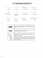
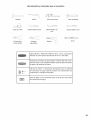
Marteau
Scie-cloche
F ............................. __b)
Cl6 a tuyau
Cl6 r6glable
Ruban a mesurer Tournevis &
lame plate
Tournevis Phillips
Tournevis -[-20
Coupe-ill
Outil & d6-
nuder
[©,
Niveau
4
C&ble d'alimentation 61ectrique - minimum #14AWG, 2 conduc-
teurs, 1 mise a la terre, conducteurs en cuivre isol6s cot6 75 °C
ou plus
Canalisation d'alimentation en eau chaude - tube en cuivre ou
en m6tal tress6 D.E. 3/8 po maximum
Soupape d'arr6t et raccords appropri6s pour la canalisation
d'alimentation en eau chaude (tube en cuivre, raccord de com-
pression ou tuyau tress6)
Connecteur de conduit ou r6ducteur list6s UL, m_me si un
r6ducteur est inclus avec la bofte de jonction, un autre r6ducteur
peut _tre n6cessaire si I'onfixe le c&blage d'excitation directement
sur le bloc de bornes.
16

_ I_::i_
A Bras gicleur pour grands articles
B Vis du panneau inf@ieur
g Fixations
D Vis de fixations
E Panneau inf@ieur
F Vis du panneau inf@ieur
G Pince & ressort (pour tuyau)
H Raccord adaptateur pour alimentation en eau
I Rondelle de protection flexible pour fil electrique
J Fixations pour panneau inf@ieur
K Crochet et bande attache
L Panneau inf@ieur exterieur
SELECT MODELS
Y
(:D--oO
17

E_viterles brOlures et les chocs _lectriques. I
S'assurer que les alimentations en eau et @lectrique I
!
sont ferm_es avant d'effectuer rinstallation ou le|
service j
REMARQUE "cet appareil est congu pour etre encastr6 sur
le dessus et les c6t6s par des armoires de cuisine r6siden-
tielle standard.
Choisir un emplacement aussi pros que possible de 1'6vier
pour un acces ais6 & I'alimentation en eau et au tuyau de
drainage.
Pour une apparence et un fonctionnement appropri6s du
lave-vaisselle, s'assurer que I'espace est d'6querre eta les
dimensions indiqu6es a la figure 1..
Apr_s avoir trouv6 I'emplacement pour I'appareil, il faut faire
les ouvertures n6cessaires pour les canalisations en eau,
61ectrique et de drainage. Afin d'6viter toute interf@ence au
moment d'ins@er le lave-vaisselle, faire les ouvertures selon
les dimensions donn6es a la figure 3.
J J// I I \
Si I'appareil est install6 dans un coin, s'assurer qu'il y a un
d6gagement suffisant pour ouvrir la porte, figure 2.
Verifiere .ande
d6gagement / travail
entrela portedu J
lave-vaisselle /
etle tour [
Pour _viter le risque de choc _lectrique et
d'incendie
Ne pas laisser les canalisations d'alimentation
_lectrique et en eau entrer en contact.
Ouverture requise:
4V4"x 2" (108 x 52mm) -
3"x 13/4" (100 x 50mm) -
11/4"(32mm) diameter -
Pour passer la bofte de jonc-
tion comprise par une armoire
adjacente
Pour passer la canalisation
d'alimentation en eau
Pour passer letuyau de drainage
vers la connexion du drain
REMARQUE : si I'alimentation 61ectrique, celle de I'eau et
les connexions de drain sont toutes dans la m6me armoire,
I'ouverture de 4 % x 2 po (108 x 52 mm) sera suffisamment
large pour les trois.
Avant d'ins@er le lave-vaisselle en place, enlever la pince
du tuyau a I'arri@e du lave-vaisselle, tel qu'il est indiqu6 ci-
dessous et la jeter.
E
E
................... i........................... i...........
18

i_viterles chocs _lectriques
Ne pas travailler avec un circuit sous tension.
Cela peut causer de serieuses blessures ou la
mort. Seul un electricien qualifie peut effectuer
le travail electrique. Ne pas tenter de travailler
sur le lave-vaisselle tant que le circuit electrique
n'est pas coup&
leviter les risques d'incendie
S'assurer que I'alimentation electrique est
adequatement installee. Seul un electricien
ualifie eut effectuer le travail.
Alimentation 61ectrique
Le consommateur est responsable afin de s'assurer que
I'installation 61ectrique du lave-vaisselle est conforme aux
codes 61ectriques Iocaux et nationaux. Le lave-vaisselle est
congu pour une alimentation 61ectrique de 120V, 60Hz, c.a.,
branch6 sur un circuit 61ectrique mis & la terre ad6quatement
et d6di6 a I'appareil, avec un fusible ou un disjoncteur cot6
15 amperes. Les conducteurs electriques doivent _tre un
minimum de #14 AWG, fil de cuivre cote pour 75 °C (167
°F) ou plus.
I_viter les risques d'incendie
S'assurer que les connexions _lectriques ne
sont pas I_ches et qu'elles sont ad_quatement
branch_es.
instructions de raise a la terre
L'appareil dolt etre adequatement mis & la terre avant de
le faire fonctionner. Cet appareil dolt 6tre branche sur un
systeme de c&blage permanent en metal, mis a la terre ou
un conducteur de mise a la terre d'equipement dolt etre
branche sur la borne de mise a la terre d'equipement ou
le fil du lave-vaisselle. S'assurer que le lave-vaisselle est
branche sur une mise a la terre appropriee conformement
tousles codes ou en I'absence de codes Iocaux, avec le
CODE NATIONAL D'_:LECTRICITt_ aux E.-U. ou le CODE
D't_LECTRICITt_ DU CANADA, C22,1, derniere edition au
Canada ainsi qu'aux codes Iocaux, municipaux, provinciaux
qui s'appliquent.
Connexion 61ectrique
La bofte de jonction d'alimentation electrique du vaisselle
et la prise dediee doivent _tre install6es dans une armoire
adjacente au lave-vaisselle (ne pas les installer derriere
I'appareil). IIfaut une ouverture de 4 1/4 x 2 pc (108 x 51 mm).
Si I'ouverture est faite dans le bois, sabler le rebord ; si dans
le m6tal, utiliser la rondelle de protection ou autre m6thode
approuvee pour proteger le c&blage de tout dommage.
Utiliser les 4 vis comprises (ou attaches appropriees) du
sac de pieces pour fixer la bofte de jonction afin qu'elle soit
accessible (figure 4). L'alimentation electrique peut etre
branchee de deux fagons:
iiiii
Figure 4
/ /\\rd--wit_'
/ / _ junction box and
J/ _ I three prong plug
V " I are included
k with dishwasher,
Figure 5
Cote 61ectrique du lave=vaisselle
Volts Hertz Amperes Watts
120 60 12 1,300
(max)
M_thode A - fiche _ 3 broches et prise
Utiliser la fiche a 3 broches et la bofte de jonction comprise
pour brancher sur une prise residentielle dediee. S'assurer
que la prise residentielle repond aux exigences d'alimentation
electrique ainsi qu'au codes nationaux et Iocaux (figure 4).
19

Pour brancher de fa£on permanente au c_blage r@si-
dentiel :
1. Enlever le couvercle de la boite de jonction 61ectrique
du lave-vaisselle et d6brancher le cordon fourni & fiche
3 broches du bloc de bomes en d6vissant les vis
correspondantes (figure 6).
Figure 6
(51mm - 76mm). I
3/8" - 1/2"
(10mm - 13mm)
Alimentation en eau chaude
Le chauffe-eau dolt etre r6g16 pour donner une eau chaude
d'une temp@ature approximative de 120 °F (49 °C) pour le
lave-vaisselle. Si I'eau est trop chaude, le d6tergent perd de
son efficacit6 ;si elle est trop basse, la dur6e est prolong6e.
La pression de I'alimentation en eau chaude dolt etre entre
15 et 145 Ib/po2 (1 a 10 barres).
REMARQUES IMPORTANTES:
• Si I'on utilise un joint de soudure au lieu d'un raccord
compression, s'assurer que toutes les connexions
soud6es sont faites avant de brancher la canalisation
d'eau sur le lave-vaisselle.
• S'assurer que la canalisation en eau n'est pas coinc6e,
pinc6e ni pli6e ; cela obstrue le d6bit d'eau.
• Toujours utiliser les joints appropri6s au moment de faire
les connexions de plomberie.
• Avant de brancher la canalisation d'alimentation en eau
sur le lave-vaisselle, faire couler I'eau de la canalisation
pendant environ 5 minutes pour enlever tout objet
6tranger.
• Ouvrir I'alimentation en eau et v@ifier s'il y a des fuites
une fois les connexions termin6es.
2. Remplacer le r6ducteur de tension sortant compris
avec un r6ducteur appropri6 pour c_blage 61ectrique
r6sidentiel.
3. Enlever 2 a 3 po (51 a 76 mm) de la gaine ext@ieure du
c&ble d'alimentation, figure 5. Enlever 3/8 a ½ po (10
13 mm) de I'isolant pour chaque ill, figure 5.
4. Ins@er le fil de cuivre d6nud6 ou vert (mise a la terre) sur
la connexion G de mise a la terre ,,I,, du bloc de bornes
et visser en place de fagon s6curita]Te a la vis du bloc de
bornes (figure 6).
5. Ins@er le fil blanc (neutre) sur la connexion N du bloc de
bornes et visser a la vis du bloc de bornes.
6. Ins@er le fil noir (sous tension) sur la connexion L du bloc
de bornes et visser a la vis du bloc de bornes.
7. V@ifier toutes les connexions 61ectriques afin de s'assurer
qu'elles sont bien en place, puis remettre le couvercle sur
la boTte de jonction avec les 4 vis.
I_VITER LE RISQUE DE BRULURES
Ne pas travailler avec une canalisation d'eau
chaude, il peut en r_sulter de s_rieuses blessures.
Seul un plombier qualifi_ peut effectuer le travail.
II faut fermer la canalisation d'eau chaude.
La temperature requise pour une soudure peut
endommager le lave=vaisselle. Si la canalisation
doit Ctre soud_e, garder la source de chaleur a au
moins 6 po (152,4 mm) du lave-vaisselle.
€:viter les risques de chocs _lectriques
Pour @viter tout dommage a la propri@t@ ou
des blessures, faire trCs attention au moment
d'installer ou d'enlever le lave-vaisselle afin de
ne pas endommager le cordon d'alimentation.
2O
La page charge ...
La page charge ...
La page charge ...
La page charge ...
La page charge ...
La page charge ...
La page charge ...
La page charge ...
La page charge ...
La page charge ...
La page charge ...
La page charge ...
La page charge ...
La page charge ...
La page charge ...
La page charge ...
La page charge ...
La page charge ...
La page charge ...
-
 1
1
-
 2
2
-
 3
3
-
 4
4
-
 5
5
-
 6
6
-
 7
7
-
 8
8
-
 9
9
-
 10
10
-
 11
11
-
 12
12
-
 13
13
-
 14
14
-
 15
15
-
 16
16
-
 17
17
-
 18
18
-
 19
19
-
 20
20
-
 21
21
-
 22
22
-
 23
23
-
 24
24
-
 25
25
-
 26
26
-
 27
27
-
 28
28
-
 29
29
-
 30
30
-
 31
31
-
 32
32
-
 33
33
-
 34
34
-
 35
35
-
 36
36
-
 37
37
-
 38
38
-
 39
39


Bosch SGE63E06UC/28 Guide d'installation
- Taper
- Guide d'installation
dans d''autres langues
Documents connexes
-
Thermador SGE53U56UC/A5 Guide d'installation
-
Bosch SPE68U55UC Guide d'installation
-
-
Bosch Benchmark SHV89PW73N Manuel utilisateur
-
Bosch SGE68X55UC Guide d'installation
-
Bosch SHE43P02UC/59 Manuel utilisateur
-
Bosch SHE4AM16UC/05 Guide d'installation
-
Bosch SHV68R53UC/63 Guide d'installation
-