
Wattstopper
®
DLM - Analog Sensor Input Module
Installation Instructions • Instructions d’Installation • Instrucciones de Instalación
No: 24657 – 09/16 rev. 1
Catalog Number • Numéro de Catalogue • Número de Catálogo: LMIO-201
Country of Origin: Made in China • Pays d’origine: Fabriqué en Chine • País de origen: Hecho en China
SPECIFICATIONS
Voltage .....................................................................24VDC
Current Consumption ................................................. 20mA
Power Supply ........................Wattstopper Room Controller
Connection to the DLM Local Network ........... 2 RJ-45 ports
Environment ........................................For Indoor Use Only
Operating Temperature ....... 32° to 104°F (0° to 40°C)
Storage Temperature ......... 23° to 176°F (-5° to 80°C)
Relative Humidity ............. 5 to 95% (non condensing)
RoHS compliant, UL2043 Plenum rated
Patent Pending
This unit is pre-set for Plug n’ Go™ operation,
adjustment is optional.
For full operational details, adjustment and more features of
the product, see the DLM System Installation Guide provided
with Wattstopper room controllers, and also available at
www.legrand.us/wattstopper.
Installation shall be in accordance with all applicable
regulations, local and NEC codes. Wire connections shall
be rated suitable for the wire size (lead and building wiring)
employed.
For Class 2 DLM devices and device wiring: To be
connected to a Class 2 power source only. Do not reclassify
and install as Class 1, or Power and Lighting Wiring.
DESCRIPTION
The Lighting Management LMIO-201 device is a single channel low voltage analog sensor to DLM interface. It communicates a single
state of occupancy; however it may be driven by multiple physical sensors wired together. Usage of the device requires an auxiliary DC
power source such as a BZ power pack or AT-120/277 power supply.
MOUNTING AND WIRING
Installation shall be in accordance with all applicable regulations, wiring practices, and codes. Connect to a Class 2 power source only.
• Class 2 Device Wiring Only – Do Not Reclassify and Install as Class 1, 3 or Power and Lighting Wiring.
• Wire connections shall be rated suitable for the wire size (lead and building wiring) employed.
The LMIO-201 is UL2043 Plenum rated.
All connections to the LMIO-201 are Class 2 low voltage.
If code requires that the LMIO-201 be mounted in an enclosure, it can be mounted inside a 4” x 4” junction box, inside a 21/8” deep (or
deeper) 2-gang wall box, in a 3” or 4” octagonal box, or on a DIN rail inside a panel.
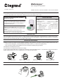
ATTACH THE LMRJ CABLE
The DLM local network uses free topology low voltage wiring. The LMIO-201 can connect anywhere on the DLM local network
Attach din rail clip Option 1: Attach to din rail Option 2: Mount to wall Inside a 2-gang J-box

2
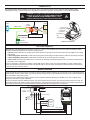
CONNECTIVITY
The illustration below show examples of free-topology wiring. The LMIO-201 device communicates to all other Digital Lighting
Management devices connected to the low voltage DLM Local Network, regardless of their position on the DLM Local Network.
CAUTION: TO CONNECT A COMPUTER TO THE DLM LOCAL
NETWORK USE THE LMCI-100. NEVER CONNECT THE DLM
LOCAL NETWORK TO AN ETHERNET PORT – IT MAY
DAMAGE COMPUTERS AND OTHER CONNECTED EQUIPMENT.
Buttons and Indicators
LED FUNCTIONALITY
“Status/Binding” LED blink patterns shall indicate occupancy, vacancy, and countdown when not in PnL mode. The following status
indications will be indentified per their respective specific pattern:
• LED off: indicates that either no analog control input is detected or analog control input has expired and the LMIO-201 time delay
has expired.
• LED blinking @1Hz (1x/second): indicates the analog sensor(s) time delay has expired and the LMIO-201 time delay has begun.
• LED blinking @3Hz (3x/second): indicates that the LMIO-201 is connected, but has no bindings.
• LED on solid: indicates that the LMIO-201 is connected, has bindings, and that the load(s) bound to it has been commanded per
the sensor mode configuration.
The red “Configuration” LED behaves similarly to other DLM devices. When in PnL the red LED will flash to confirm communication,
and the LED will flash periodically when DLM Local Network traffic is received. Solid red indicates problems with DLM Local Network
communication likely caused by wiring.
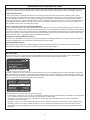
WIRING DIAGRAM
Wiring terminal naming is shown below. An auxiliary relay is provided inside the LMIO-201 for cycling power to any connected sensors if
desired. Simply wire the +24VDC power source to the sensors through the NC relay terminals and the LMCT-100 or LMCS software can
issue commands to cause relay cycling.
The LED’s of many Wattstopper analog occupancy sensors will blink noticeably allowing this capability to be used to identify which
sensors are wired back to a given LMIO-201.
The relay contacts are rated for 500mA at 24VDC. The ground terminal must be wired in common with the DC power source such as
BZ-150 Power Pack or AT-120/277 auxiliary DC power supply. The Sensor Detect signal wire from each of the sensors connected to a
given LMIO-201 must be wired to the Sensor Detect input of the LMIO-201 forming one zone of occupancy.
LMRJ Cables
Line Voltage
Room
Controller
Switch
LMIO-201
Sensor Interface
Low Voltage Wires
Loads
1
2
Input from Analog Sensors
RJ45 ports (2)
Configuration
push button
Status/Binding
LED
Wiring Terminals
Configuration LED
Relay Common
Relay Normally Closed (N.C.)
Ground
Sensor Detect
12248r1
Status/Binding
Not used
Not used
Not used
Not used
Connect to
DLM local network
NOT Ethernet
1
2 COM
3 N.C.
4 GND
5
6 SensDetect
7
8
9
10
Bind
Blue LEDs
+24VDC
Common
Red
White
Neut.
BZ-150
Grey
Black
Red
277VAC
Black
120VAC
Hot
Red
Orange
Control
Low Voltage Wires
Brown Blue
Any 3-wire
24VDC
Sensor

3
CONFIGURATION OPTIONS AND USE CASES
The LMIO-201 will implement most DLM Occupancy Sensor functionality including digital occupancy state, separate Normal Hours and
After Hours time delays, binding to multiple loads, preset on/off and scene actions, and writeable location and description properties.
Independent time delay
In order to have digitally configurable time delays to avoid using the analog sensor DIP switches after installation, set the analog
sensors’ time delays at product minimum. Analog occupancy sensor minimum time settings will vary. After the analog sensor delay(s)
expire the LMIO-201 will see the control input go low and begin its own countdown. The time delay will reset whenever the analog
control line goes high next, or, upon expiration will send “vacancy” messages to the loads bound to it. The delay of the analog sensor(s)
and the LMIO-201 itself are additive, so an LMIO-201 set to 15 minute delay connected to sensors set to a 1 minute minimum time
delay will initiate vacancy after 16 minutes without motion.
Push n’ Learn (PnL) procedure for binding LMIO-201
Since the Configuration Button is the only available button on the LMIO-201, PnL must be entered and loads cycled via another device.
The LMIO-201 can then be bound or unbound from any DLM load present on its local DLM Local Network. Pressing the button will bind
or un-bind the LMIO-201 to the currently active load. The “Status/Binding” LED indicates binding status (LED on indicates that the load
is bound). Once at least one bound load is active and PnL has been exited, pressing the button will de-activate all bound loads. When
all bound loads are inactive, pressing the button will activate all bound loads.
Procedure for clearing LMIO-201 bindings
When not in PnL, all bindings can be cleared by pressing and holding the Configuration Button for 10 seconds. Once the bindings are
cleared the “Status/Binding” LED will blink 3x to indicate the action was successful.
Sensor-dependent features
Walk Through, detection schemes (i.e. trigger/retrigger modes), and sensitivity must be set at each sensor using its DIP switches.
Reference the installation instructions for the product being used for exact feature support.
LMCT-100 USAGE
LMCT-100 Usage
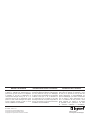
LMIO-201 settings can be accessed via LMCT-100 IR handheld remote through the “Sensor Configuration” menu using firmware
versions 5.19 or later. A new option has been added specifically for this purpose titled “Analog Occ Sensor”:
Entering the “Analog Occ Sensor” sub-menu will prompt the user to point to an available IR window on the local DLM room network to
which the LMIO-201 is connected. If at least one LMIO-201 is detected the next menu will display its current settings. If more than one
LMIO-201 is detected, the settings for the LMIO-201 with the highest serial number will be displayed first and the “NEXT” and “PRIOR”
options can be used to select which LMIO-201 is to be configured.
The following options are available for each parameter shown:
• Load Tracking: Choices are “Yes” and “No”, and determines whether the status of the LMIO-201 is maintained as a network status
only or whether occupancy/vacancy messages actually affect bound loads’ states.
• Follows AH: Choices are “Yes” and “No”, and determine whether After Hours transitions enforce secondary configuration
parameters and transition modes.
• NH Delay: Choices are a value in minutes from None to 30, and “Override” and sets the sensor timeout value for Normal Hours.
• AH Delay: Choices are a value in minutes from None to 30, and “Override” and sets the sensor timeout value for After Hours.
• After changing parameter settings, point the LMCT to the nearest IR window and press “Send” to commit the parameters to the
LMIO-201.
Sensor Configuration
Current Settings
Test Mode
S aved Configurations
Analog Occ Sensor
=
BAT
LMIO-201 010158054
Sensor is
Sensor is
Load Tracking:
Follows AH:
NH Delay:
AH Delay:
N EXT PRIOR
U noccupied
Normal Hours
<Yes>
<Yes>
< 15 min>
<5 min>
SEND DONE
Sensor Configuration
Current Settings
Test Mode
S aved Configurations
Analog Occ Sensor
=
BAT
LMIO-201 010158054
Sensor is
Sensor is
Load Tracking:
Follows AH:
NH Delay:
AH Delay:
N EXT PRIOR
U noccupied
Normal Hours
<Yes>
<Yes>
< 15 min>
<5 min>
SEND DONE

800.879.8585
www.legrand.us/wattstopper
No. 24657 – 09/16 rev. 1
© Copyright 2016 Legrand All Rights Reserved.
© Copyright 2016 Tous droits réservés Legrand.
© Copyright 2016 Legrand Todos los derechos reservados.
Wattstopper warranties its products to be free
of defects in materials and workmanship for a
period of five (5) years. There are no obligations
or liabilities on the part of Wattstopper for
consequential damages arising out of, or in
connection with, the use or performance of this
product or other indirect damages with respect
to loss of property, revenue or profit, or cost of
removal, installation or reinstallation.
Wattstopper garantit que ses produits sont
exempts de défauts de matériaux et de fabrication
pour une période de cinq (5) ans. Wattstopper
ne peut être tenu responsable de tout dommage
consécutif causé par ou lié à l’utilisation ou
à la performance de ce produit ou tout autre
dommage indirect lié à la perte de propriété, de
revenus, ou de profits, ou aux coûts d’enlèvement,
d’installation ou de réinstallation.
Wattstopper garantiza que sus productos
están libres de defectos en materiales y mano
de obra por un período de cinco (5) años. No
existen obligaciones ni responsabilidades por
parte de Wattstopper por daños consecuentes
que se deriven o estén relacionados con el
uso o el rendimiento de este producto u otros
daños indirectos con respecto a la pérdida
de propiedad, renta o ganancias, o al costo
de extracción, instalación o reinstalación.
WARRANTY INFORMATION INFORMATIONS RELATIVES À LA GARANTIE INFORMACIÓN DE LA GARANTÍA
-
 1
1
-
 2
2
-
 3
3
-
 4
4


wattstopper LMIO-201 DLM Analog Sensor Input Module Quick Start Guide de démarrage rapide
- Taper
- Guide de démarrage rapide
- Ce manuel convient également à
dans d''autres langues
Documents connexes
-
wattstopper C-Series Guide d'installation
-
-
wattstopper LMIN 104 Guide d'installation
-
-
wattstopper LMCT-100-2 Wireless Configuration Tool Mode d'emploi
-
wattstopper LMIO-301-U Guide d'installation
-
-
Autres documents
-
Legrand LMOR-102-Low Voltage Dual Relay Interface Guide d'installation
-
-
-
-