
OPERATION & INSTRUCTION MANUAL
(6kW, 9kW & 12kW Steam Generator & DeLuxe Control Panel)
Mandatory Reading Installation Updates- Page 4
Parts Request Info- Page 22
Note: SAVE SALES RECEIPT for proof of purchase/warranty

Table of Contents
Read Me First .................................................................................................................... 1
Safety Warnings ................................................................................................................. 2
Safety Warnings In French ................................................................................................. 3
Mandatory Reading ............................................................................................................ 4
Part 1: Steam Generator
User Instructions ................................................................................................................ 5
Choosing Your Type of Machine ........................................................................................ 5
Maintenance ...................................................................................................................... 5
Steam Generator Cleaning ............................................................................................. 5-6
Choosing a Proper Location ............................................................................................... 6
Steam Equipment Install Diagram ...................................................................................... 7
Installation of Steam line ................................................................................................. 7-8
Steam Generator Blueprint ................................................................................................ 9
Electrical Requirements ................................................................................................... 10
Power line Assembly ........................................................................................................ 10
Wiring Diagram ................................................................................................................ 11
Now Available .................................................................................................................. 12
Installation of the Top Light .............................................................................................. 12
Steam Generator Configuration ....................................................................................... 13
Troubleshooting Guide ..................................................................................................... 14
Instructions for Resetting Manual Hi-Limit ....................................................................... 15
Specifications ................................................................................................................... 15
Part 2: Control Panel
Cleaning Instructions ........................................................................................................ 16
Safety and Operation Information .................................................................................... 16
Blueprint for Control Panel ............................................................................................... 17
Installation of Controller .............................................................................................. 17-18
Temperature Detector Installation .................................................................................... 18
Control Panel Illustration .................................................................................................. 19
Keypad Operation ....................................................................................................... 19-20
Dual Keypad (if applicable) .............................................................................................. 21
Schematic ........................................................................................................................ 21
Part 3: Additional Information
Parts Request Instructions ............................................................................................... 22
Warranty Registration Instructions ................................................................................... 22
Notes ................................................................................................................................ 23
***SAVE THESE INSTRUCTIONS!
READ AND FOLLOW ALL INSTRUCTIONS.
***Ces instructions sont à conserver soigneusement!
ETUDIER ET ENSUITE SE CONFORMER À TOUTES LES INSTRUCTIONS
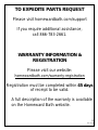
If parts are needed, please visit the “Support”
tab at www.homewardbath.com

1
Rev. 8.2018
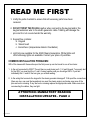
READ ME FIRST
1. Verify the parts checklist to ensure that all necessary parts have been
received.
2. DO NOT TWIST THE PLUGS together when connecting the keypad and/or the
keypad extension wire to the steam generator cable. Twisting will damage the
pins and it is not covered under the warranty.
3. Keypad box contains:
a. Keypad
b. Steam head
c. Escutcheon (temperature detector foundation)
4. Light kits are available for the GS08 Steam Generators. White lights and
chromotherapy lights are available. Contact your place of purchase.
COMMON INSTALLATION PROBLEMS:
99% of the issues with these units upon the first power up can be traced to one of two items:
1. Is the unit connected to 220V? The unit has no neutral wire just L1, L2 and Ground. To properly test
for the 220V you must test the L1 and L2 wires together and you should get 220V. If you test
individually the L1 and L2 that can give you a false reading.
2. Is the wiring that connects the keypad to the steam generator damaged? Pull apart the connections
(there are two, one near the keypad and one near the steam engine) and make sure none of the
pins are bent or missing. If any are bent or missing replace the appropriate cable. Make sure when
reconnecting the cables, they are tight.
ATTENTION: MANDATORY READING
INSTALLATION UPDATES - PAGE 4

2
Rev. 8.2018
WARNING!
To reduce the risk of injury, do not permit children to use this product unless they are closely supervised at all times.
WARNING!
To reduce the risk of injury:
a. The wet surfaces of steam enclosures may be slippery. Use care when entering or leaving.
b. The steam head is hot. Do not touch the steam head and avoid the steam near the steam head.
c. Prolonged use of the steam system can raise excessively the internal human body temperature and impair
the body’s ability to regulate its internal temperature (hyperthermia).
WARNING!
Hyperthermia occurs when the internal temperature of the body reaches a level several degrees above the normal
body temperature of 98.6° F. The symptoms of hyperthermia include an increase in the internal temperature of the
body, dizziness, lethargy, drowsiness, and fainting. The effects of hyperthermia include:
a) Failure to perceive heat;
b) Failure to recognize the need to exit the steam bath;
c) Unawareness of impending risk;
d) Fetal damage in pregnant women;
e) Physical inability to exit the steam bath; and
f) Unconsciousness.
WARNING!
The use of alcohol, drugs, or medication can greatly increase the risk of hyperthermia.
Limit your use of steam to 10 – 15 minutes until you are certain of your body’s reaction.
Excessive temperatures have a high potential for causing fetal damage during the early months of pregnancy.
Pregnant or possibly pregnant women should consult a physician regarding correct exposure.
Caution: Do not place wiring in close proximity to hot water or steam pipes.
Attention: If the installation and operation instruction are not read or understood, do not install. Install the controller
based on the installation instruction.
If the controller is installed outside the steam room, the temperature sensor must be installed in the steam room. To
prevent overheating, operate the controller as described in this manual only.
**Not for Space Heating Purposes

3
Rev. 8.2018
DANGER!
Afin de réduire les risque de blessures, ne jamais autoriser des enfants à utiliser ce appariel, sauf s’ils sont étroitement surveillés, à
tout moment
DANGER!
a) Les cabines où de la vapeur est introduite peuvent comporter des surfaces humides et donc glissantes. La plus grande
prudence est de rigueur au moment où l’utilisateur pénêtre, ou quitte la cabine
b) La tête d’injection de la vapeur est à haute temperature; il faut veiller à ne pas entrer en contact avec cette tête
d’injection. De plus, il faudra éviter le contact avec le jet de vapeur à proximité de la tête d’injection.
c) Soumis, d’une maniére prolongée aux températures occasionnées par un jet de vapeur, la température interne du corps
humain est susceptible de dépasser le seuil où celui-ci s’auto-régule, provoquant l’hyperthermie.
DANGER!
Le corps humain enter en hyperthermie quand sa température interne dépasse de plusieurs degrés sa temperature normale de 98.6º
Fahrenheit, soit 37°Celsius.
La personne en état d’ hyperthermie souffre d’étourdissements, est léthargique, assoupie et susceptible d’évanouissement.
Les effets de l’hyperthermie comportent:
a) Insensibilation à la chaleur
b) L’absence de volonté de quitter le local sous temperature élevée
c) Inconscience du danger imminent
d) En ce qui concerne les femmes enceintes, la possibilté de réactions nocives au niveau du fétus. Les femmes enceintes,
ou potentiellement enceintes, doivent préalablement consulter un médecin
e) Engourdissement physique menant à l’incapacité de quitter le local
f) Perte de connaissance
DANGER!
L’usage de drogues, d’alcool, de médicamments est susceptible d’augmentrer les risques d’hyperthermie dans de larges
proportions.
Avant utilization, il y a lieu de limiter votre usage de la vapeur à 10-15 minutes pour tester les réactions de votre corps.
Pendant les premiers mois de grosses, des températures excessives sont susceptibles d'engendrer des dommages, à issue fatale,
au fétus. Les personnes enceintes, ou probablement enceintes, doivent obtenir un avis médical en ce qui concerne les
conditions auxquelles elles peuvent se soumettre.
Avertissements
• Ne pas installer de fils à proximité d’eau chaude ou de conduits de vapeur
• La tête d’injection de vapeur ainsi que l’orifice de débit de vapeur sont à hautes températures – Eviter le contact de ces appareils
sous peine de brulûres.
• Cet appareil ne doit pas être utilisé à de fins de chauffage ambiant
• Avant toutes opérations de maintenance et de nettoyage, déconnecter la source de courant
Installation
• Installer la tête d’injection de vapeur enter 15 et 30 cm au-dessus du sol. Si le bain de vapeur se trouve dans la baignoire ou la salle
de bains, installer la tête d’injection de vapeur à 15 cm au-dessus de la baignoire
Le jet de vapeur doit être dirigé vers le bas. Entourer le filet du tuyau de vapeur de quelques couches de Teflon, visser la tête
d’injection de vapeur et visser manuellement.

4
Rev. 8.2018
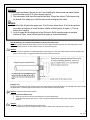
MANDATORY READING
INSTALLATION UPDATE BULLETIN
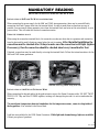
INSTALLATION OF 9KW AND 12 KW STEAM GENERATORS
When connecting the power supply for the 9kW and 12kW steam generators, there may be some difficulty
connecting the 8 and 6-gauge wires into the terminal block. In order to make these connections as easy as
possible, you can remove steam generator wires from the terminal block and wire nut the wires directly to your
power source. This will make the electrical connections easier.
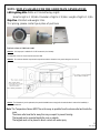
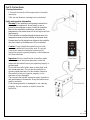
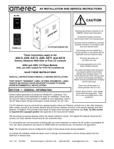
USING THE TERMINAL BLOCK
When using the connection terminal block, the connection can become loose due to expansion and contraction
from the heat and the small vibrations caused when the unit is running. After the initial installation the
connection must be checked after 30 days to make sure the connection is still tight (tighten
if necessary), then the connection should be checked about every 6 months after that.
If desired, connections may be made directly not using the terminal block. Follow the instructions above for the
9kW and 12kW steam generators.
Terminal block connected Terminal block by-passed using wire nuts
INSTALLATION OF THE KEYPAD EXTENSION WIRE
When connecting the keypad and/or the keypad extension wire to the Steam Generator cable, DO NOT TWIST
THE PLUGS. They are to be PUSHED together, twisting will damage the pins and it is not covered under the
warranty.
The escutcheon (temperature detector foundation) for the temperature sensor, comes in a bag inside of
the keypad box. Also included is the Steam Head.
Light kits are available for the GS08 Steam Generators. White light and chromotherapy lights are available.
Contact your place of purchase.

5
Rev. 8.2018
Part 1: Steam Generator
USER INSTRUCTIONS
Attention: We are not responsible for the malfunction and damage from improper installation that does not comply with the user’s manual.
1. Make sure the model and the accessories are correct, including the voltage 220V input.
2. Make sure the steam power is matched with the dimensions of the steam room. Pay attention to the steam room's cubic feet measurements
and construction materials. See below on how to choose your type of machine.
3. Make sure to read this manual carefully for correct and effective use.
4. We shall not be responsible for the product damage or malfunction caused by self-installation or the operation procedures which is not in
compliance with the Operation and Instruction Manual.
5. Please check the contents when the package arrives to ensure it is in good condition. If you find any damage in the package, please contact
the transportation company or the supplier to claim any damage.
6. This product must be used indoors.
CHOOSE YOUR TYPE OF MACHINE
Measure the length, width, and height in feet of the current steam shower or bathtub room.
Example; L:7 x W:5 x H:8 = 280 Cubic feet x 2 to get complete cubic measurement
Note: Multiplying the cubic feet by two is done to account for heat loss due to the room having natural stone such as
granite or marble, exterior walls, ceiling height exceeding 8 feet, ceramic tile, or glass walls.
6kW: Heats rooms 140-320 cubic feet
9kW: Heats rooms 320-460 cubic feet
12kW: Heats rooms 460-700 cubic feet
MAINTENANCE
Perform water discharge operation after each use. The unit will drain automatically 20 minutes after use.
1. Wait for the completion of automatic water discharge after each use of the steam engine to make sure the water in the
tank is discharged completely before cutting off power supply.
2. There should not be any leaking or damage to the steam engine, steam nozzle, components and pipes. They should
be checked monthly.
3. Clean the water supply pipes of the steam engine once a year.
4. Check all the connections, water, and electric to see if they have become loose or are damaged due to overheating.
5. Check the calcium build up in the water tank and on heating element. If the scale is thick, clean it (use diluted citric
acid to soak for 15-30 minutes).
6. Remove the water level sensor needle four times per year to clean the scale off the needle.
STEAM GENERATOR CLEANING
MAKE SURE POWER IS OFF
IF you can observe that the steam generator is draining after use, this means the tank is not clogged with debris or other
material from use. The tank cleaning procedure is not too difficult.
You have to introduce the citric acid solution in to the tank. 6 and 9kW units have a 1.5-gal tank, the 12kW has a 3.2-gal
tank. This can be done by disconnecting the steam line and with a funnel and hose pour the solution into the tank. If the
steam line cannot be disconnected you can unscrew the pressure relief valve and pour the solution in through the opening.
Both openings go the tank. Fill the tank until the solution starts to come out the steam outlet or the pressure relief valve
opening. Replace the steam line or the pressure relief valve, then turn on the steam generator on and let it produce steam
for about one minute, then shut it off at the circuit breaker and let sit for an hour or two. Then restart the generator and let it
run for about 5 minutes and shut it off at the key pad and wait until the automatic drain allows the solution to exit the tank
or use the manual drain button on the key pad. Once again it is most important you are able to actually verify the solution
has been drained out from the unit. By verifying the draining of the solution, you know the tank is not clogged. If the tank is
clogged it leads to premature heating element failure and other issues. This procedure will also clean the water level
sensor probe.
If the tank is not draining please call 1-866-783-2661 or 216-587-6790 for assistance

6
Rev. 8.2018
SENSOR PROBE REMOVAL FOR DIRECT CLEANING
Make sure the power is shut off at the circuit breaker. The water level sensor probe is located on top of the steam
generator tank. You need to remove the cover of the steam generator, next locate the large transformer, near it should be
a hole with three wires going into it and attached to tabs. That is the water level sensor. Older units have a ceramic sensor.
The newer units have a two-piece sensor, a nylon threaded ring and a red rubber center. The electrical connections are
the same, the sensor removal is slightly different. Note the color of the attached wires and the polarity of the tab they are
attached to. Unplug the wires and unscrew the sensor. The newer two-piece sensor requires you to unscrew the ring then
pull the red plug up to expose the sensor probes. Make sure there is no scale or debris on any of the three probes.
Reverse the above procedure to reinstall the sensor.
If needed the probe connections are as follows
Red wire connects to the shortest probe and is the positive wire ( + )
Yellow wire connects to the middle length probe and is the negative wire ( - )
Black wire connects to the longest probe and is the Ground wire.
CHOOSING PROPER LOCATION
Recommended locations for proper installation:
1. The steam box should not be located further than 16 feet away from the steam room.
2. The steam generator should not be installed in the steam room.
3. The steam generator should not be installed outdoors or in any place that will influence the security of the machine.
4. Do not install in any place where the water might freeze.
5. Do not install near flammable objects or chemicals (coal, gas, etc.)
6. The steam generator should be installed in a dry and ventilated place.
7. Make sure the steam generator is secured on the wall and is horizontally positioned.
8. On the other three sides, there has to be at least 6 inches of space left between steam generator and any other object.
9. The place where the machine is installed must be accessible for cleaning and possible service work.
10. The steam generator should be in close proximity to a drain for convenient Water Drain Valve hook-up.
11. After use, the steam pipe, safety valve, drain valve, water pipe, steam outlet is still very hot.
12. Place steam outlet away from bathers.
Attention: install an exhaust fan outside of the steam room so that it can expel any excess steam for proper ventilation.
13. The shorter and straighter the steam lines, the more efficient they will be.
14. The unit should be slightly higher than the steam outlet to allow condensation to drain out of the steam head.
15. Avoid using 90-degree fitting. Use 45-degree bends to allow better steam flow.
16. The steam line must be insulated.

7
Rev. 8.2018
Attention: The steam generator (including the controller) is ETL approved.
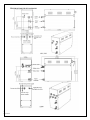
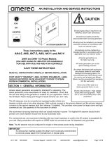
INSTALLATION DRAWING OF THE STEAM GENERATOR
INSTALLATION OF STEAM LINE
Attention: The installation of all the pipes should be completed by qualified plumbers or technicians.
1. Use brass or copper pipes only.
2. Do not use black, galvanized or PVC pipes for steam line.
Water supply pipe (1/2'') PVC or PEX is adequate
1. Connect cold water pipe to water inlet.
2. Install shutoff valve in the water supply pipe. The shutoff valve should be installed in a place where it is easily operated in case of
emergency.
3. Clean the water supply line completely before connecting it to the steam engine.
4. It is suggested that a water filter should be installed in the water supply pipe.
5. The water pressure should be no less than 20 pounds/square inch (psi), and no more than 75 (psi). If necessary, decrease or
increase the pressure accordingly. Higher water pressure can cause banging when filling with water.
Steam line must be 3/4''
1. Do not install any valves in the steam line. The steam line can never be obstructed.
2. Install a brass or copper steam line (size 3/4'') between the steam outlet and the steam nozzle.
3. The insulation material used to insulate the steam pipe should be resistant to temperature as high as 248º F or higher.
4. Do not bend the pipe so that the water will stay in the curve of the steam line.
5. The shorter the steam line, the better. Try to decrease the number of elbows and avoid abrupt turns. Use 45-degree bends instead
of 90-degree T.
6. Have no valleys or dips in the output steam line.
7. Do not connect the drain valve into the steam line.
8. Do not connect the pressure release valve into the steam line.
9. Make sure the steam line is well insulated.
Steam nozzle is 3/4''
S team g enerato r
Water D rain Valv e
Water Inlet P ipe
S team
outlet
pip e
C on tr ol p an el
S u p ply
S team O u tlet
P res s ure relief v alv e
!
A t t en t io n :
T h e d r a w i n g i s o n l y
f o r e x p la n a t io n .
F o r p r a c tic a l d e s ig n o f s te a m
r o o m , p l e a s e c o n s u l t w i t h
q u a l i fi e d d e s ig n e r, a r c h i te c t
o r b u il d e r.

8
Rev. 8.2018
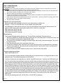
Note: Aromatherapy oils are placed in the indentation at the top of the steam nozzle.
Attention: In order to protect the steam nozzle, do not use any tools to tighten that will scratch finish, use a little soapy water and soft
sponge to wipe, and do not use corrosive chemical solutions or abrasive cleaning tools.
Attention:
Please consult your distributors of building materials like acrylic, fiberglass or other heat-resistant material around the installation and
position of steam nozzle. It is suggested that MS-103412 heat resistant material is used.
Drainpipe (1/2'')
According to national and local codes, the steam engine drain valve should be equipped with drainpipe. The drainpipe must be able to handle
200-degree water. The steam engine will drain water on its own after 20 minutes. It is a gravity drain.
Attention: drainpipe should not incline upwards.
Safety valve (Pressure Release Valve)
1. Safety valve is to prevent too much steam pressure in the interior steam engine.
2. The pressure limit range of safety valve is 10 PSI. If the pressure should become too high over this value, the valve will release the
pressure.
Attention:
1. For safety, do not dismantle the pressure release valve.
2. To maintain the proper and automatic operation of pressure release valve, make sure the connection is tight.
WARNING!
The steam nozzle and steam outlet are very hot! Avoid installing the steam nozzle near steam bathers.
1. Install the steam nozzle 6-12 inches above the ground.
2. The steam spray outlet should be installed face down. Wrap a few circles of Teflon tape around
the threads of the steam pipe, install the steam nozzle and tighten with hands.
DANGER!
1. Installer la tête d’injection de vapeur enter 15 et 30 cm au-dessus du sol. Si le bain de vapeur se
trouve dans la baignoire ou la salle de bains, installer la tête d’injection de vapeur à 15 cm au-
dessus de la baignoire
2. Le jet de vapeur doit être dirigé vers le bas. Entourer le filet du tuyau de vapeur de quelques
couches de Teflon, visser la tête d’injection de vapeur et visser manuellement

9
Rev. 8.2018
BLUEPRINT FOR THE STEAM ENGINE

10
Rev. 8.2018
Attention: Keep the steam engine clean.
Attention: To avoid damage to the equipment, do not connect power directly to the components.
IMPORTANT: Each unit is provided with a pressure-release device (safety valve) to address overpressure due to inadvertent blockage of the
output steam head or piping.
ELECTRICAL REQUIREMENTS:
Electricity supply circuitry:
1. Test the voltage of the electric supply and make sure that the steam engine is supplied with suitable electric power.
2. Insulated copper wire should be used with a heat-resistant temperature of 190ºF and a specified voltage of 500V. Refer to national
or local electricity code for the specifications. Refer to the ammeter for the ampere.
3. Make sure the steam engine and power supply are appropriate for each other.
4. Install an independent GFCI circuit breaker between the power supply and the steam engine.
Important: All the connections must be in accordance with national and local electricity code and be installed by professional electricians.
Note: All units are 220-240 Volts. The terminal may read N, L, G. The N is not a neutral. It is the second leg of the 220V of the power source.
AMPERE METER
Type
Applicable
space of
room (ft
3
)
Electricity supply
Electrical current
draw (Amps)
Specifications for
for power wire ( A W G)
GS08-6Kw
140-320
220-240V / (1PH/2PH)
27.3A (30 Amps)
#10 or 6mm
GS08-9kW
320-460
220-240V / (1PH/2PH)
41A (50 Amps)
#8 or 8mm
GS08-12kW
460-700
220-240V / (1PH/2PH)
55A (60 Amps)
#6 or 10mm
ASSEMBLY GRAPH FOR POWER WIRE
Attention: To avoid the damage to the equipment, do not connect power directly to components.
WARNING!
This graph is for explanation only. For actual installation, refer to national and local electric codes and consult with a professional electrician.
See Installation Update Bulletin on Page 4.

11
Rev. 8.2018
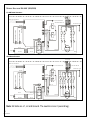
WIRING DIAGRAM 220-240V (1PH/2PH)
6 & 9kW Steam Generators:
12kW Steam Generator:
Note: All Units are L1, L2 and Ground. The neutral is Line 2 (second leg).
G S 08-3kW (220-240V ~ 1P H /2P H )
G S 08-6kW /7.5k W /9kW (220-240V ~ 1P H /2P H )
G S 08-4.5kW (220-240V ~ 1P H /2P H )
J2-1
J2-2
J1-2
J1-1
J1
J2
S S
S u p p l y
Red
Black
R e d
B la c k
Re d
R ed
T o C on tro l P a na l
Fill water valve
Drain water valve
Te rm ina l B lo c k
Ye llow /G re e n
R e d
B la c k
R ed
Black
Yellow
R e d
B l ack
Red
Red
Red
Re d
Water Level Senso r
R e d ( S h o r t P i n )
B l a c k ( L o n g P i n )
Y e l l o w ( M i d d l e P i n )
Re d
Black
R e d
B l u e
B ro w n R e d
L ig h t
J1-1
J1-2
J1
S S
L1
G
S u p p l y
Red
R e d
B l a c k
T o C o n t ro l P a n a l
Fill water valve
Drain water valve
T e rm i n a l B l o c k
Y e l l o w / G re e n
R e d
B l a c k
R e d
Black
Yellow
R e d
B l ack
Red
Red
Red
Red
W ate r L e v e l S e n so r
R e d ( S h o r t P i n )
B l a c k ( L o n g P i n )
Y e l l o w ( M i d d l e P i n )
Black
R e d
B l u e
B ro w n R e d
L ig h t
J1-1
J1-2
J1
S S
S u p p l y
Red
R e d
B l a c k
T o C o n t ro l P a n a l
Fill water valve
Drain water valve
T e rm i n a l B l o c k
Y e l l o w / G re e n
R e d
B l a c k
R e d
Black
Yellow
R e d
B l ack
Red
Red
Red
Red
W ate r L e v e l S e n so r
R e d ( S h o r t P i n )
B l a c k ( L o n g P i n )
Y e l l o w ( M i d d l e P i n )
Black
R e d
B l u e
B ro w n R e d
L ig h t
L2
Black
Black
N L
L1
G
L2
N L
L1
G
L2
N L
G S 08- 0V ~ 1P H /2P H )10.5kW /12kW (220-24
J1-1
J3-2
J2-2
J1-2
J1
S S
Red
Black
R e d
B l a c k
Red
Red
T o C o n t ro l P a n a l
Fill water valve
Drain water valve
T e rm i n a l B l o c k
Y e l l o w / G r e e n
R e d
B l a c k
R e d
Black
Yellow
R e d
B l a c k
Red
Red
Red
Red
W a ter L e v e l Sen so r
R e d ( S h o r t P i n )
B l a c k ( L o n g P i n )
Y e l l o w ( M i d d l e P i n )
Red
Black
R e d
B l u e
B ro w n R e d
L ig h t
Red
Red
S u p p l y
J2
J3
J2-1
Black
J3-1
Black
Black
Black
L1
G
L2
N L

12
Rev. 8.2018
NOTE: NOW AVAILABLE FOR THE GS08 STEAM GENERATORS
LED Lighting Kits -White or Chromotherapy Lights
Hole for light is 1 13/16in. Diameter of light is 2 3/16in. Length of light is 1 1/2in
Drip Pan- 20x10x1 and weighs 3 lbs.
*For pricing, please contact your place of purchase
INSTALLATION OF THE TOP LIGHT
Attention: 12V output port is available for 12V DC accessories (not included).
The total draw on the 12V circuit cannot be more than 35W
Attention: Do not let the electrical components be exposed to moisture; otherwise, it may cause damage or short circuit.
Caution: The illustration is just for explanation; the practical installation must comply with the national electric code and be installed by a
professional electrician.
Note: The Temperature Sensor MUST be as far away as possible from the steam outlet and inside the
room.
The steam outlet must be far away from any occupant to prevent burning.
The keypad can be mounted inside the room or outside.
The keypad must not be placed in direct contact with water spray.

13
Rev. 8.2018
1
2
3
4
6
5
7
9
8
1
Enclosure
2
Insulation bracket
3
Circuit board
4
Steam Outlet
5
Pressure relief valve
6
Water fill valve
7
Water drain valve
8
Subsidiary water tank
9
Main water tank
Heating Element
221 F Hi-limit
O
Transformer
Terminal block
Fuse
Ground connector
Relay
Water level sensor
221 F Hi-limit
O
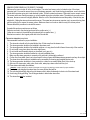
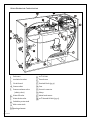
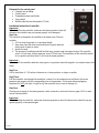
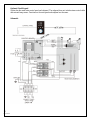
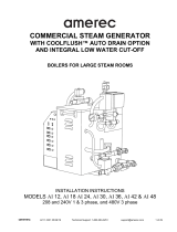
STEAM GENERATOR CONFIGURATION
Enclosure
Insulation bracket
Circuit board
Steam outlet
Pressure release valve
(safety valve)
Water fill valve
Water drain valve
Subsidiary water tank
Main water tank
Heating element
221°F Hi-limit
Transformer
Terminal block (pg 4)
Fuse
Ground connector
Relays
Water level sensor
221°F Manual Hi-limit (pg 15)

14
Rev. 8.2018
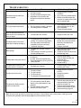
TROUBLE SHOOTING:
Trouble
Causes of Trouble
Trouble-Shooting Method
The machine does not start when
power is supplied
1. The fuse is burned
2. The wire connection terminal is loose
3. Bad contact in the connection wire
between the controller and the steam
engine
1. Change the fuse (on the shell
0.8A/250V)
2. Plug-in the wire connection terminal
3. Make sure the steam engine and
controller are in good contact. Check
pins on controller cable
GFCI switch breaks automatically
1. The wire connector is damp or damaged
2. The heating element is damaged
1. Check whether the wire connector is
damp or damaged, and dry with
dryer if dampened
2. Change the heating element
When the machine is started, hot
water comes out from the drain with
little or no steam
1. The water drain valve is broken
1. Change the water drain valve
The display screen on the control
panel does not display (see page 1)
1. The power wire is not connected
properly. The connection plug between
the control panel and the electrically-
controlled box is loose (check pins)
2. Trouble with plug board
1. Check whether the connection plug
between the control panel and the
electrically-controlled box has
become loose
2. Change a plug board
Water leakage
1. The water pipe connector is loose or
broken
2. Water leakage in the water input valve or
the water drainage valve
1. Tighten the loose connector and/or
change the broken pipe
2. Change the water input valve or the
water drainage valve
No steam when starting the machine
1. No electricity
2. No water, red light of keypad blinking
3. The set temperature is too low (over 120º)
4. Trouble with wire
1. Check the power supply
2. Check the water input pipe and
water input valve
3. Reset the temperature
4. Contact the MFG
The steam does not come out, there
are water sounds in the machine
1. The steam pipe is jammed
1. Cut power supply to check whether
the steam pipe is clean
The light cannot be turned on
1. The fuse is burned
2. The light is broken
3. The wire is broken
4. The plug does not have good contact
1. Change the fuse (on the shell
1A/250V)
2. Change the light bulb
3. Change wire
4. Replace plug
The display box displays normally,
but with no steam output
1. Too much pressure inside the steam
engine, so the system breaks for heat
protection
2. The heat protection wire is broken
3. Manual hi-limit switch tripped
1. Check the team transport pipe and
restore automatically after heat
protection becomes cool
2. Check the heat protection wire to
make sure the connection is good
3. See manual hi-limit (page 15)
Note: The main control cable has 13 pins that control everything. If the unit doesn’t work or work properly, check the pins and
connections at the generator and at the keypad. Make sure all connections are intact.

15
Rev. 8.2018
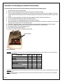
Instructions for Resetting the manual hi-limit switches
If the unit fills with water but does not produce steam, the issue may not be the heating element.
1. Shut off the power to the unit at the breaker.
2. Remove the top of the steam generator and make sure the power connections are tight.
3. There is an update that allows you to disconnect the wires from the terminal block and wire nut them together. This will not
void the warranty and eliminates the need for checking the tightness of the electrical connections as stated on page 4 of the
manual.
4. If power connections are tight go to the side of the steam generator where the electrical connections are.
5. You will see a plate that is held on by 4/6 screws, remove that plate.
6. You will have direct view of the heating elements and the power connections.
7. Above each element is a small black plastic square. In the center of that square is a reset button, push each one if you hear a
click that was your problem. This is a hi-limit heat protector.
8. If that does not solve the problem, unscrew the bottom wire from each element. The elements are mounted vertically.
9. If you have a voltage tester set it to tone, touch the top element terminal with the terminal below it.
10. You should get a buzz, if you do the element is good.
11. Do the same thing for the second element.
12. If there is no sound the element is bad and needs replacing.
SPECIFICATIONS
Important: The list below is for reference only. In actual checking and repairing based on the national and local codes, ask professional
service personnel for advice.
Power Output
6kW
9kW
12kW
Potency Error
±10%
±10%
±10%
Duration
>1500V
>1500V
>1500V
Resistance
>20W
>20W
>20W
Steam Pressure
0.14MPa
0.14MPa
0.16MPa
Steam Volume
180
260
360
Steam Production Time
4-8 mins
4-8 mins
4-8 mins
Water Tank Volume
1.5GAL
1.5GAL
3.2GAL
Applicable space of the room (ft
3
)
140-320
320-460
460-700
Important: The parameter listed in the above table may vary from place and temperature, please consult a qualified designer or architect for
more detailed use.
NOTE: Steam Bath Generators are considered to be able to operate above atmospheric pressure in normal operation and shall therefore
comply with UL clause 64.8.
Reset Buttons

16
Rev. 8.2018
PART 2: CONTROL PANEL
Cleaning Instructions
1.Use soft cloth with a little soap water to clean the
controller.
2.Do not use abrasive cleaning tools or material.
Safety and operation information
Warning: If the installation and operation instructions
are not read or understood, do not install or use, to
prevent serious damage or injury. Install the controller
based on the installation instructions, otherwise, the
temperature in the steam room will be too high or will not
heat properly.
If the controller is installed outside the steam room, the
temperature sensor must be installed in the steam room.
Operate based on the instructions otherwise the controller
may lose control or the bathroom will be overheated.
Caution: Do not install the controller wire in the
same wire rabbet with any other wire. Do not get
close to hot water or steam pipe otherwise the
controller may not operate properly or the bathroom
will be overheated.
Important: Before installing the controller, make
sure the power to the steam generator is shut off
otherwise the controller may not operate properly or
get damaged.
Do not use controller other than as described with
this steam generator. Do not use the controller to
operate steam generator of other brands otherwise
the controller may not operate properly or the
machine will get damaged.
The instructions include important safety, operation
and maintenance information. Keep the instructions
readily available.
If the steam generator is damaged or not running
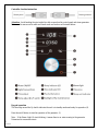
properly, do not continue to install or use the
controller.

17
Rev. 8.2018
Blueprint for the control panel
• Complete set including:
• Control panel
• Temperature sensor and holder
• User manual
• Middle cable between dual panels (6.5 feet)
Installation instruction of controller
Important
Before installing the controller, make sure the steam generator is shut off
otherwise the controller may not operate properly or be damaged.
Step One:
The controller is designed to be installed in the steam room. Points to
consider:
1. 4-5 feet from the ground or a convenient height.
2. Keep away from the steam nozzle and do not expose under the
direct spray of steam or water.
3. Install on a wall.
4. The position of installation should facilitate easy operation and convenient wiring. The controller
wire is 1.6 feet long, with an extension wire of 20 feet long. The installation of the controller should
be in a position not more than 21 feet from the steam generator.
Important
Do not install the controller under the water pipe or in a position where the keypad is in constant contact with
water.
Step Two:
Drill a round hole of 1 3/8 inches in diameter in a chosen position, no larger or smaller.
Step Three:
Pull the controller wire through the round hole, connect it to the extension wire and then to the steam
generator and connect with the corresponding wire in the generator. Do the same when unplugging.
Important Do NOT pull tight, fix tight or clip the controller wire in case of damage to it.
Step Four:
Start the power supply to the steam generator, check connection, check each item on pages 18-19 to make
sure all functions work.
Important
Before attaching the controller, make sure the steam generator is shut off otherwise the controller may not
operate properly or become damaged.

18
Rev. 8.2018
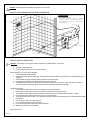
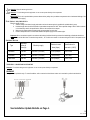
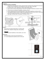
Step Five:
Temperature detector installation
1. The position of the temperature detector should be about head high while sitting and as far away as
possible from the steam head. Avoid installing near the steam outlet or room door.
2. As shown in Fig. 1, drill a small hole of 3/8in. in the selected position.
3. Apply a circle of silicone along the edge of the back of the detector foundation (as shown in Fig 2)
4. Use a lock nut to lock detector foundation. (as shown in Fig .2)
5. Let the temperature detector go through the back of the detector foundation (as shown in Fig. 3)
6. The temperature detector should be installed by extending about 3/8 in from the front of the room to
make sure the speed and accuracy of the temperature control is correct.
7. Apply glue to the back and fix the detector. (as shown in Fig. 3)
Step Six:
Remove the cover paper at the bottom. To achieve good
adhesion effect, keep the sticking surface clean and dry.
Important
To ensure horizontal installation of the controller, use a level.
Step Seven:
Locate the display screen in the vertical direction of
12 o’clock and press the controller to stick it to the wall.
La page est en cours de chargement...
La page est en cours de chargement...
La page est en cours de chargement...
La page est en cours de chargement...
La page est en cours de chargement...
-
 1
1
-
 2
2
-
 3
3
-
 4
4
-
 5
5
-
 6
6
-
 7
7
-
 8
8
-
 9
9
-
 10
10
-
 11
11
-
 12
12
-
 13
13
-
 14
14
-
 15
15
-
 16
16
-
 17
17
-
 18
18
-
 19
19
-
 20
20
-
 21
21
-
 22
22
-
 23
23
-
 24
24
-
 25
25


dans d''autres langues
Autres documents
-
Ariel DZ938F8 Guide d'installation
-
 Amerec EasySteam Generator "AK4.5", "AK7.5", "AK11" & "AK14" Mode d'emploi
-
 Amerec EasySteam Generator-Canada Only "AK4.5", "AK7.5", "AK11" & "AK14" Mode d'emploi
-
Kohler 5535-NA Guide d'installation
-
Kohler K-5526-NA Guide d'installation
-
Blodgett BC-20G Manuel utilisateur
-
-
 Amerec AX Generator, "AX4.5", "AX6", "AX7.5", "AX9", "AX11" & "AX14" Mode d'emploi
-
 Amerec AK Generator, "AK4.5", "AK6", "AK7.5", "AK9", "AK11" & "AK14" Mode d'emploi
-
 Amerec AI Boiler, "AI12 Through AI48" Mode d'emploi


