Kichler Lighting 42044OZWH Manuel utilisateur
- Taper
- Manuel utilisateur

Connect Black or
Red Supply Wire to:
Connect
White Supply Wire to:
Black White
*Parallel cord (round & smooth) *Parallel cord (square & ridged)
Clear, Brown, Gold or Black
without tracer
Clear, Brown, Gold or Black
with tracer
Insulated wire (other than green)
with copper conductor
Insulated wire (other than green)
with silver conductor
*Note: When parallel wires (SPT I & SPT II)
are used. The neutral wire is square shaped
or ridged and the other wire will be round in
shape or smooth (see illus.)
Neutral Wire
Connecter le fil noir ou
rouge de la boite
Connecter le l blanc de la boîte
A NoirA Blanc
*Au cordon parallèle (rond et lisse)
*Au cordon parallele (à angles droits el strié)
Au bransparent, doré, marron, ou
noir sans l distinctif
Au transparent, doré, marron, ou
noir avec un til distinctif
Fil isolé (sauf l vert) avec
conducteur en cuivre
Fil isolé (sauf l vert) avec
conducteur en argent
*Remarque: Avec emploi d’un fil paralléle
(SPT I et SPT II). Le l neutre est á angles
dr oits ou strié et l’autre l doit étre rond ou
lisse (Voir le schéma).
Fil Neutre
9) Connecterlesls.Sereporterautableaucidessouspourfairelescon
nexions.
10)Pousserleluminaireversleplafondenpassantsoigneusementlesvis
demontageparlestrousdanslecache.
11) Fixerleluminaireauplafondàl’aidedesboutonsmoletés.
12)Insérezlarondelleenplastiqueendessousdelarondelledemétalsur
duluminaire.
13)Souleverleverrejusqu’auluminaire.Passerlepetittrouenhautdu
verresurladouille.
14)Unefoisqueleverreestsoulevésurlecoupleurfendu,insérerla
rondelletransparenteetlarondelleenacierdanslafenteducoupleur
fendu(voirillustration).
15)Abaisserleverresurlarondelletransparenteetlarondelleenacier.
CAUTION – RISK OF SHOCK – Disconnect Power at the main circuit
breaker panel or main fuse box before starting and during the installa-
tion.
WARNING:
This xture is intended for installation in accordance with the National
Electrical Code (NEC) and all local code specications. If you are not
familiar with code requirements, installation by a certied electrician is
recommended.
NOTE direction of swivel in accordance with ceiling.
1) Slipcapupoverendofbottomstem.
2) Threadthatendofbottomstemontotopofxturebody.
3) Passxturewirethroughremainingstemsandscrewstemstogether.
NOTE: Threadlockingcompoundmustbeappliedtoallstemthreads
asnotedwithsymbol(3)topreventaccidentalrotationofxtureduring
cleaning,relamping,etc.
4) Threadswivelontoendoflaststem.
5) Passthreadedpipeonendofswivelupthroughholeincanopy.
6) Sliplockwasheroverendofthreadedpipeprotrudingfrominside
canopy.Threadhexnutontothreadedpipe.Tightenhexnuttosecure
swiveltocanopy.
7) Findtheappropriatethreadedholesonmountingstrap.Assemble
mountingscrewsintothreadedholes.
8) Attachmountingstraptooutletbox.Mountingstrapcanbeadjustedto
suitpositionofxture.
9) Makewireconnections.Referencechartbelowforcorrectconnections
andwireaccordingly.
10)Pushxturetoceiling,carefullypassingmountingscrewsthroughholes
incanopy.
11) Securexturetoceilingwithknurlknobs.
12)Insertplasticwasherbelowmetalwasheronxturebody.
13)Raiseglassuptowardsxture.Passsmallholeintopofglassover
socket.
14)Oncetheglassisraisedovertheslottedcoupler,inserttheclearwasher
andsteelwasherintotheslotoftheslottedcouplerasshown.
15)Lowerglassontotheclearwasherandsteelwasher.
ATTENTION – RISQUE DE DÉCHARGES ÉLECTRIQUES – Couper le
courant au niveau du panneau du disjoncteur du circuit principal ou
de la boîte à fusibles principale avant de procéder à l’installation.
ATTENTION:
Ce luminaire doit être installé conformément aux codes d’électricité
nationaux (NEC) et satisfaire toutes les spécications des codes
locaux. Si vous ne connaissez pas les exigences de ces codes, il est
recommandé de coner l’installation à un électricien certié.
Prenez note de la direction de la rotule conformément au plafond.
1) Glissezlecapuchonau-dessusduboutdelatigeenbas.
2) Visserl’extrémitédelatigeinférieuresurlapartiesupérieureducorps
duluminaire.
3)Acheminerlelduluminaireparlestigesetvisserlestigesensemble.
REMARQUE :appliquerlefreinletsurtouslesletsdelatige
indiquésparlesymbole(3)pourempêcherlarotationaccidentelle
duluminairependantlenettoyage,remplacementdelampe,etc.
4) Visserlarotulesurl’extrémitédelatigedernière.
5) Fairepasserletubeletésurl’extrémitédel’jusqu’àrotuledansletrou
ducache.
6) Passerlarondelledeblocagesurletubeletésortantdel’intérieurdu
cache.Visserl’écrouhexagonalsurletubeleté.Serrerl’écrouhexagonal
pourgarantirlarotuleàlacache.
7) Trouverlestrousletésappropriéssurlabarrettedemontage.Vissez
lesvisdemontagedanslestrousletés.
8) Visserlabarrettedemontageàlaboitedejonction.Labarrettede
montagepeutetreajustéepourconveniràlapositiondel’applique.
IS-42044-CB
I NSTRUCTIONS
For Assembling and Installing Fixtures in Canada
Pour L’assemblage et L’installation Au Canada
We’reheretohelp/Noussommeslàpourvousaider866-558-5706
Hrs:M-F9amto5pmEST/
Heures:dulundiauvendredi,de9hà17h(heuredel’Est)
Cauons
Installaon Instrucons
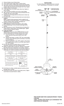
Fixture Diagram / Diagramme d’appareils
Précauons
Instrucons d’installaon
Instrucons d’installaon (suite)
MOUNTINGSTRAP
PATTEDEFIXATION
CANOPY
CACHE
STEM
TIGE
KNURLKNOB
BOUTONMOLETÉ
SWIVEL
ROTULE
4
3
3
3
GLASS
VERRE
FIXTUREBODY
LUMINAIRE
HEXNUT
ECROUHEXAGONAL
LOCKWASHER
RONDELLEDEBLOCAGE
CAP
CAPUCHON
PLASTICWASHER
RONDELLEENPLASTIQUE
METALWASHER
RONDELLEDE
MÉTAL
-
 1
1
Kichler Lighting 42044OZWH Manuel utilisateur
- Taper
- Manuel utilisateur
dans d''autres langues
Documents connexes
-
 Kichler Lighting 3482NI Manuel utilisateur
-
 Kichler Lighting 43189AUB Manuel utilisateur
-
 Kichler Lighting 43792NI Manuel utilisateur
-
 Kichler Lighting 43201OZ Manuel utilisateur
-
 Kichler Lighting 42475CHCLR Manuel utilisateur
-
 Kichler Lighting 43152AP Manuel utilisateur
-
 Kichler Lighting 42167OZWH Manuel utilisateur


