Kichler Lighting 49964AVI Manuel utilisateur
- Taper
- Manuel utilisateur

Date Issued: 09/12/17 IS-49964-CB
We’re here to help 866-558-5706
Hrs: M-F 9am to 5pm EST
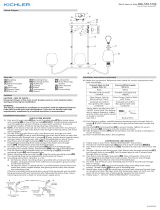
CAUTION – RISK OF SHOCK –
Disconnect Power at the main circuit breaker panel or main
fusebox before starting and during the installation.
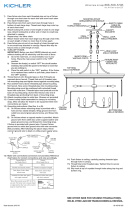
1) Thread small threaded pipe[1] into end of second loop[2]. Pass
threaded pipe on loop up through hole in canopy[3].
2) Thread lockwasher[4] onto end of threaded pipe protruding
from inside canopy.
3) Thread hexnut[5] onto threaded pipe protruding from inside
canopy.
4) Attach one end of chain[6] to loop[7] on top of roof. Attach
other end of chain to small loop on canopy.
5) Weave electrical wire and ground wire through chain links no
more than 3 inches apart.
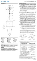
6) Find the appropriate threaded holes on mounting strap[8] that
align with hole distance in canopy. Thread mounting screws[9]
into threaded holes starting from outlet box[10] side.
7) Attach mounting strap to outlet box with strap mounting
screws[11]. Mounting strap can be adjusted to suit position of
xture.
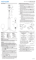
8) Grounding instructions: (See Illus. A or B).
A) Onxtureswheremountingstrapisprovidedwithahole
and two raised dimples. Wrap ground wire from outlet box
around green ground screw, and thread into hole.
B) Onxtureswhereacuppedwasherisprovided.Attach
ground wire from outlet box under cupped washer and
green ground screw, and thread into mounting strap.
Ifxtureisprovidedwithgroundwire.Connectxtureground
wire to outlet box ground wire with wire connector. After follow-
ing the above steps. Never con¬nect ground wire to black or
white power supply wires.
9) Make wire connections. Reference chart below for correct con-
nections and wire accordingly.
10) Pushxturetoceiling,carefullypassingmountingscrews
through holes in canopy.
11) Thread lock-up knobs[12] onto mounting screws. Tighten
knobstosecurexturetoceiling.
12) Raise glass[13]upintoxture,passthesmalleropeningofthe
glass over socket[14]. Rest the top of the glass against the
padsinthextureroof.
13) Thread the socket ring[15] onto the socket. Tighten to secure
the glass in place. (Do not over-tighten).
14 ) Insert recommended bulb (Not supplied).
GREEN GROUND
SCREW
CUPPED
WASHER
OUTLET BOX
GROUND
FIXTURE
GROUND
DIMPLES
WIRE CONNECTOR
OUTLET BOX
GROUND
GREEN GROUND
SCREW
FIXTURE
GROUND
A
B
Connect Black or
Red Supply Wire to:
Connect
White Supply Wire to:
Black White
*Parallel cord (round & smooth) *Parallel cord (square & ridged)
Clear, Brown, Gold or Black
without tracer
Clear, Brown, Gold or Black
with tracer
Insulated wire (other than green)
with copper conductor
Insulated wire (other than green)
with silver conductor
*Note: When parallel wires (SPT I & SPT II)
are used. The neutral wire is square shaped
or ridged and the other wire will be round in
shape or smooth (see illus.)
Neutral Wire
14
13
15
9
10
11
8
3
12
6
2
5
4
1
7

Date Issued: 09/12/17 IS-49964-CB
INSTRUCTIONS
For Assembling and Installing Fixtures in Canada
Pour L’assemblage et L’installation Au Canada
Nous sommes là pour vous aider 866-558-5706
Heures : du lundi au vendredi, de 9h à 17h (heure de l’Est)
ATTENTION – RISQUE DE DÉCHARGES ÉLECTRIQUES -
Couper le courant au niveau du panneau du disjoncteur du
circuit principal ou de la boîte à fusibles principale avant de
procéder à l’installation.
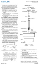
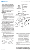
1) Visser le petit tube leté dans l’extrémité de la seconde bou-
cle[1][2] Passer le tube leté sur la boucle jusqu’à l’à travers le
trou dans le cache[3].
2) Visser une rondelle de blocage sur l’extrémité du tube leté
sortant du cache[4].
3) Visser un écrou hexagonal sur le tube leté sortant du
cache[5].
4) Fixer une extrémité de la chaîne à la boucle au-dessus du
luminaire[6][7]. Fixer l’autre extrémité de la chaîne à la boucle
sur le cache.
5) Passer le l électrique et le l de terre d’un maillon à l’autre de
la chaîne avec une distance maximale de 7,5 cm entre.
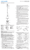
6) Trouvez les trous letés appropriés sur la sangle de montage
[8] qui s’alignent sur la distance du trou dans la verrière. En-
ler les vis de xation [9] dans les trous letés à partir du côté
sortie de la boîte [10].
7) Fixez la sangle de montage à la boîte de sortie avec les vis
de xation de la sangle [11]. La sangle de montage peut être
réglée en fonction de la position du luminaire.
8) Connecter les ls (connecteurs non fournis). Se reporter au
tableau ci-dessous pour faire les connexions.
9) Pousser le luminaire vers le plafond en passant soigneuse-
ment les vis de montage par les trous dans le cache.
10) Boutons de verrouillage de l [12] sur les vis de montage.
Serrez les boutons pour xer le luminaire au plafond.
11) Soulever le verre [13] dans le luminaire, passer l’ouverture
plus petite du verre sur la douille [14]. Reposez le dessus du
verre contre les tampons dans le toit de l’appareil.
12) Enler la douille [15] sur la prise. Serrer pour xer le verre en
place. (Ne pas trop serrer).
13) Insérez l’ampoule recommandée (non fournie).
Connecter le fil noir ou
rouge de la boite
Connecter le fil blanc de la boîte
A Noir A Blanc
*Au cordon parallèle (rond et lisse)
*Au cordon parallele (à angles droits el strié)
Au bransparent, doré, marron, ou
noir sans fil distinctif
Au transparent, doré, marron, ou
noir avec un til distinctif
Fil isolé (sauf fil vert) avec
conducteur en cuivre
Fil isolé (sauf fil vert) avec
conducteur en argent
*Remarque: Avec emploi d’un fil paralléle
(SPT I et SPT II). Le fil neutre est á angles
droits ou strié et l’autre fil doit étre rond ou
lisse (Voir le schéma).
Fil Neutre
14
13
15
9
10
11
8
3
12
6
2
5
4
1
7
-
 1
1
-
 2
2


Kichler Lighting 49964AVI Manuel utilisateur
- Taper
- Manuel utilisateur
dans d''autres langues
Documents connexes
-
 Kichler Lighting 49879BK Manuel utilisateur
-
 Kichler Lighting 44379BK Manuel utilisateur
-
 Kichler Lighting 49236BSL Manuel utilisateur
-
Kichler 43696BK Manuel utilisateur
-
 Kichler Lighting 43153AP Manuel utilisateur
-
 Kichler Lighting 43011NBR Manuel utilisateur
-
 Kichler Lighting 43745OZ Manuel utilisateur
-
 Kichler Lighting 44377BK Manuel utilisateur
-
 Kichler Lighting 43234OZ Manuel utilisateur


