Rockford Fosgate 575M265 M2-65 Manuel utilisateur
- Catégorie
- Accessoires de moto
- Taper
- Manuel utilisateur

M2-65
M2-65B
M2-8
M2-8B
M2-8H
M2-8HB
M2-10H
M2-10HB
M2-TS
Installation & Operation

2
2 Introduction
3 Specifications
4-7 Diagrams
8 Wiring
9-11 Installation Considerations
Mounting
12-23 Additional Languages
French
Spanish
German
Italian
24 Limited Warranty Information
PRACTICE SAFE SOUND
Continuous exposure to sound pressure levels over 100dB may
cause permanent hearing loss. High powered auto sound systems
may produce sound pressure levels well over 130dB. Use common
sense and practice safe sound.
PRATIQUEZ UNE ÉCOUTE SANS RISQUES
Une exposition continue à des niveaux de pression acoustique
upérieurs à 100 dB peut causer une perte d’acuité auditive
permanente. Les systèmes audio de forte puissance pour auto
peuvent produire des niveaux de pression acoustique bien au-delà
de 130 dB. Faites preuve de bon sens et pratiquez une écoute sans
risques
PRACTIQUE EL SONIDO SEGURO
El contacto continuo con niveles de presión de sonido superiores
a 100 dB puede causar la pérdida permanente de la audición. Los
sistemas de sonido de alta potencia para automóviles pueden
producir niveles de presión de sonido superiores a los 130 dB. Aplique
el sentido común y practique el sonido seguro.
PRAKTIZIEREN SIE SICHEREN SOUND
Fortgesetzte Geräuschdruckpegel von über 100 dB können beim
Menschen zu permanentem Hörverlust führen. Leistungsstarke
Autosoundsysteme können Geräuschdruckpegel erzeugen, die weit
über 130 dB liegen. Bitte wenden Sie gesunden Menschenverstand an
und praktizieren Sie sicheren Sound.
OSSERVATE LE REGOLE DEL SUONO SENZA PERICOLI
La costante esposizione a livelli di pressione acustica al di sopra dei
100dB possono causare la perdita permanente dell’udito. I sistemi
audio ad alta potenza possono produrre livelli di pressione acustica
ben superiori ai 130dB. Si consiglia il buon senso e l’osservanza delle
regole del suono senza pericoli
Introduction
Dear
Customer,
Congratulations
on
your
purchase
of the world's finest
brand
of
audio products.
At
Rockford
Fosgate
we
are
fanatics about musical
reproduction at its
best,
and
we
are
pleased
you
chose
our product.
Through
years
of engineering
expertise,
hand
craftsmanship
and
critical
testing
procedures,
we
have
created
a wide
range
of products that
reproduce
music
with all the clarity
and
richness
you
deserve.
For
maximum performance
we
recommend
you
have
your
new
Rockford
Fosgate
product installed
by
an
Authorized
Rockford
Fosgate
Dealer.
Please
read
your warranty
and
retain
your receipt
and
original
carton for possible future
use.
Great
product
and
competent installations
are
only a
piece
of the
puzzle
when
it
comes
to your
system.
Make
sure
that your installer
is
using
100%
authentic installation
accessories
from
Rockford
Fosgate
in
your
installation.
Rockford
Fosgate
has
everything
from
RCA
cables
and
speaker
wire to power wire
and
battery connectors.
Insist
on
it!
After
all,
your
new
system
deserves
nothing but the
best.
To
add
the finishing touch to your
new
Rockford
Fosgate
image,
order
your
Rockford
accessories,
which include everything from T-shirts to
hats
.
Visit
our
web
site
for the latest information
on
all
Rockford
products;
www.rockfordfosgate.com
or,
in
the
U.S.
call 1-800-669-9899.
For
all other countries, call
+001-480-967-3565.
Table
of Content
2 Introduction
3
Specifications
4-7
Diagrams
8
Wiring
9-11 Installation
Considerations
Mounting
12-23 Additional
Languages
French
Spanish
Germon
Italian
24
Limited
Warranty
Information
If,
after reading your manual, you still have questions regarding
this product, we recommend that you
see
your Rockford Fosgate
dealer. If you need further assistance, you
can
call
us
direct at
1-800-669-9899.
Be
sure to have your serial number, model
number and date
of
purchase available when you call.
Safety
This symbol with
"WARNING"
is
intended to alert the user to the
_&.
WARNING
presence of important instructions.
Failure to heed the instructions could
result
in
severe injury or death.
This symbol with
"CAUTION"
is
intended to alert the user
to
the ,&. CAUTION
presence of important instructions.
Failure to heed the instructions could
result
in
injury or unit damage.
To
prevent injury and damage to the unit, please
read
and
follow the instructions
in
this manual.
If you feel unsure about installing this system yourself, have it
installed
by
a qualified Rockford
Fosgate
technician.
Before installation, disconnect the battery negative
(-)
terminal to prevent damage to the unit, fire and/or possible
injury.
©2022
Rockford
Corporation.
All
Rights
Reserved.
ROCKFORD
FOSGATE,
PUNCH•
and
associated
logos
where
applicable
are
registered
trademarks
of
Rockford
Corporation
in
the
United
States
and/or other
countries.
All
other trademarks
are
the property of their
respective
owners.
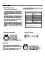
Specifications
subject to
change
without
notice.

3
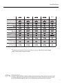
Model M2-65
M2-65B
M2-8
M2-8B
M2-8H
M2-8HB
M2-10H
M2-10HB
M2-TS
Nominal Size - inch (mm) 6.5”
(165mm)
8”
(203mm)
8”
(203mm)
10”
(254mm)
1”
(25.4mm)
Description 2-Way 2-Way 2-Way 2-Way 1-Way
Nominal Impedance
(Ohms) 4Ω 4Ω 4Ω 4Ω 4Ω
Frequency Response (Hz) 40-24kHz 35-24kHz 20-25kHz 20-25kHz 1425-25kHz
Power Handling - Watts
(RMS/Peak) 150/600 250/1000 300/1200 300/1200 200/800
Sensitivity (2.83V/1M) 91.8dB 93.1dB 94dB 97dB 97dB
Grille/Trim Ring YES YES YES YES Integrated
LED Current Draw .25 Amps .25 Amps .25 Amps .25 Amps N/A
Recommended Fused
Rating 1 Amp 1 Amp 1 Amp 1 Amp N/A
LED Voltage Range 9-16 Volts 9-16 Volts 9-16 Volts 9-16 Volts N/A
Specifications
Model
Ml-65
M2-8 M2-8H M2-10H
Ml-TS
Ml-65B
M2-8B M2-8HB M2-10HB
Nominal
Size
-inch (mm)
6.5
"
8" 8"
10" 1"
(165mm) (203mm) (203mm) (254mm) (25.4mm)
Description 2-Way 2-Way 2-Way 2-Way 1-Way
Nominal Impedance 4D 4D 4D 4D 4D
(Ohms)
Frequency Response
(Hz)
40-24kHz 35-24kHz 20-25kHz 20-25kHz 1425-25kHz
Power Handling -Watts 150/600 250/1000 300/1200 300/1200 200/800
(RMS/Peak)
Sensitivity
(2.83V/1M)
91.8d8
93.ldB
94dB 97d8 97dB
Grille/Trim Ring
YES YES YES
YES
Integrated
LED
Current Draw .25Amps .25Amps .25Amps .25Amps
N/A
Recommended Fused
Rating
lAmp lAmp lAmp lAmp
N/A
LED
Voltage Range 9-16 Volts 9-16 Volts 9-16 Volts 9-16 Volts
N/A
*
Rockford
Fosgate
determines
its
rated
frequency
response
range
at -6
dB
below
its
nominal
sensitivity
VERlFlEDwm-t
~
KLIPPEL
'--../
at
upper
and
lower
extents
of a
speaker's
output.
VERIFIED
WITH
KLIPPEL
Ta
adorn
the 'Verified
with
Klippel'
mark,
the
qualifying
company's
loudspeaker
engineering
personnel
must
be
trained
and
certified
by
Klippel
prior
ta
using the three
separate
Klippel
systems
to
design, develop
and
test. Rockford Fosgate
has
made
the
investment
in
Klippel
to
deliver
the
best
possible speakers
and
subwoofers
to
their
customers.

4
B
C
D
E
A
F
G
B
C
D
E
A
F
G
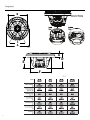
Model M2-65
M2-65B
M2-8
M2-8B
M2-8H
M2-8HB
M2-10H
M2-10HB
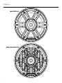
Overall Diameter
(A)
7.05”
(179.12mm)
9.07”
(230.4mm)
9.07”
(230.4mm)
11.53”
(292.8mm)
Screw Mounting
Diameter (B)
6.12”
(155.5mm)
7.76”
(197mm)
7.76”
(197mm)
10.08”
(256mm)
Mounting Screw
Angle (C) 6@60° 6@60° 6@60° 6@60°
Overall Height
(D)
3.54”
(90mm)
4.58”
(116.4mm)
4.58”
(116.4mm)
5.97”
(151.5mm)
Mounting Depth
(E)
2.49”
(63.2mm)
3.35”
(85mm)
3.35”
(85mm)
4.66”
(118.4mm)
Cut-out Diameter
(F)
5.36”
(136.2mm)
7.05”
(179.1mm)
7.05”
(179.1mm)
9.25”
(234.8mm)
Grill Height
(G)
1.03”
(26.1mm)
1.23”
(31.4mm)
1.23”
(31.4mm)
1.30”
(33.1mm)
Diagrams
Connector Closeup
Bottom
View
~~=~
illus.-1.1
illus.-2.1
Model M2-65 M2-8 M2-8H M2-10H
M2-65B M2-8B M2-8HB M2-10HB
Overall Diameter 7.
05"
9.07" 9.
07"
11.53"
(A)
(179.12mm) (230.4mm) (230.4mm) {292.8mm)
Screw Mounting 6.12" 7.76" 7.
76
" 10.08"
Diameter
(B)
(155.5mm) {197mm) (197mm) (256mm)
Mounting Screw 6@60°
6@60°
6@60°
6@60°
Angle(C)
Overall Height 3.
54"
4.58" 4.
58"
5.97"
(D)
(90mm) (116.4mm) (116.4mm) (151.5mm)
Mounting Depth 2.49" 3.35" 3.
35"
4.66"
(E)
(63
.2mm) (85mm) (85mm) (118.4mm)
Cut-out Diameter 5.36" 7.05" 7.
05"
9.25"
(F)
(136.
2mm)
(179.1mm) (179.1mm) (234.8mm)
Grill Height
1.03"
1.23"
1.23"
1.30"
(G)
(26.1mm) (31.4mm) (31.4mm) (33.1mm)

5
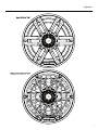
Diagrams
Sport Grill 6.5" &
8"
Stainless Steel Grill 6.5" &
8"

6
Diagrams
Sport Grill
SH
& lOH
Stainless Steel Grill
SH
& lOH

7
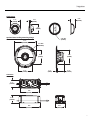
3.9” Dia.
(100mm)
4.3”
(110mm)
2.1”
(54mm)
0.4”
(9mm)
1.8”
(44mm)
1.4”
(37mm)
0.3”
(6mm)
2.8”
(71mm)
3.7”
(93mm)
4.3”
(108mm)
1.9”
(48mm)
2.8”
(71mm)
3.6”
(91mm)
1.3”
(33mm)
1.5”
(39mm)
0.9”
(23mm)
2.4” Dia.
(60mm)
Optional Horn Loading Mounting Flange
Flush Mount
Crossover
Diagrams
1
~:-~
=l-rn=---ll-H
~-======
-------++-ll------l:::::=======10=:i
1.

8
COLOR OPTIX™ WIRING OPTIONS
LED OUTPUT COLOR CONNECT THIS COLOR WIRE
TO GROUND
RED RED
GREEN GREEN
BLUE BLUE
YELLOW RED & GREEN
PINK RED & BLUE
AQUA GREEN & BLUE
WHITE RED, GREEN & BLUE
Connect colored wires on right to make output color
on le.
Connect all Yellow wires together to switched 12
Volts. See Wiring Precautions.
illus.-4.2
Included
Wiring
COLOR
OPT/XT"'
Wiring
COLOR
OPTIXT"'
Wiring Precautions
Do
not
connect
to
24 Volt electrical systems
We
recommend
only
using the
COLOR
OPTIX"'
wiring
chart
or
connecting to the
PMX-RGB.
Connecting
any
other
way
could cause damage
to
the speakers
or
the device
you
have
connected
to
.
We
recommend
installing
a fuse
(not
included) on the
Yellow 12 Volt wire whenever
you
are
NOT
using the
PMX-
RGB
.
See
COLOR
OPTIX"'
wiring
chart
for
wiring
options.
Rockford recommends a
minimum
of
20 gauge wire when
hard
wiring
your
COLOR
OPTIX"' speakers.
Never wire the
COLOR
OPTIX"' lights
directly
to 12 volts.
Utilize
either
the
PMX-RGB
or
a toggle switch (
not
included)
connected
to
a fused 12
volt
power
supply
. Refer to the
specifications
to
determine the size
of
fuse
(not
included)
needed
COLOR
OPTIX™
Pin
Out (wire
side)
1 -
RED
(Ground
Input)
2 -Yellow (12V +
Input)
3 -Blue (Ground
Input)
4 -Green (Ground
Input)
Included with speakers
Connector
is
DEUTSCH
™/Amphenol style
DT06-4S
i/lus.-4.1
SPEAKER
Wiring
There are
(2)
different options for wiring
your
speakers.
Use
the included spade connectors (included) as seen in illustra-
tion
3.1
You
can also utilize the
DEUTSCH™/Ampaenol
connector (not
included)
input
next to the
COLOR
OPTJX™
connector.
If
not
using the
PMX-RGB,
follow the diagrams below for proper
pin
out
and
hardwiring instructions.
COLOR
OPT/X™
Connector
-
11---,::;__
11-~-Ja:;:::::p
1 2
00
Speaker Pin
Out
(wire side)
1-
RED- Positive Speaker
Input
2 -BLACK -Negative Speaker
Input
NOT
included with speakers
Connector
is
DEUTSCH™
style
DT06-2S
i/lus.-4.3

9
Contents
(1)
Pair Marine Grade Speakers
(1)
Pair Removable Marine Grade Sport Grills
(1)
Pair
of
Stainless Steel Grill Inserts
(13)
Socket head stainless screws
(2)
Socket head driver
bit
(2)
RGB
Harness
(1)
PairofM2-TS Tweeters
(M2
-
TS
ONLY)
(1)
Pa
ir External lBdB/Oct Crossover(M2-
TS
ONLY)
(1)
Pair Flush Mount Clamps(M2-TS
ONLY)
(1)
Pair Horn Loading Mounting Flange
w/
O-rings(M2-TS
ONLY)
Installation
Considerations
Before beginning
any
installation, follow these simple rules:
Be
sure to carefully read
and
understand the instructions
before
attempting
to install these speakers.
For easier assembly, we suggest you run
all
wires
prior
to
mounting
your
speakers in place.
Use
high
quality
connectors for a reliable installation
and
to minimize signal
or
power
loss.
Think before you drill!
Be
careful
not
to
cut
or
drill
into gas
tanks, fuel lines, brake
or
hydraulic lines, vacuum lines
or
electrical wiring when working on
any
vehicle.
If
installation
in a boat, take care
not
to
cut
or
drill
through the main
hull
.
Never run wires underneath the vehicle. Running the wires
inside the vehicle
or
hull
area provides the best protection.
Avoid running wires over
or
through sharp edges.
Use
rubber
or
plastic grommets to protect
any
wires routed
through metal, especially the firewall.
Installation
Mounting
Determine where the speakers
will
be mounted. Ensure an
area large enough for the speaker to
mount
evenly.
Be
sure
that
the mounting location
is
deep enough for the speaker
to fit;
if
mounting in a door, operate
all
functions (windows,
locks, etc.) through their entire operating range to ensure
there
is
no obstruction.
Refer to the specification
chart
to determine the proper
diameter hole to
cut
for
your
speaker model. Cutting
and
mounting templates can be found
at
www
.rockfordfosgate.
com.
Mark the locations for the mounting screws. Drill the holes
with a
1/8
" bit.
Feed the speaker wires through the
cutout
and
connect to
the speaker terminals.
Be
sure to observe proper
polarity
when connecting the wires.
The
speaker's positive terminal
is
indicated with a "+'
'.
Fit the trim ring over the speaker
and
mount
into place
using the four
(4)
screws
that
are provided.
Tighten the screws
until
the speaker
is
snug in place to
prevent
rattling
.
Do
not
over tighten the screws.

10
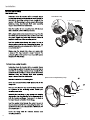
Flush Mount Clamp
Use tip of small flat screwdriver to
remove tweeter
Panel
Optional Horn Loading Mounting Flange
Flange
O-ring
Tweeter
Retainer
Flush Mount Clamp
Use tip of small flat screwdriver to
remove tweeter
Panel
Optional Horn Loading Mounting Flange
Flange
O-ring
Tweeter
Retainer
Installation
Mounting
(M2-TS
ONLY)
Flush Mount Option
Determine where the tweeter will
be
mounted. Ensure
an
area
large enough for the tweeter
to
mount evenly.
Be
sure
that
the mounting location
is
deep enough for the
tweeter
to
fit;
if
mounting
in
a door, operate all functions
(windows, locks, etc.) through their entire operating
range
to
ensure there
is
no obstruction.
Mark the location for the mounting hole. Drill the hole
with a standard 1.75 inch (45mm) hole
saw.
With a single center screw secure the inner cup from the
front
of
the door panel
to
the outer cup from back
of
the
door panel. Tighten the screw until balanced pressure
is
applied
to
both
faces
of
the mounting surface.
Feed
the speaker wires through the cutout.
Be
sure
to
observe proper polarity when connecting the wires. The
speaker's lead wires are indicated with a
WHITE
wire"+"
and a
BLACK
wire"
-
".
Simply snap the tweeter into place and secure with
a snap-on trim ring. Removal
is
easy
if
needed. The
protective grille on the tweeter
is
non-removable and
an
integral part
of
the design.
Optional Horn Loading Mounting
Determine where the tweeter will
be
mounted. Ensure
an
area
large enough for the speaker
to
mount evenly.
Be
sure
that
the mounting location
is
deep enough for the
speaker
to
fit
;
if
mounting in a door, operate all functions
(windows, locks, etc.) through their entire operating
range
to
ensure there
is
no obstruction.
Mark the location for the mounting hole.
Cut
or
use
a hole saw
to
drill a 3-5/8" (91mm) hole for the
flange
to
fit.
Once
you have the hole cut, insert the flange and mark
the locations for the mounting screws. Predrill your
mounting screw holes.
Assemble the horn flange, o-ring, tweeter and retaining
ring together.
Pay
close attention
to
the alignment tab on
both the tweeter and flange. These need
to
be
lined up
for proper tweeter orientation in the flange.
Feed
the speaker wires through the cutout.
Be
sure
to
observe proper polarity when connecting the wires. The
speaker's lead wires are indicated with a
WHITE
wire "+"
and a
BLACK
wire
"-
".
Secure the flange with the included stainless steel
mounting hardware.

11
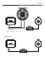
Add On M2T-S Tweeter with M2 Speaker
Individual Tweeter
Full Range Amplifier
Crossover
Tweeter
Full Range Amplifier
Crossover
Tweeter
Full-Range Speaker (M2)
4Ω
2Ω - When above 3KHz
NOTE: Your amplifier needs to be 2Ω stable per channel when
wired in this configuration.
Installation
□

24
Rockford Corporation offers a
limited
warranty
on Rockford Fosgate products on the following terms:
Length
of
Warranty
POWER
Amplifiers -2
Years
BMW
® Direct Fit Speakers -2
Years
PUNCH
® &
PRIME®
Amplifiers
-1
Year
Speakers, Signal Processors, Accessories
and
Capacitors
-1
Year
All marine, motorcycle, motorsport products -2
Years
Any Factory Refurbished
Product-
90 Days (receipt required)
What
is
Covered
Warranty
This
warranty
applies only to Rockford Fosgate products sold to consumers
by
authorized Rockford Fosgate dealers in the United
States
of
America. Products purchased
by
consumers from an Authorized Rockford Fosgate Dealer in
another
country are covered
only
by
that
country's Distributor
and
not
by
Rockford Corporation.
Who
is
Covered
This
warranty
covers only the
original
purchaser
of
Rockford
product
purchased from an authorized Rockford Fosgate dealer in the
United States. In order to receive service, the purchaser
must
provide Rockford with a copy
of
the receipt stating the customer name,
dealer name,
product
purchased
and
date
of
purchase.
Products found to be defective during the
warranty
period
will
be repaired
or
replaced (with a
product
deemed to be equivalent)
at
Rockford's discretion.
What
is
Not
Covered
Damage caused
by
accident, abuse, improper installation, operations, theft,
water
(on non-Element Ready products).
Any cost
or
expense related to the removal
or
reinstallation
of
product.
Service performed
by
anyone
other
than Rockford
or
an authorized Rockford Fosgate service center.
Any
product
which has
had
the serial
number
defaced, altered,
or
removed.
Subsequent damage to
other
components.
Any
product
purchased outside the
U.S.
Any
product
not
purchased from an authorized Rockford Fosgate dealer. Refer to rockfordfosgate.com dealer locator for more
detail.
Limit
on
Implied
Warranties
Any implied warranties including warranties
of
fitness for use
and
merchantability
are
limited
in duration to the
period
of
the express
warranty
set forth above. Some states do
not
allow
/imitations on the length
of
an
implied
warranty, so this limi
tation
may
not
apply.
No
person
is
authorized to assume for Rockford Fosgate
any
other
liability
in connection with the sale
of
the product.
How
to
Obtain
Service
Please call 1-800-669-9899 for Rockford Customer Service.
You
must
obtain an
RA#
(Return Authorization number) to return
any
prod-
uct
to Rockford Fosgate.
You
are responsible for shipment
of
product
to Rockford.
EU
Warranty
This
product
meets the current
EU
warranty
requirements,
see
your
Authorized dealer for details.

Installat
i
on ass
i
stance ava
i
lable at:
0
--.,J
N
N
N
0
N
N
,_.
t;:l
0
-'..J
w
0
N
N
6
','
rn
~
:::,
fu"
0..
:::,
n
:::,-
5·
"'
www. rockfo rdfosgate .com/ rftech
600
South
Rockford
Drive•
Tempe,
Arizona
85281
United
States
Direct:
(480)
967-3565
• Toll
Free:
(800)
669-9899
rockfordfosgate.com
-
 1
1
-
 2
2
-
 3
3
-
 4
4
-
 5
5
-
 6
6
-
 7
7
-
 8
8
-
 9
9
-
 10
10
-
 11
11
-
 12
12
-
 13
13


Rockford Fosgate 575M265 M2-65 Manuel utilisateur
- Catégorie
- Accessoires de moto
- Taper
- Manuel utilisateur
dans d''autres langues
Documents connexes
-
Rockford Fosgate ELEMENT READY M2-8HB Installation & Operation Manual
-
Rockford Fosgate M2WL-10H Le manuel du propriétaire
-
 Rockford Fosgate M2WL-8 Manuel utilisateur
-
Rockford Fosgate M1WL-65MB Mode d'emploi
-
 Rockford Fosgate M1D2-8 Manuel utilisateur
-
 Rockford Fosgate M2 ELEMENT READY M2D4-10S Manuel utilisateur
-
 Rockford Fosgate Element Ready M2D4-10I Installation & Operation Manual
-
 Rockford Fosgate P152-S Manuel utilisateur
-
Rockford Fosgate Punch PM282HW Manuel utilisateur
-


