
WAC Lighting retains the right to modify the design of our products at any time as part of the company's continuous improvement program. SEPT 2022 1
waclighting.com
Phone (800) 526.2588
Fax (800) 526.2585
Headquarters/Eastern Distribution Center
44 Harbor Park Drive
Port Washington, NY 11050
Central Distribution Center
1600 Distribution Ct
Lithia Springs, GA 30122
Western Distribution Center
1750 Archibald Avenue
Ontario, CA 91761
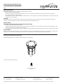
INSTALLATION INSTRUCTION
COLORSCAPING INGROUND
5831
SAFETY INSTRUCTION
IMPORTANT: NEVER attempt any work without shutting o the electricity.
• Read all instructions before installing.
• System is intended for installation by a qualied electrician in accordance with the National Electrical Code and local regulations.
• Place the wall switch in the “OFF” position.
• Go to the main fuse box, or circuit breaker. Unscrew the fuse(s) or switch ”OFF” the circuit breaker switch(es) that control the power to the
space that you are working on.
CAUTION:
All parts must be used as indicated in these instructions. Do not substitute any parts, leave parts out, or use any parts that are worn out
or broken. Failure to follow this instruction could invalidate the UL/cUL listing of this fixture.
AVERTISSEMENT
IMPORTANT : COUPEZ L’ÉLECTRICITÉ AVANT TOUTE MANIPULATION.
• Lisez toutes les instructions avant d’installer.
• Système est destiné à être installé par un électricien qualié en conformité avec le code national de l’électricité et les règlements locaux.
• Placez l’interrupteur mural en position d’arrêt (« OFF »).
• Accédez au panneau central de disjoncteurs ou de fusibles de votre demeure et placez l’interrupteur principal en position d’arrêt (« OFF »).
MISE EN GARDE
Toutes les pièces doivent être utilisées tel qu’il est indiqué dans ces instructions. Ne remplacez pas les pièces, n’en laissez pas de côté et ne les
utilisez pas si elles sont usées ou brisées. Le non-respect de ces instructions peut annuler l’homologation UL du luminaire.
5831
Fixture Accessory (included in box)
Outdoor Rated Wire Nut
Qty: 2pcs
This instruction apply to the model(s) below:
**Note: WAC Smart Transformer is required to power the fixture. (sold separately)

WAC Lighting retains the right to modify the design of our products at any time as part of the company's continuous improvement program. SEPT 2022 2
waclighting.com
Phone (800) 526.2588
Fax (800) 526.2585
Headquarters/Eastern Distribution Center
44 Harbor Park Drive
Port Washington, NY 11050
Central Distribution Center
1600 Distribution Ct
Lithia Springs, GA 30122
Western Distribution Center
1750 Archibald Avenue
Ontario, CA 91761
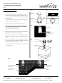
1. Turn the main power off.
2. Install wiring and conduit (use 1/2” NPT) with Concrete Pour
Canister at desired position, plug all un-used holes (Fig. 1)
Secure the canister to the bottom of the application ground
by using screws.
Note: For proper alignment, make sure the flat edge of the
canister is parallel to the wall. (Fig. 2)
3. Insert Plastic Cap into Concrete Pour Canister (Fig. 1)
4. Pour concrete until it’s flushed with the Plastic Cap. (Fig. 3)
Note: NO CONCRETE ENTERS THE BOX. USE SAND OR
GRAVEL FOR PROPER DRAINAGE.
5. After concrete has cured, crack concrete and remove Plastic
Cap using a corkscrew or similar tool. (Fig. 4)
6. Connect fixture leads to box wiring using supplied outdoor
rated wire nuts. Make sure all power is off while wiring LED
fixture.
7. Apply a smear of plumber’s silicone to O-rings. Insert LED
fixture into flange with a twisting motion. Make sure the trim
is flushed with the top of the poured concrete.
8. To match different height requirements, use extenders and
cover plates. (Fig. 5)
CONCRETE POUR INSTALLATION Fig.1 Fig.2
Fig.3
Fig.4
Fig.5
Plastic Cap
Concrete
Sand or pea gravel
(For Drainage)
Sand or pea gravel
(For Drainage)
1/2” NPT pipe extender
(Not Provided)
4” Junction box cover
(Not Provided)
LED Fixture
Outdoor Rated
Wire Nuts
Concrete
O-Rings
Soil
Soil
Concrete Pour
Canister
1/2” NPT
Wall
Parallel
INSTALLATION INSTRUCTION
COLORSCAPING INGROUND
5831

WAC Lighting retains the right to modify the design of our products at any time as part of the company's continuous improvement program. SEPT 2022 3
waclighting.com
Phone (800) 526.2588
Fax (800) 526.2585
Headquarters/Eastern Distribution Center
44 Harbor Park Drive
Port Washington, NY 11050
Central Distribution Center
1600 Distribution Ct
Lithia Springs, GA 30122
Western Distribution Center
1750 Archibald Avenue
Ontario, CA 91761
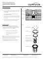
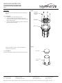
SOFTSCAPE INSTALLATION
CUSTOMIZE SETTING
1. Turn the main power off.
2. Dig a hole at the point of application. Make sure the hole
measures at least 4-3/4 inches in diameter and 10 inches
in depth. (Fig.6)
3. Place a layer of pea gravel (3 inches) at the base of the
hole to help with drainage.
4. Connect the fixture wires to landscape wires coming from
the transformer using the outdoor rated direct burial wire
nuts provided.
5. Place the fixture in the hole and repack the soil to hold it
in place. Make sure the trim is flush with the ground.
This fixture is equipped with two customizable settings:
Beam Angle Adjustment, and Beam Aiming Adjustment. It
can be pre-set into desired settings by taking the light engine
assembly out from the fixture housing. (Fig. 7)
1. Unscrew Face Plate Screws with hex L-key.
2. Take out the Face Plate, Gasket, Front Glass
3. Pull the Light Engine out of the Fixture
housing.
Note: Light Engine can be taken out remotely by disconnecting
the Quick Connector. Users can later reconnect it back into the
housing after all desired settings are been made.
To ensure IP67 rating of the xture, use a minimum force of
2.5 N*M/22 lbsf.in to tighten the screws of the face plate.
Fig.6
Fig.7
Soil
Outdoor Rated
Wire Nut
From
Transformer
To Next
Fixture 4 3/4”
13”
3”
Pea Gravel
INSTALLATION INSTRUCTION
COLORSCAPING INGROUND
5831
Faceplate Screws
Faceplate
Gasket & Front Glass
Beam Adjustment Dial
Light Engine
Fixture Housing
Aiming Adjustment

WAC Lighting retains the right to modify the design of our products at any time as part of the company's continuous improvement program. SEPT 2022 4
waclighting.com
Phone (800) 526.2588
Fax (800) 526.2585
Headquarters/Eastern Distribution Center
44 Harbor Park Drive
Port Washington, NY 11050
Central Distribution Center
1600 Distribution Ct
Lithia Springs, GA 30122
Western Distribution Center
1750 Archibald Avenue
Ontario, CA 91761
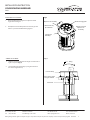
BEAM ANGLE ADJUSTMENT:
AIMING ADJUSTMENT:
1. Rotate the Beam Changing Dial to adjust the beam
angle with two fingers.
2. The Optical Lens Assembly will move vertically up and
down as you rotate the Beam Changing Dial
1. Hold the Lens Assembly with two fingers and tilt it left or
right as required. (Fig. 9)
2. Lens Assembly will be fixed by a spring mechanism to
the desired angle full stop.
Fig.8
Fig.9
INSTALLATION INSTRUCTION
COLORSCAPING INGROUND
5831
Light Engine
Assembly
Optical Lens Assembly
Moves Vertically
Up and Down
Beam Changing Dial
Rotates to Control
Optical Lens
Assembly
10°
20°
Beam Aiming Steps
10 Degrees Interval
Lens Assembly
Pivot Point
20 Tilting

WAC Lighting retains the right to modify the design of our products at any time as part of the company's continuous improvement program. SEPT 2022 5
waclighting.com
Phone (800) 526.2588
Fax (800) 526.2585
Headquarters/Eastern Distribution Center
44 Harbor Park Drive
Port Washington, NY 11050
Central Distribution Center
1600 Distribution Ct
Lithia Springs, GA 30122
Western Distribution Center
1750 Archibald Avenue
Ontario, CA 91761
ACCESSORIES:
• Rock Guard – Protects xture front glass from large falling
objects.
To Install (Fig. 10):
1. Unscrew the Face Plate Mounting Screws.
2. Put the Rock Guard on top of the xture face plate,
make sure to match up the mounting index arrow on the
xture and rock guard.
3. Use the same Face Plate Mounting Screws to mount the
Rock Guard onto the xture.
• Concrete Pour Canister & Cap – used to install xture in
concrete pour applications.
To install (Fig. 11):
Please visit the previous Concrete Pour Installation instructions.
Fig.10
Fig.11
Plastic Cap
Concrete Pour
Canister
INSTALLATION INSTRUCTION
COLORSCAPING INGROUND
5831
Rock Guard
Fixture
Faceplate
Mounting
Screws
-
 1
1
-
 2
2
-
 3
3
-
 4
4
-
 5
5


WAC Lighting 5831 Mode d'emploi
- Taper
- Mode d'emploi
- Ce manuel convient également à
dans d''autres langues
Documents connexes
-
WAC Lighting 5033 Mode d'emploi
-
-
-
-
-
-
-
-
WAC Lighting 1061-27SS Mode d'emploi
-