
SERIAL
D1 D2 D3 D4
GND
DIO1
DIO2
DIO3
DIO4
GND
GND
- +
+24 LOOP
+12 COMS
GND
SDI-12
GND
AI1
- +
AI2
- +
RS485
1 2 3 4
1-HTR
2-SOL
3-GND
4-BAT
1 2 3 4 5
6 7 8 9
CONDOR
415U-1
Wireless I/O
PWR /OK
TX
RX
SENSOR
TEST MODE
TX TEST
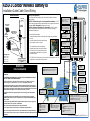
415U-1 Condor Wireless Battery IO
Installation Guide Cable Gland Wiring
COLINEAR
ANTENNA
MAST
OPTIONAL
PADLOCK
SURGE
ARRESTOR
(OPTIONAL)
COAXIAL CABLE
WEATHERPROOF
CONNECTORS WITH
“3M 23” TAPE
STRESS RELIEF
LOOP
PROVIDE GOOD GROUND
CONNECTION TO MAST, MODULE
AND SURGE ARRESTOR
CHASSIS
GND
IF GROUND CONDITIONS ARE
POOR, INSTALL MORE THAN
ONE STAKE
1 wavelength
minimum
415U-1
PWR /OK
TX
RX
SENSOR
TEST MODE
TX TEST
Wireless I/O
CONDOR
SOLAR PANEL
(See Notes)
Antenna Installation
Wavelength Guide
150MHz = 150cm
340MHz = 88cm
450MHz = 66cm
900MHz = 33cm
DO NOT DISCONNECT WHILE CIRCUIT IS LIVE UNLESS AREA IS KNOWN TO BE NON-
HAZARDOUS
NE PAS DÉBRANCHER PENDANT QUE LE CIRCUIT EST SOUS TENSION À MOINS QUE LA
ZONE SOIT CONNUE SOYEZ NON DANGEREUX
The 415U-1-C4-EX, 415U-1-C3-EX, 415U-1-C1-EX and 415U-1-C9-EX are suitable for use in Class 1,
Division 2, Groups A, B, C and D; Tamb –40° C to +70° C or non-hazardous locations only.
This equipment shall be installed in accordance with the requirements specified in Article 820 of the
National Electrical Code (NEC), ANSI/NFPA 70-2011. Section 820.40 of the NEC provides guidelines for
proper grounding, and in particular specifies that the antenna ground (shield) shall be connected to the
grounding system of the building, as close to the point of cable entry as practical.
The earth/ground terminal of this equipment shall be connected to earth ground in the equipment
installation.
The supplied Nylon Cable Glands and Blanking Plugs are rated UL94V-2 and are not suitable for
installations within Hazardous Locations. Use metal conduit or components with flammability rating
UL94V-1 or better.
The external power supply installed with this equipment shall be a listed, Class 2 power supply, with
rated output between 17 Vdc and 30 Vdc, and minimum 2A
DO NOT connect voltage to terminal 4-BAT when using an internal battery
NE PAS connecter la tension à la borne 4-BAT lors de l'utilisation d'une batterie interne
DO NOT connect voltage to terminal 2-SOL when using a Lithium Primary (non-rechargeable) battery
NE PAS connecter la tension à la borne 2-SOL lors de l'utilisation d'une batterie au lithium primaire (non
rechargeable)
WARNING!
EXPLOSION HAZARD
Battery Power Applications:
Units shipped with internal battery option, do not have the battery connected
during shipping.
CAUTION - Lithium Primary (LiP non-rechargeable) internal battery: DO NOT
connect external voltage directly to battery terminals or to supply/solar terminals as
this battery is NOT rechargeable and damage may result.
CAUTION - Lithium Iron Phosphate (LFP rechargeable): DO NOT connect
external voltage directly to battery terminals as this may result in damage or
overheating of battery pack.
To connect the internal battery:
· Remove the battery holder by removing the two Philips screws and battery
bracket.
· Locate the battery connector located at the top
right of battery as shown in picture.
· For internal battery connect the battery by
plugging battery cable connector onto the two
pin connector on circuit board located to right
of internal/external selection link, using correct
orientation (keyed).
· The PWR/OK LED green flash every 10 seconds in normal operation. See unit
configuration on reverse side of this document.
RS232:
Alternative Configuration
&Communications
DIGITALS:
Ꝋ GND:
Ꝋ DIO1: ON/OFF, Pulse
Ꝋ DIO2: ON/OFF, Pulse
Ꝋ DIO3: ON/OFF, Pulse
Ꝋ DIO4: ON/OFF only
Ꝋ GND:
ANALOGS:
Ꝋ GND:
Ꝋ AIN1 -/+: 4-20mA Current Loop
Ꝋ AIN2 -/+: 4-20mA Current Loop
Ꝋ LOOP: +24V Loop Supply
SENSOR / RS485:
Ꝋ GND:
Ꝋ +12COMMS: SDI-12 Power Supply
Ꝋ GND:
Ꝋ RS485 -/+: RS485 Modbus Smart Sensor.
Ꝋ SDI-12: SDI-12 Data IN/OUT.
Ꝋ GND:
TEST
SUPPLY:
Ꝋ 1 - HTR: Control for internal Heater
Ꝋ 2 - SOL: Solar Paanel 30W 2A Max or Ext Supply 17-30Vdc
Ꝋ 3 - GND: Enternal Power -ve supply
Ꝋ 4 - BAT: External Power 11-15Vdc
CONNECTIONS:
Wiring Entry: IP66 M20 Cable entry Gland (5-13mm)
Terminals: PushIN connection max 0.2 – 1.5mm
2
wire.
PWR / OK:
Green Flash 10Sec – Normal
Green ON – Active
Red Flash – Low Battery
TX:
Green – Transmitting data
Red – Transmit Fault/Failure
RX:
Green – Strong Signal
Red – Weak Signal
SENSOR:
Green – Analog Loop or SDI-
12 supply active
TEST MODE:
Green – Test transmission
TX TEST:
Short press (5Sec) – Send
test transmission
© ELPRO Technologies Pty. Ltd. 2020 Rev. 1.2
Battery
TEST:
Short press to send input
data message.
Long press (5sec) to send
logged data to USB
USB A:
Download Logged data /
Firmware upgrade
USB B:
Config / Diagnostics
RESET:
Reboot unit

CONFIGURATION
· You will need a terminal program to configure the
415U-1 unit. Putty or TerraTerm are free to
download for this purpose.
· Once you have terminal program installed run it and
connect the 415U-1 unit to the laptop using a USB
type A to type B cable (printer cable)
· Set the terminal serial data rate to 9600,n,8,1.
· Press enter and you should see a login as below:
a) Engineer
b) Technician
· There are two levels of user access. To configure
the unit, select menu option ‘a’ to select Engineer
access and enter the default password “Elproeng”
and a configuration menu will appear.
· Begin configuration by selecting option 'a' in the
menu and entering details as required.
· “Quick Setup” menu option provides a basic
configuration with default sensor inputs and
recommended update and paralysis to get started.
· Its recommended to use default settings through
Quick Setup menu option where possible for best
battery life.
·
Important Notices
ELPRO products are designed to be used in industrial environments by experienced industrial engineering personnel with adequate knowledge of safety design considerations. ELPRO radio products can be used unprotected license-free radio bands with
radio noise and interference. The products are designed to operate in the presence of noise and interference, but in an extreme case radio noise and interference can cause product operation delays or operation failure. Like all industrial electronic products,
ELPRO products can fail in a variety of modes due to misuse, age, or malfunction. We recommend that users and designers design systems using design techniques intended to prevent personal injury or damage during product operation and provide
failure tolerant systems to prevent personal injury or damage in the event of product failure. Designers must warn users of the equipment or systems if adequate protection against failure has not been included in the system design. Designers must include
this Important Notice in operating procedures and system manuals. These products should not be used in non-industrial applications, or life-support systems, without consulting ELPRO first. A radio license is not required in some countries, provided the
module is installed using the aerial and equipment configuration described in the Installation Guide. Check with your local distributor for additional information on regulations. Operation of unlicenced equipment is authorized by the radio frequency regulatory
authority in your country on a non-protection basis. Although all care is taken in the design of these units, there is no responsibility taken for sources of external interference. Systems should be designed to be tolerant of these operational delays. To avoid
the risk of electrocution, the aerial, aerial cable, data/IO cables and all terminals of the module should be electrically protected. To provide maximum surge and lightning protection, the module should be connected to a suitable ground and the aerial, aerial
cable, IO, data cables and the module should be installed as recommended in the Installation Guide. To avoid accidents during maintenance or adjustment of remotely controlled equipment, all equipment should be first disconnected from the module during
these adjustments. Equipment should carry clear markings to indicate remote or automatic operation. For example: “This equipment is remotely controlled and may start without warning. Isolate at the switchboard before attempting adjustments.” The
equipment operates unlicensed radio frequencies, proprietary protocols to communicate over the radio, cyber security features and encryption. Nevertheless, if your system is not adequately secured, third parties may be able to gain access to your data or
gain control of your equipment via the radio link. Before deploying a system, make sure that you have carefully considered the security aspects of your installation and read the user documentation.
Proper Use
Any unauthorized modifications to or use of this equipment outside its specified mechanical, electrical, or other operating limits may cause personal injury and/or property damage, including damage to the equipment. Any such unauthorized modifications:
(1) constitute “misuse” and/or “negligence” within the meaning of the product warranty, thereby excluding warranty coverage for any resulting damage; and (2) invalidate product certifications or listings.
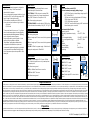
POWER SUPPLY
BAT (11-15Vdc): Internal battery if fitted or connect
external battery with 5A fast blow fuse.
SOL (17-30Vdc): 5-30W solar panel or external 24W
power supply to power unit or charge internal/external
battery (ONLY Lithium Iron Phosphate or SLA).
GND: Power supply system ground
HTR (30Vdc/2A MAX): Low side switch to GND to allow
for internal heater to warm battery. ON @ 0°C, OFF @ 2°C
4-20mA ANALOG INPUTS
GND: Analog input ground
AIN1 +/-: Analog input 2/3 wire, source/sink loop powered.
30Vdc max
AIN2 +/-: Analog input 2/3 wire, source/sink loop powered.
30Vdc max
+24 LOOP: 4-20mA Loop power supply. Switched on for
warmup plus sample period. 50mA MAX
SMART SENSOR
+12COMS: Power supply to SDI-12 sensor (500mA
MAX). Switched to power sensor only for warmup time
plus sample period.
GND: Smart sensor ground
RS485 +/-: Modbus Smart Sensor connection
SDI-12: Data IN/OUT for sensor
GND: Smart sensor ground
DISCRETE INPUTS
GND: Discrete inputs ground
DIO1: ON/OFF or pulse
DIO2: ON/OFF or pulse
DIO3: ON/OFF or pulse
DIO4: ON/OFF input
Note: Discrete input DRY contact close to
ground
NOTES:
All I/O connections must be SELV
Solar and external power supply/ battery charger:
(A) 17-30Vdc Supply or internal battery charger input, 2A
NEC Certified Class 2
(B) Solar panel to charge internal/external 12V battery
(30W, charge current 2.0A MAX)
(C) 11-15Vdc battery supply input
(D) DO NOT connect external supply to BAT terminal with
internal battery option connected.
Environmental Specification:
Ingress Protection IP66
Operating Temperature ext supply -40 to 70°C (-40 to
158°F)
LFP rechargeable battery -20 to 60°C (-4 to 140°F)
LiP non-rechargeable battery -40 to 70°C (-40 to
158°F)
Altitude 2000m
Pollution Degree 4
Internal Humidity Max 95% non-
condensing
GND
SDI-12
+
-
GND
+12 COMS
RS485
RS485
SDI-12
Sensor
1 – HTR
2 – SOL
3 – GND
4 – BAT
+
_
11-15V
Battery
17-30V
Supply
GND
- +
+24 LOOP
AI1
- +
AI2
Externally
powered sensor
Loop
powered
sensor
+
-
mA
+
-
Voltage
Free
Contact
Transistor
Switch
Device
GND
DIO1
DIO2
DIO3
DIO4
GND
TTL
CMOS
Output
© ELPRO Technologies Pty. Ltd. 2020 Rev. 1.2
-
 1
1
-
 2
2


ELPRO 415U-1 CONDOR SERIES Guide d'installation
- Taper
- Guide d'installation
- Ce manuel convient également à
dans d''autres langues
Autres documents
-
Contec CPS-MCS341-DS1-131 Guide de référence
-
ABB ACSM1-04 Series Quick Installation Manual
-
ABB ACS880-01-442A-3 Quick Installation Manual
-
-
ABB ACS850-04 series Quick Installation Manual
-
-
-
-
-