
CHILONE FLOOR 45 - 90 - UP
CHILONE WALL designed by E.Gismondi
E
D
C
C
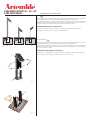
AVERTISSEMENTS
Déconnecter la tension de réseau avant toute opération sur l’appareil. ARTEMIDE S.p.a. décline
toute responsabilité pour les produits modiés sans autorisation préalable.
L’appareil requiert une base en béton A avec un puisard de drainage (g.1).Ne pas positionner
la base dans des zones où l’eau stagne.Jeter le béton dans le lieu choisi en prévoyant le passage
de la gaine plissée B au centre.
INSTRUCTIONS DE MONTAGE FLOOR 45-90-UP
Retirer les 4 vis C. Désenler la colonne D du support de l’appareil E (g.2). Utiliser le support
E comme gabarit pour marquer la position des trous F à percer. (Fig.3)
NOTE
Prior to any work on the xture always switch off the mains.ARTEMIDE S.p.a. does not shoulder
any responsibilities for products which are modied without prior authorisation.
The light tting requires a concrete base-plate A with draining well (g.1). Do not position the
base-plate where water may stagnate. Cast concrete in the position selected and take care to
leave the passage for routing the corrugated sheath B through the centre.
ASSEMBLY INSTRUCTIONS FLOOR 45-90-UP
Loosen the 4 screws C. Remove column D from light tting mounting E (g.2). Using
mounting E as a template, mark positions for holes F (g.3).
F
EN
g. 3
F
F
F
E
g. 2
g. 1
A
B

D
C
4 X
C
F
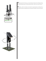
Pour la xation, utiliser les chevilles pour ancrages lourds ( g.4). Effectuez le câblage selon le
polaritè blanc / blanc, noir / noir et vert / vert avec une connexion résistant à l’eau. Placez le joint
à l’intérieur du puisard de drainage faits plus tôt. Remonter la colonne D. Serrer les 4 vis C ( g.5).
Use heavy-duty screw anchors ( g. 4). Carry out the wiring according to the polarity white / white,
black / black and green / green creating a water-resistant connection. Fit the connection inside
the draining well made earlier. Put column D back into place. Screw in the 4 screws C ( g.5).
EN
4 X
g. 4
Tenendo premuto il fermo di sicurezza H, fare scorrere il cavetto d'acciaio F fino al segno
precedentemente marcato. Ripetere l'operazione per gli altri due cavetti d'acciaio (fig.4).
Segnare sul soffitto la posizione dei 4 fori a 90° I
del fondello B. Forare con punta di sezione
adeguata al tassello ad espansione scelto. Far passare i cav i elettrici provenienti dal muro
attraverso il foro L
del fondello B e fissare il fondello al soffitto. Posizionare la piastra C sul
fondello B
attraverso le asole M e stringere le viti (fig.5).
Eseguire i collegamenti elettrici all'apposito morsetto N
. Collegare il cavo di messa a terra in
corrispondenza del simbolo , facendo attenzione a inserire il cavo al di sotto della lamella
presente in corrispondenza della vite O
. Se fosse necessario bilanciare l’apparecchio, allen-
tare uno dei tre fermi H
, spingere il fermo verso il soffitto e far scorrere il cavo di sostegno,
riavvitare il fermo di sicurezza H
(fig.6).
I
I
I
L
M
M
B
H
F
Fig.5
Fig.6
Fig.4
H
H
H
O
N
I
I
C
Presser l’arrêt de sécurité H, faire glisser le câble d’acier F jusqu’au point marqué auparavant.
Répéter l'opération pour les deux autres câbles d’acier (fig.4).
Marquer sur le plafond la position des 4 trous de 90° I
du culot B. Percer au moyen du foret
approprié à la cheville à expansion choisie. Faire passer les câbles électriques sortant du mur
à travers le trou L
du culot B et le fixer au plafond. Positionner la plaque C sur le culot B à
travers les trous oblongs M
et serrer les vis (fig.5).
Brancher à la borne adéquate N
. Connecter le câble de mise à la terre près du symbole ,
en faisant attention à insérer le câble au-dessous de la plaque présente près de la vis O
. Au
cas où il serait n écessaire de balancer la lampe, desserrer un des trois arrêts H
, pousser
l’arrêt vers le plafond et faire glisser le câble de support; ensuite revisser l’arrêt de sécurité H
(fig.6).
Pres s retainer H and make the steel cable F slide up to the previous mark. Repe at the
operation for the other two steel cables (fig.4).
Mark on the ceiling the position of the 4 90° holes I
of the bottom plate B. Drill with the
proper drill for the chosen screw anchor. Make the electric cables coming from the wall go
through hole L
of the bottom plate B and fix it to the ceiling. Position plate C on the bottom
plate B
by means of slots M and tighten the screws (fig.5).
Carry out the electrical connections to t he proper terminal N
. Conn ect the ground cable
near symbol , being careful to insert it under the plate located near screw O
. In case the
lamp should be balanced, loosen one of the three retainers H
, push the retainer toward the
ceiling and make the support cable slide, screw the retainer H
again (fig.6).
Die Haltevorrich tung H von dem Kabe l drücken und die Stahllitze F bis das vorh erige
Ken nzeichen gleite n lassen. Die se Operation auch für di e andere n zwei S tahllitz en
wiederholen (Abb.4).
Die Position der 4 90° Löcher I
des Bodens B auf der Decke kennzeichnen. Mit einem Bohrer
dem gew ählten Spreizdübel entsprechend durchbohren. Die aus dem Mauer kommenden
Stromkabel durch das Loch L
des Bodens B durchlegen und ihn auf der Decke befestigen.
Positionieren Sie die Platte C
durch die Ösen M am Boden B und ziehen Sie die Schrauben
fest (Abb.5).
Di e Stromkabe l an die geeignet e Klemme N
anschließen. Das Erdungs kabe l bei dem
Symbol anschließen . Dabei darauf achten, dass das Kabel unter die Lamelle neben der
Schraube O
gesteckt ist. Wenn die Lampe ausgewogen werden soll, lösen Sie eine der drei
Haltevorric h tungen H
, schieben Sie sie an der Decke und das Stütz seil gleiten lassen,
schrauben Sie die Haltevorrichtung H
(Abb.6).
Manteniendo presionado el dispositivo de fijación de seguridad H, hacer deslizar el cable de
acero F
hasta alc an zar el punto marcado anteriormente. Repetir esta operación para los
demás cables de acero (fig.4).
Marcar en el techo la posición de los 4 agujeros de 90° I
del fondo B . Perforar utilizando una
punta adecuada para el tipo de taco de expansión utilizado. Hacer pasar los cables eléctricos
procedentes de la pared a través del agujero L
del fondo B, y fijar el fondo al techo. Poner
la placa C
en el fondo B mediante las ranuras M y apretar los tornillos (fig.5).
Efectuar las conexiones eléctricas al borne adecuado N
. Conectar el cable de puesta a tierra
en correspondencia del símbolo , teniendo cuidado con poner el cable bajo la lámina en
correspon dencia del tornillo O
. Si fuera necesario equilibrar el aparato, aflojar uno de los
tres dispositivos de fijación H
, empujarlo hacia el techo y hacer deslizar el cable de soporte;
atornillar nuevamente el dispositivo de fijación de seguridad H
(fig.6).
F
EN
D
E
4 X
g. 5

g. 6
g. 7
g. 8
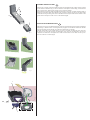
INSTRUCTIONS DE MONTAGE PAROI
Enlever les 2 vis G avec rondelle et extraire le corps de l’appareil H ( g.6). Percer selon l’orientation
désirée ( g.7). Utiliser l’étrier I comme gabarit de perçage. Pour la xation utiliser des chevilles
pour les ancrages lourds. Dévisser le couvercle de fermeture L de l’étrier I.
Siliconer le bord de la j-box et xer l’étrier I à la paroi. Connecter le câble noir de la j-box avec
le câble noir du corps de l’appareil, le câble blanc de la j-box avec le câble blanc du corps de
l’appareil et le câble vert de l’appareil et le câble vert de l’étrier avec le câble vert de la j-box.
Fixer le couvercle L à l’étrier.( g.8).
F
EN
ASSEMBLY INSTRUCTION WALL
Remove the 2 screws G with the washer and take out the xture body H ( g.6). Drill according
to the desired orientation ( g.7). Use the bracket I as template. For the xing, use dowels for
heavy duty anchors. Unscrew the closing cover L from the bracket I.
Apply silicone on the jbox edge and fasten the bracket I to the wall. Connect the black cable of
the jbox to the black cable of the xture body, the white cable of the jbox to the white cable
of the xture body and the green cable of the xture and the green cable of the bracket to the
green cable of the jbox. Fix the cover L to the bracket ( g.8).
H
G
I
I
L
4 X

LIGHT SOURCE
SOURCE LUMINEUSE
TERRA 45/ 90 : LED 8W
UP / PARETE: LED 15W
Artemide reserves the right to introduce all the technical and structural changes required for the improvement of the product.
Artemide se réserve d’apporter à n’importe quel moment toute modi cation technique et structurelle qu’on trouve nécessaire pour l’amélioration du produit.
Warning: this equipment is guaranteed only when used as indicated in these instructions. Therefore they should be kept for future reference.
Attention: la sécurité de l’appareil n’est garantie que si les instructions sont convenablement suivies. Il est donc nécessaire de les conserver.
In case of complaint, please quote number
En cas de réclamation, veuillez citer le numéro
cod. Y503002120A
Via Bergamo, 18
I-20010 Pregnana M.se (MI) - ITALIA
t. +39 02.935.18.1 f. +39 02.935.90.254-496
www.artemide.com
P. Iva IT 00846890150
LED REPLACEMENT
The xture is provided with a light source having a long life. Anyway, if the led needs to be replaced, this operation must be carried out only by our specialized staff.
Therefore, we recommend contacting the nearest dealer. For the addresses of Artemide dealers in the world, visit our website: www.artemide.com.
REMPLACEMENT LED
Une source avec une vie utile très longue est jointe à l’appareil. De toute façon, au cas où il serait nécessaire de remplacer le led, cette opération devra être effectuée
exclusivement par notre personnel spécialisé. Vous êtes donc priés de vous adresser au distributeur le plus proche. Pour les adresses des distributeurs Artemide dans le
monde, visiter le site: www.artemide.com.
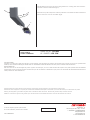
H
I
G
g. 9
Put light tting body H back into place paying attention to correctly place cable inside of it.
Screw the 2 screws G with washer ( g.9).
Remonter le corps de la lampe H en veillant à positionner correctement le câble à l’intérieur de
celle-ci. Serrer les 2 vis G avec la rondelle ( g.9).
-
 1
1
-
 2
2
-
 3
3
-
 4
4


Artemide Chilone Floor 45 Guide d'installation
- Taper
- Guide d'installation
- Ce manuel convient également à
dans d''autres langues
Documents connexes
-
Artemide TOLOMEO LED MWL Manuel utilisateur
-
-
-
-
-