
1
DISHWASHER
LAVE-VAISSELLE
Models/Modèles :
DW183WADA DW184BADA DW185SSADA
Installation Instructions/Instructions d'installation
BEFORE USE, PLEASE READ AND FOLLOW ALL SAFETY RULES AND OPERATING
INSTRUCTIONS / AVANT UTILISATION, VEUILLEZ LIRE ET SUIVRE TOUTES LES RÈGLES DE
SÉCURITÉ ET LES INSTRUCTIONS D'UTILISATION

2
To prevent accidents, which could cause serious injury or death, as
well as machine damage, read these instructions before installation
and/or use.
Table of Contents
Important Safety Instructions
3 – 4
Tools Which May Be Needed
5
Materials Which May Be Needed
5
Materials Supplied
6
Materials Supplied In Each Bag
6
Dishwasher Specifications
7
Enclosure Preparation
8
Electrical Preparation
8
Preparation for Installing Mounting Brackets
8
Adjusting Height
9
Preparing the Water Connection
10
Steam Protection Foil
11
Placement of Dishwasher into the opening
12
Drain Hose Connection
12 – 14
Adjusting the Customizable Toe Kick
15
Installer Check List
16
Final Instructions
16
Self Help Hints
16
Instructions aux Français
17 – 31

3
INTRODUCTION
When using the dishwasher, carefully follow the precautions in this instruction, especially
the safety instructions. These are provided in order to save you, your time,+ and effort
and help to ensure optimum dishwasher performance. Be sure to observe all listed
warnings and cautions. Look particularly for the icons with exclamation marks inside.
The information icon will also provide important references.
WARNING:
Indicates a potentially hazardous situation that, if not avoided, could result in death or
serious injury.
CAUTION:
Indicates a potentially hazardous situation that, if not avoided, may result in injury. It
may also be used to alert against unsafe practices.
Notice:
Indicates a potentially hazardous situation that, if not avoided, may result in damage to
the dishwasher, the tableware, the equipment, or the environment.
IMPORTANT SAFETY INSTRUCTIONS
In addition to these instructions, the dishwasher shall be installed:
* In accordance with all local codes or, in absence of a local code,
* In the United States, with the National Electric Code,
* In Canada, with the Canadian Electric Code C22.1-latest edition/Provincial and Municipal
codes and/or local codes.
Read these installation instructions completely before installing and follow them carefully. Save
these installation instructions and pass them on to any future user.
When installing the dishwasher, follow basic precautions, including the following:
• The dishwasher could only be converted from cord-connected to permanently
connected by an authorized service representative. (If needed contact your dealer
to schedule an authorized service agent for conversion with an appropriate
conversion kit)
• Installation and repair should be performed by a qualified installer. Work by
unqualified persons could be dangerous and may void the warranty.

4
The dishwasher should be installed by an insured licensed plumber, contractor or
trained installer. Installation performed by persons other than this could result in
improper installation and property damage.
• Do not operate the appliance if damaged, malfunctioning, partially
disassembled, or if it has missing or broken parts.
• Also follow the safety instructions in the user manual.
• To reduce the risk of electric shock, fire, or injury to persons, the installer must
ensure that the dishwasher is completely enclosed at the time of installation.
• Only connect the dishwasher to the power supply when all installation and
plumbing work is complete.
• If the dishwasher is installed in a location that experiences freezing temperatures
(e.g., in a vacation home, cabin, etc.), you must drain all the water from the
dishwasher’s interior. Water system ruptures that occur as a result of freezing are
not covered by the warranty.
• Dishwasher must be secured to adjacent cabinetry using the provided brackets.
Failure to do this may cause damage to property or bodily injury
• Connect to a properly rated, protected, and sized power supply circuit to avoid
electrical overload. The dishwasher is designed for an electrical supply of 120V
(volts), 60Hz (hertz), AC, connected to a dishwasher-dedicated, properly
grounded electrical circuit with a fuse or breakers rated for 15 amperes.
Electrical supply conductors shall be a minimum of # 16 AWG copper wire rated
at 167 °F (75 °C) or higher. These requirements must be met to prevent injury
and machine damage. Consult a qualified electrician if in doubt.
• Do not use any extension cord or portable outlet device to connect the
dishwasher to a power supply.
• Ensure that any plastic wrappings, bags, small pieces, etc. are disposed of
safely and kept out of the reach of children. DANGER OF SUFFOCATION!
• Remove the door to the washing compartment when removing an old
dishwasher from service or discarding it. Ensure that the appliance presents no
danger to children while being stored for disposal.
• Old appliances may contain materials that can be recycled. Please contact
your local recycling center about the possibility of recycling these materials.
• The dishwasher drain hose must be installed with a drain loop at least 28” (710mm)
off the cabinet floor; otherwise, the dishwasher may not drain properly.
• This dishwasher is intended for residential use only and should not be used in
commercial establishments.
• New installation - If the dishwasher is a new installation, most of the work must be
done before the dishwasher is moved into place.
• Replacement - If the dishwasher is replacing another dishwasher, check the existing
dishwasher connections for compatibility with the new dishwasher, and replace parts
as necessary.

5
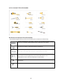
TOOLS NEEDED:
MATERIALS NEEDED:
(Additional materials may be required to comply with local codes)
Hot Water Supply Line - Minimum 3/4” O.D. copper tubing or metal braided
dishwasher supply line.
UL listed conduit connector or strain relief.
Shut-off valve and fittings appropriate for hot water supply line (copper
tubing/compression fitting, or braided hose).
Silicone Glue
Silicone Glue

6
MATERIALS SUPPLIED
PARTS SUPPLIED
The parts required for positioning the dishwasher are in plastic bags. Check that all of the
following parts are contained in the plastic bags.
DISHWASHER PARTS BAG 4
(MODEL
DEPENDING)
f. Toe Kick Bracket
g. Screws Ø 5/32” x 7/32” (Ø 4mm x 6mm)
h. Plinth Fixing Metal
j. Adjustable Plinth
k. Adjustable Plinth Metal (130mm)
l. Adjustable Plinth Metal (80mm)
m. Plinth Locking Pins
DISHWASHER
PARTS BAG 5
(MODEL
DEPENDING)
n. Long Legs
Screws Ø 5/32” x 19/32” (Ø 4mm x 15mm)
Mounting Bracket Left
Mounting Bracket Right
c.
d.
e.
DISHWASHER PARTS BAG 3
DISHWASHER PARTS BAG 2
b. Steam Protection Foil
MANUAL BAG
The
dishwasher comes with a manual bag
containing:
User manual, Installation manual
DISHWASHER
PARTS BAG 1
This
dishwasher bag comes with the following parts:
a. Hose Clamp

7
43.5
DISHWASHER SPECIFICATIONS
TECHNICAL FEATURES
Load Capacity
8 place settings
Permissible water pressure
4.35 - 145 psi (0.3 - 10 bars)
Electrical connection
120V (volts), 12A (amps), 60Hz (hertz)
Total power
1400 W (watts)
Heater power
1100 W (watts)
Notice:
Because we continually strive to improve our products, we may change our
specifications and design without prior notice.
This device corresponds to the following standards: UL 749
Household Dishwasher Standard.
( )
824 mm-874mm
(32 7/16"- 34 7/16")

8
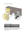
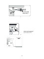
ENCLOSURE PREPARATION
ELECTRICAL PREPARATION WARNING
The dishwasher is designed for an electrical supply of 120V, 60Hz, AC, connected to a dishwasher-
dedicated, properly grounded electrical circuit with a fuse or breaker rated for 15 amperes.
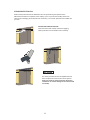
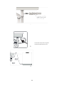
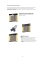
PREPARATION FOR INSTALLING MOUNTING BRACKETS
The mounting brackets in the plastic bag should be used when the dishwasher
is installed in the cabinetry. Use of any parts other than mounting brackets may result in damage to
property or bodily injury.
Place the two mounting brackets into the top corners of
the dishwasher.
If necessary (according to countertop board
material), bend the sides of mounting brackets.
If material of countertop
board is wooden etc.
If material of countertop
board is ceramic etc.;

9
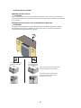
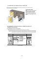
ADJUSTING HEIGHT
First Step: Before the dishwasher is placed in the cabinetry, the front feet are closed until the end and
the dishwasher is placed in the cabinetry.
Second Step: Adjust the forefoot level with a flat screwdriver to stabilize the dishwasher and raise it
to the enclosure height.
Third Step: Adjust the rear foot level with a Philips screwdriver to balance and raise the dishwasher to
the enclosure height.
- Make sure the dishwasher is plumb and notice dishwasher can be placed with a small clearance
under the countertop.
- For the front foot, turning the feet in the direction of the black arrows with the flat screwdriver allows
the dishwasher to move downwards.
- For the rear foot, Turning the Philips screwdriver in the direction of the black arrows will take
the dishwasher feet down.
If the height of the enclosure is 32 9/32" to 34 9/32" (820mm-870mm) use short supports as shown in
the figure.
If the height of the enclosure is above 32 9/32" (870mm) use long supports as shown in the figure.

10
WATER SUPPLY CONNECTION
Water supply may be connected to the dishwasher in one of two ways:
- With metal braided hose.
- With copper tubing BRAIDED
HOSE/COPPER TUBING
After connections are made turn on the water supply to check for leaks.
Hot water supply line: Use minimum 3/4” O.D. copper tubing or metal braided dishwasher supply line.
•
"Water Inlet valve of dishwasher has 3/4"-11.5NH inlet coupling thread dimension according to
ASME B1.20.7-1991.
•
When you are buying water inlet hose for your dishwasher, please choose the thread dimension of
the inlet hose as compatible with indicated water inlet valve inlet coupling thread dimension (3/4"-
11.5NH) of your dishwasher.
•
Temperatures required for soldering and sweating will damage the dishwasher’s water inlet valve so if
any such operation is needed, keep the heat source min. 77/8” (200mm) away from the dishwasher’s
water inlet valve.
•
There should not be any sharp bends in the water line that may restrict the water flow.
•
Teflon tape or pipe tread compound must be used for sealing the connection. Before connecting the
copper water supply line to the dishwasher, flush it with hot water to clear any foreign material.

11
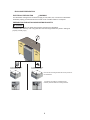
STEAM PROTECTION FOIL
Steam will be produced when the dishwasher door is opened during the operation of the
dishwasher and after the completion of the washing cycle. To prevent the resulting steam from
collecting and damaging the underside of the countertop, use a steam protection foil included with
your unit.
FITTING THE PROTECTION FOIL
Clean the surface with a damp cloth before applying
steam protection to the underside of the countertop.
The steam protection foil must be applied where the
steam escapes from when the door is first opened.
Failure to install the steam protection foil during
installation can lead to damage to the cabinets and
countertop.

12
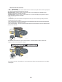
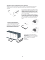
PLACEMENT OF DISHWASHER INTO THE OPENING
Now place the dishwasher into the opening and get ready to connect all the hoses and electrical
connections.
CAUTION
Make sure all hoses are pulled
through the side opening of the
cabinet, no hoses are kinked, and
all slack is taken out as shown in
the figure.
DRAIN HOSE CONNECTION, WATER SUPPLY & ELECTRICAL
CONNECTIONS
DRAIN HOSE CONNECTION
1. Check the parts on the sink to which the drain hose will be connected to.
2. There are several ways to insert the drain hose into the drain hose connector of the sink, as
shown in the following figures. You must connect the drain hose in accordance with the water pipe
installation regulations in your region.
Garbage Disposal With an air gap Without an air gap
Air gap
Hose
Clamp
Drain Hose
Hose clamp
A. Without disposal
647 mm-717 mm
820mm-870 mm
824 mm- 874 mm
(32 7/16"- 34 7/16")

13
Garbage disposal With an air gap Without an air gap
Air gap
Hose Clamp
Drain Hose
Hose clamp
B. With Garbage Disposal
3. Check the size of the sink’s drain hose connector. If needed, cut the drain hose so its end fits onto
the sink connector (5/8 in., 3/4 in., or 1 in. - as shown in C below). If the end of the drain hose does not
fit onto the drain hose connector of the sink, use an adaptor purchasable at a plumbing/hardware
supply store.
4. Slide a hose clamp over the end of the drain hose. Attach the drain hose to the sink connector,
slide the hose clamp to the end of the hose, and then tighten the hose clamp. NOTE: You must use
a hose clamp. Failure to do so may cause water leakage.
5. If there is no air gap, make sure to hang the middle of the drain hose well above the sink cabinet
base to prevent backflow (see Figure E below).
6. When drilling a hole for the drain hose on the cabinet wall, take caution not to damage the drain
hose with the sharp edges of the hole. On wooden walls, use sanding to soften the edges. On metal
walls, use insulation tape or duct tape to cover the sharp edges around the hole.
7. Take caution not to damage the drain hose when installing the dishwasher on the floor, wall, or
cabinet.
NOTE: To prevent leaks or drainage problems, make sure the drain hose is not damaged, kinked, or twisted.
8. Do not cut the wrinkled area of the drain hose to fit the size. When arranging the drain hose, take
caution not to contact on sharp edges of the cabinet or under-sink.
• Be careful when cutting off the end of the drain hose as there is a risk of injury.
Clean around the sink’s drain connection so that it does not damage the hose. Check for any foreign
items in the drain hose and remove them.
• When arranging the drain hose, make sure the drain hose is not cut, torn, or broken by any sharp
edges of the floor, the product itself, or the cabinet. A damaged drain hose causes a leak.

14
Use the hose clamp shown in Figure D.
for drain hose assembly to the sink.
D
E

15
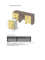
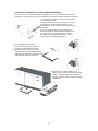
ADJUSTING THE MOVABLE TOE KICK (MODEL DEPENDING)
Now that you have successfully installed the dishwasher, you need to attach the toe kick to the
dishwasher. The two-piece toe kick can be adjusted to the height and depth needed for your kitchen.
A. If the height is 32 9/32" to 34 9/32" (820mm-870mm)
and uses short supports:
adjustable plinth metal with 80 mm length (v), toe kick
brackets(o) are installed. Mounting is done using
Screws Ø 5/32” x 7/32” (Ø 4mm x 6mm) with a Philips
Screwdriver.
B. A. If the height is above 34 9/32” (870mm) and
uses short supports; adjustable plinth metal with 130
mm length (v), toe kick brackets(o) are installed.
Mounting is done using Screws Ø 5/32” x 7/32” (Ø
4mm x 6mm) with a Philips Screwdriver.
C. The adjustable plinth number is
determined according to the required
distance and assembled to each other.
D. As shown in the image to the right, the
cylindrical feet of the adjustable plinth are
attached to the plinth fixing metal parts and
shifted through the cavity of the part.
870x1
880x2
890x3
900x4
910x5/6
r s
870x1
880x2
890x3
900x4
910x5/6
s
E. Depending on the desired depth, plinth
locking(y) is attached to the toe kick bracket(o).
F. Finally, Toe kick brackets(o) are attached to
the gaps under the machine and the installation
is completed.
o
1.
p
t

16
INSTALLER CHECKLIST
Your installer must have completed the following:
The dishwasher is square in the cabinetry and leveled.
The dishwasher is fastened securely to the cabinetry.
The dishwasher door opens and closes freely. The dishwasher door must close without hitting any cabinetry
or countertop.
The inlet water supply is turned on and checked for leaks.
The drain hose has been connected and checked for leaks. There must be no kinks or obstructions in the
drain hose.
The drain hose must be installed with a 28" (710mm) high drain loop for drain hook-ups without any air
removed.
If the dishwasher drain is hooked up to a garbage disposal, the drain hopper plug must be removed.
The spray arms are free and rotate freely. The rinse cycle has been run.
The water level will be below the filter screen after the end of the wash program.
It is normal to find some water in the drain filter area.
Set the water softener to the correct water hardness for your area. If the dishwasher drain is connected to a
garbage disposal, make sure that the drain/hopper plug has been removed.
FINAL INSTRUCTIONS
1. Press the On/Off button to turn the dishwasher on.
2. Power indicator light comes on.
3. Use the Program Select button to choose a washing program.
4. Start the program with the Start/Pause/Cancel button.
5. Run the dishwasher through one complete cycle. When the wash cycle is completed, use the On/Off button to
turn the dishwasher off.
SELF-HELP HINTS:
If the screen does not come on:
Check to make sure the breaker to the dishwasher is in the on position.
Check to make sure that the Supply cord is plugged.
If no water is coming into the dishwasher: Check to make sure the hot water shut-off is in the ON position.
If the water does not drain:
Make sure the drain hose is not kinked or comes out of the air gap next to the sink. Remove the drain hose from
the disposal and make sure the plug is removed.
NOTICE:
If your dishwasher is not operating properly after following these steps: Contact your dealer to schedule
an authorized service agent to inspect your new dishwasher for any function-related failure.
The manufacturer warranty does not cover installation, conversion, or customer education service visits.
You will find the model and serial number information on the label located on the right-hand side of the
inner door of your dishwasher, as shown above.
NOTICE:
Please make a copy of your invoice and keep it with this manual and register your dishwasher.
NOTICE:
If the dishwasher does not operate properly, refer to the self-help hints.

17
AVERTISSEMENT ATTENTION
INTRODUCTION
Lors de l’utilisation du lave-vaisselle, suivez attentivement les précautions évoquées dans le
présent manuel, en particulier les consignes de sécurité. Elles sont destinées à vous
faire gagner du temps et à ménager vos efforts lors de l’installation et vous aideront à
assurer le bon fonctionnement de votre lave- vaisselle. Veillez à respecter tous les
avertissements et mises en garde indiqués. Faites particulièrement attention aux icônes
avec des points d’exclamation. L’icône d’information fournira également des références
importantes.
AVERTISSEMENT :
Indique une situation potentiell ement dangereuse qui, si elle n’est pas évitée, pourrait
entraîner la mort ou des blessures graves.
ATTENTION :
Indique une situation potentiellement dangereuse qui, si elle n’est pas évitée, peut
entraîner des blessures. Cette icône peut également être utilisée pour signaler des
pratiques dangereuses.
Instructions :
Indique une situation potentiellement dangereuse qui, si elle n’est pas évitée, peut
endommager le lave- vaisselle, la vaisselle, l’équipement ou l’environnement.
1.
CONSIGNES DE SÉCURITÉ IMPORTANTES
En plus de ces instructions, le lave- vaisselle doit être installé:
* Conformément aux codes locaux ou, en l’absence de codes locaux,
* Aux États - Unis, conformément au Code national de l’électricité,
* Au Canada, conformément au Code canadien de l’éle ctricité C22.1 - dernière
édition/Codes provinciaux et municipaux et/ou codes locaux.
Instructions
Lisez attentivement les présentes instructions d’installation avant de procéder à
l’installation et suivez -les attentivement. Conservez les présentes instructions
d’installation et transmettez -les à tout futur utilisateur.
AVERTISSEMENT
Lors de l’installation du lave-vaisselle, suivez les précautions de base, y compris les
suivantes:
Instructions

18
Instructions
•Seul un technicien autorisé pour convertir ce lave-vaisselle raccordé par un cordon
d’alimentation en un lave-vaisselle raccordé de façon permanente. (Au besoin,
communiquez avec votre revendeur pour obtenir les coordonnées d’un service
après-vente autorisé pour la conversion à l’aide d’une trousse de conversion
appropriée)
•L’installation et les réparations doivent être effectuées par un installateur qualifié. Les
travaux effectués par des personnes non qualifiées peuvent être dangereux et
peuvent annuler la garantie.
Le lave-vaisselle doit être installé par un plombier, un entrepreneur ou un installateur
qualifié. L’installation effectuée par des personnes autres que celles mentionnées
dessus peut entraîner une installation incorrecte et des dommages matériels.
•Ne faites jamais fonctionner l’appareil s’il est endommagé, défectueux, partiellement
démonté ou s’il contient des pièces cassées ou manquantes.
•Respectez également les consignes de sécurité du manuel d’utilisation.
Pour réduire les risques de choc électrique, d’incendie ou de blessures, l’installateur
doit s’assurer que le lave-vaisselle est complètement hermétique au moment de
l’installation.
•Ne branchez le lave-vaisselle à l’alimentation électrique que lorsque tous les travaux
d’installation et de plomberie sont terminés.
•Si le lave-vaisselle est installé dans un endroit où il fait très froid (p. ex. dans une
maison de vacances, une cabane, etc.), vous devez vidanger toute l’eau de l’intérieur
du lave-vaisselle. Les ruptures du réseau d’eau causées par le gel ne sont pas
couvertes par la garantie.
•Le lave-vaisselle doit être fixé aux meubles adjacents à l’aide des supports fournis.
Le non-respect de cette consigne peut entraîner des dommages matériels ou
corporels
Raccordez le lave-vaisselle à un circuit d’alimentation électrique correctement
protégé et dimensionné et aux valeurs nominales appropriées pour éviter toute
surcharge électrique. Le lave-vaisselle est conçu pour une alimentation électrique de
120 V (volts), 60 Hz (hertz), CA, branché à un circuit électrique indépendant,
correctement mis à la terre avec un fusible ou des disjoncteurs prévus pour
ampères. Les conducteurs d’alimentation électrique doivent être d’un calibre
minimum de fil de cuivre no16 AWG pour un minimum de 75 °C (167 °F). Ces
exigences doivent être respectées pour éviter les blessures et les dommages à la
machine. Consultez un électricien qualifié en cas de doute.
•N’utilisez jamais de rallonge ou de prise de courant portative pour brancher le
lave-vaisselle à une source d’alimentation électrique.
•Assurez-vous que tous les emballages et sachets en plastique et autres petites
pièces, etc. sont jetés de façon sûre et maintenez-les hors de la portée des enfants.
Risque de suffocation!

19
Instructions
•Retirez la porte du compartiment de lavage lorsque vous mettez un vieux
lave-vaisselle hors service ou que vous le jetez. Veillez à ce que l’appareil ne présente
aucun danger pour les enfants lors de son stockage en vue de son élimination.
•Les anciens appareils électroménagers peuvent contenir des matériaux qui peuvent
être recyclés. Veuillez contacter votre autorité de recyclage locale pour connaître les
possibilités de recyclage de ces matériaux.
Le tuyau de vidange du lave-vaisselle doit être installé à une hauteur de vidange d’au
moins 28 po (710 mm) par rapport au bas du meuble, sinon l’eau risquerait de ne pas
s’évacuer correctement du lave-vaisselle.
•Ce lave-vaisselle est destiné à un usage résidentiel exclusivement et ne doit pas être
utilisé dans des établissements commerciaux.
•Nouvelle installation - Si le lave-vaisselle est une nouvelle installation, la majeure
partie du travail doit être effectuée avant que le lave-vaisselle ne soit mis en place.
•Remplacement - Si le lave-vaisselle est destiné à remplacer un autre lave-vaisselle,
vérifiez la compatibilité des raccords existants avec ceux du nouveau lave-vaisselle et
remplacez les pièces au besoin.

35
Clé à pipe
Pince coupante
Perceuse
Scie cloche
Marteau
Pince à dénuder
Mètre à ruban
Tournevis Torx
Tournevis cruciforme
Clé à molette
Tournevis plat
Les Ciseaux
Niveaux
Brosse
Crayon
OUTILS POUVANT ÊTRE NÉCESSAIRES
MATÉRIAUX QUI PEUVENT ÊTRE NÉCESSAIRES
(Des matériaux supplémentaires peuvent être nécessaires pour se conformer aux codes locaux)
Conduite d'alimentation en eau chaude - Tubes en cuivre de diamètre extérieur minimum
de 3/4 po ou canalisation d'alimentation tressée en métal pour lave-vaisselle.
Connecteur de conduit ou décharge de traction homologué UL.
Vanne d'arrêt et raccords appropriés pour la conduite d'alimentation en eau
chaude (tube en cuivre / raccord à compression ou tuyau tressé).
Colle silicone
Colle silicone
La page est en cours de chargement...
La page est en cours de chargement...
La page est en cours de chargement...
La page est en cours de chargement...
La page est en cours de chargement...
La page est en cours de chargement...
La page est en cours de chargement...
La page est en cours de chargement...
La page est en cours de chargement...
La page est en cours de chargement...
La page est en cours de chargement...
La page est en cours de chargement...
La page est en cours de chargement...
-
 1
1
-
 2
2
-
 3
3
-
 4
4
-
 5
5
-
 6
6
-
 7
7
-
 8
8
-
 9
9
-
 10
10
-
 11
11
-
 12
12
-
 13
13
-
 14
14
-
 15
15
-
 16
16
-
 17
17
-
 18
18
-
 19
19
-
 20
20
-
 21
21
-
 22
22
-
 23
23
-
 24
24
-
 25
25
-
 26
26
-
 27
27
-
 28
28
-
 29
29
-
 30
30
-
 31
31
-
 32
32
-
 33
33


Summit DW186NTADA Le manuel du propriétaire
- Taper
- Le manuel du propriétaire
- Ce manuel convient également à
dans d''autres langues
- English: Summit DW186NTADA Owner's manual
Autres documents
-
Bertazzoni DW24S3IPV Manuel utilisateur
-
-
Bertazzoni DW24T3IPV Manuel utilisateur
-
Heartland AMCTTDW-MBL Le manuel du propriétaire
-
AGA marvel AELTTDW Guide d'installation
-
Gaggenau SGE53B55UC/13 Guide d'installation
-
Yes SPX68B55UC Guide d'installation
-
Yes SPE53B55UC/04 Guide d'installation
-
Bosch SGE53B56UC Guide d'installation
-
Gaggenau DF480763F Guide d'installation