
Gas Dryer Installation Instructions
Canadian Electric Dryer Installation Instructions
Instructions pour l'installation de la s6cheuse h gaz
p
(E.-U. et Canada) et 61ectrique (Canada uniquement)
Table of Contents
DRYER SAFETY ................................................................ 2
INSTALLATION REQUIREMENTS .................................... 4
Tools and Parts .................................................................... 4
LOCATION REQUIREMENTS ..................................................... 5
ELECTRIC DRYER POWER HOOKUP-CANADA ONLY ........... 6
GAS DRYER POWER HOOKUP ................................................. 7
INSTALL LEVELING LEGS .......................................................... 9
MAKE GAS CONNECTION ......................................................... 9
VENTING .................................................................................... 10
Venting Requirements ....................................................... 10
Plan Vent System ............................................................... 11
Install Vent System ............................................................ 12
CONNECT INLET HOSES ......................................................... 12
CONNECT VENT ....................................................................... 14
LEVEL DRYER ........................................................................... 14
COMPLETE INSTALLATION CHECKLIST ............................... 15
REVERSE DOOR SWING .......................................................... 15
Table des matibres
SF:CURITE DE LA S¢:CHEUSE ........................................ 17
EXIGENCES D'INSTALLATION ....................................... 19
Outillage et pi_ces ............................................................. 19
EXIGENCES D'EMPLACEMENT ............................................... 20
RACCORDEMENT DE LA SECHEUSE
leLECTRIQUE - CANADA SEULEMENT ................................... 21
RACCORDEMENT ELECTRIQUE DE LA SECHEUSE
A GAZ .......................................................................................... 22
iNSTALLATiON DES PIEDS DE NIVELLEMENT ...................... 23
RACCORDEMENT AU GAZ ....................................................... 25
UEVACUATION ........................................................................... 25
Exigences concernant I'evacuation ................................. 25
Planification des circuits de conduits .............................. 26
installation du syst_me d'6vacuation ............................... 28
RACCORDEMENT DES TUYAUX DE VIDANGE ...................... 28
RACCORDEMENT DU SYSTl=ME DqeVACUATION ................. 30
leTABLIR L'APLOMB DE LA SLeCHEUSE .................................. 30
ACHEVER L'INSTALLATION LISTE DE VLeRIFICATION .......... 31
iNVERSiON DU SENS D'OUVERTURE DE LA PORTE ............ 31
Para obtener acceso al "lnstrucciones de instalaci6n" en espaSol, o para obtener informaci6n
adicional acerca de su producto, visite: www.whirlpool.com
Tenga listo su nOmero de modelo completo. Puede encontrar el nOmero de modelo
y de serie dentro de la cavidad superior de la puerta.
iNSTALLATiON NOTES
Date of purchase:
Date of installation:
Installer:
Model number:
Serial number:
NOTES CONCERNANT L'INSTALLATION
Date d'achat :
Date d'installation :
Installateur :
Num6ro de module :
Num6ro de s6rie :
W10562336B
W10562340B=SP

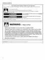
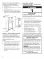
DRYER SAFETY
Your safety and the safety of others are very important.
We have provided many important safety messages in this manual and on your appliance. Always read and obey all safety
messages.
This is the safety alert symbol.
This symbol alerts you to potential hazards that can kill or hurt you and others.
All safety messages will follow the safety alert symbol and either the word "DANGER" or "WARNING."
These words mean:
You can be killed or seriously injured if you don't immediately
follow instructions.
You can be killed or seriously injured if you don't follow
instructions.
All safety messages will tell you what the potential hazard is, tell you how to reduce the chance of injury, and tell you what can
happen if the instructions are not followed.
WARNING - ...i.kofFi,o..
- Clothes dryer installation must be performed by a qualified installer.
- Install the clothes dryer according to the manufacturer's instructions and local codes.
- Do not install a clothes dryer with flexible plastic venting materials or flexible metal
(foil type) duct. if flexible metal duct is installed, it must be of a specific type identified
by the appliance manufacturer as suitable for use with clothes dryers, Flexible venting
materials are known to collapse, be easily crushed, and trap lint. These conditions will
obstruct clothes dryer airflow and increase the risk of fire,
= To reduce the risk of severe injury or death, follow all installation instructions.
- Save these instructions.
IMPORTANT: When discarding or storing your old clothes dryer, remove the door. i
2

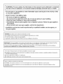
WARNING: For your safety, the information in this manual must be followed to minimize 1
the risk of fire or explosion, or to prevent property damage, personal injury, or death, j
- Do not store or use gasoline or other flammable vapors and liquids in the vicinity of this
or any other appliance.
- WHAT TO DO iF YOU SMELL GAS:
= Do not try to light any appliance.
®Do not touch any eJectrical switch; do not use any phone in your building.
®Clear the room, building, or area of all occupants.
• Immediately carl your gas supplier from a neighbor's phone. Follow the gas supplier's
instructions.
• if you cannot reach your gas supplier, carl the fire department.
- Installation and service must be performed by a qualified installer, service agency, or
the gas supplier.
WARNING: Gas leaks cannot always be detected by smell.
Gas suppliers recommend that you use a gas detector approved by UL or CSA.
For more information, contact your gas supplier.
If a gas leak is detected, follow the "What to do if you smell gas" instructions.
iMPORTANT: The gas installation must conform with local codes, or in the absence of local codes, with the National Fuel Gas
Code, ANSi Z223.1/NFPA 54 or the Canadian Natural Gas and Propane Installation Code, CSA B149.1.
The dryer must be electrically grounded in accordance with local codes, or in the absence of local codes, with the National
Electrical Code, ANSIiNFPA 70 or Canadian Electrical Code, CSA C22.1.
In the State of Massachusetts, the following installation instructions apply:
[] Installations and repairs must be performed by a qualified or licensed contractor, plumber, or gasfitter qualified or licensed by
the State of Massachusetts.
[] if using a ball valve, it shall be a T=handle type.
[] A flexible gas connector, when used, must not exceed 3 feet.
State of California Proposition 65 Warnings:
WARNING: This product contains one or more chemicals known to the State of California to cause cancer.
WARNING: This product contains one or more chemicals known to the State of California to cause birth defects or other
reproductive harm.

INSTALLATION REQUIREMENTS
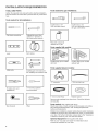
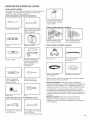
TOOLS AND PARTS
Gather the required tools and parts before starting installation.
Read and follow the instructions provided with any tools listed
here.
Tools needed for all installations:
Tools needed for gas installations:
Flat-blade screwdriver
Level
Utility knife
Adjustable wrench that
opens to 1" (25 mm) or
hex-head socket wrench
Vent clamps
Caulking gun and compound
(for installing new exhaust vent)
8" (203 mm) or 10"
(254 mm) pipe wrench
8" (203 mm) or 10"
(254 mm) adjustable wrench
(for gas connections)
Pipe-joint compound
resistant to LP gas
Parts supplied {all models):
Leveling legs (4) for models
with riser
Leveling legs (4) for models
without riser
Parts supplied {steam models):
&
"Y" connector
2' (0.6 m) inlet hose
Tin snips (new vent
installations)
Tape measure
1/4"( 6 mm) nut driver
(recommended)
Pliers
5' (1.52 m) Net Hose Rubber washer
Remove parts package from dryer drum. Check that all parts
are included.
Parts needed: (Not supplied with dryer)
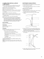
Check local codes. Check existing electrical supply and venting.
See "Electrical Requirements" and "Venting Requirements"
before purchasing parts.
Mobile home installations require metal exhaust system hardware
available for purchase from the dealer from whom you purchased
your dryer. For further information, please refer to the "Assistance
or Service" section in your "Use and Care Guide."
Optional Equipment: (Not supplied with dryer)
Refer to your "Use and Care Guide" for information about
accessories available for your dryer.
4

LOCATION REQUIREMENTS
Explosion Hazard
Keep flammable materials and vapors, such as
gasoline, away from dryer.
Place dryer at least 18 inches (460 ram) above the floor
for a garage installation.
Failure to do so can result in death, explosion, or fire.
You will need:
[] A location allowing for proper exhaust installation.
See "Venting Requirements."
[] A separate 15 or 20-amp circuit needed for gas dryers and
30-amp circuit needed for electric dryers.
[] If using power supply cord, a grounded electrical outlet
located within 2 ft. (610 mm) of either side of dryer.
See "Electrical Requirements."
[] Floor must support dryer weight of 200 Ibs. (90.7 kg).
Also consider weight of companion appliance.
[] Level floor with maximum slope of 1" (25 mm) under entire
dryer. If slope is greater than 1" (25 mm), clothes may not
tumble properly and automatic sensor cycles may not
operate correctly.
[] For garage installation, place dryer at least 18" (460 mm)
above floor.
[] Steam models only: Cold water faucets located within 4 ft.
(1.2 m) of the water fill valves, and water pressure of 20-100
psi (137.9-689.6 kPa). You may use the water supply for your
washer using the "Y" connector provided.
Do not operate your dryer at temperatures below 45° F (7°C). At
lower temperatures, the dryer might not shut off at the end of an
automatic sensor cycle, this can result in longer drying times.
The dryer must not be installed or stored in an area where it will
be exposed to water and/or weather.
Check codes requirements. Some codes limit, or do not permit,
installation of the dryer in garages, closets, mobile homes, or
sleeping quarters. Contact your local building inspector.
NOTE: No other fuel-burning appliance can be installed in the
same closet as a dryer.
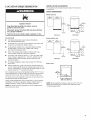
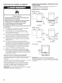
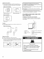
INSTALLATION CLEARANCES
The location must be large enough to allow the dryer door
to open fully.
DRYER DiMENSiONS
-<_ 22t/4.-_
(565 ram}
Models with riser
30"-_
(783 ram)/- --
J
--...._d
Side view
T
441/2"
(1t30 ram)
1/2"
(!3 turn)
63/4.
(!71¢m]
4"
(162 ram}
53/8" I
--_( )-- (26++
rNm)
(279 ram)
Back view
Models without riser
(565 turn)
< 30"_
(783 ram} _"
Side view
42_ "
(1080 mm)
+
13/8"
(35 ram)
43/4"
(121mm)
2"
(51 rnm)
33/8" I
__
{368 )_,_! 11" "_-(25ram)
(279 rnm}
Back view
Bottom view:
31/4"
(83_m)
_-141/2"-_ "_-141/2"-_
(368 ram) (368 ram)
NOTE: Most installations require a minimum of 5" (127 mm)
clearance behind dryer for exhaust vent with elbow. See
"Venting Requirements."

Spacingfor recessedareaor closet installation
All dimensions show recommended spacing allowed, with tested
spacing of 0" (0 mm) clearance on sides and rear.
[] Additional spacing should be considered for ease of
installation and servicing.
[] Additional clearances might be required for wall, door, and
floor moldings.
[] Additional spacing should be considered on all sides of the
dryer to reduce noise transfer.
[] For closet installation, with a door, minimum ventilation
openings in the top and bottom of the door are required.
Louvered doors with equivalent ventilitation openings are
acceptable.
[] Companion appliance spacing should also be considered.
g
(76
g
(76
{127 rnm)
(25 rnm)
Mobile home - Additional installation requirements:
This dryer is suitable for mobile home installations.
The installation must conform to the Manufactured
Home Construction and Safety Standard, Title 24 CFR,
Part 3280 (formerly the Federal Standard for Mobile home
construction and Safety, Title 24, HUD Part 280) or Standard
CAN/CSA-Z240 MH.
Mobile home installations require:
All dryers:
[] Metal exhaust system hardware, available for purchase
from your dealer. For further information, see "Assistance
or Service" section in your "Use and Care Guide."
[] Special provisions must be made in mobile homes to
introduce outside air into dryer. Openings (such as a
nearby window) should be at least twice as large as
dryer exhaust opening.
For gas dryers mobile home installations:
[] Mobile Home Installation Hold-down Kit Part Number
W10432680 is available to order. For further information,
see "Assistance or Service" section in your "Use and
Care Guide."
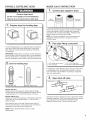
ELECTRIC DRYER
POWER HOOKUP- CANADA ONLY
ELECTRICAL REQUIREMENTS
Electrical Shock Hazard
Plug into a grounded 4 prong outlet.
Failure to do so can result in death or electrical shock.
it is your responsibility:
[] Tocontact a qualified electrical installer.
[]
To be sure that the electrical connection is adequate and in
conformance with Canadian Electrical Code, C22.1-1atest
edition and all local codes. A copy of above codes standard
may be obtained from: Canadian Standards Association,
178 Rexdale Blvd., Toronto, ON M9W 1R3 CANADA.
[]
To supply the required 4 wire, single phase, 120/240 volt,
60 Hz, AC only electrical supply on a separate 30-amp
circuit, fused on both sides of the line. A time-delay fuse or
circuit breaker is recommended. Connect to an individual
branch circuit.
[] This dryer is equipped with a CSA
International Certified Power Cord
intended to be plugged into a standard
14-30R wall receptacle. The cord is
5 ft. (1.52 m) long. Be sure wall receptacle 4-wire receptacle
is within reach of dryer's final location. (14-30R)
If using a replacement power supply cord, it is recommended that
you use Power Supply Cord Replacement Part Number 9831317.
For further information, please reference service numbers located
in "Assistance or Service" section of your "Use and Care Guide."
GROUNDING INSTRUCTIONS
[] For a grounded, cord-connected dryer:
This dryer must be grounded, in the event of malfunction or
breakdown, grounding will reduce the risk of electric shock
by providing a path of least resistance for electric current.
This dryer is equipped with a cord having an equipment-
grounding conductor and a grounding plug. The plug must
be plugged into an appropriate outlet that is properly
installed and grounded in accordance with all local codes
and ordinances.
WARNING: Improper connection of the equipment-
grounding conductor can result in a risk of electric shock.
Check with a qualified electrician or service representative
or personnel if you are in doubt as to whether the dryer is
properly grounded. Do not modify the plug provided with
the dryer: if it will not fit the outlet, have a proper outlet
installed by a qualified electrician.
SAVE THESE INSTRUCTIONS
6

GAS DRYER POWER HOOKUP
ELECTRICAL REQUIREMENTS
Electrical Shock Hazard
Plug into a grounded 3 prong outlet.
Do not remove ground prong.
Do not use an adapter.
Do not use an extension cord.
Failure to follow these instructions can result in death,
fire, or electrical shock.
[]
120 Volt, 60 Hz, AC only, 15- or 20- amp fused electrical
supply is required. A time-delay fuse or circuit breaker is
recommended, it is also recommended that a separate
circuit serving only this dryer be provided.
GROUNDING INSTRUCTIONS
m For a grounded, cord-connected dryer:
This dryer must be grounded, in the event of malfunction or
breakdown, grounding will reduce the risk of electric shock
by providing a path of least resistance for electric current.
This dryer is equipped with a cord having an equipment-
grounding conductor and a grounding plug. The plug must
be plugged into an appropriate outlet that is properly
installed and grounded in accordance with all local codes
and ordinances.
WARNING: Improper connection of the equipment-
grounding conductor can result in a risk of electric shock.
Check with a qualified electrician or service representative
or personnel if you are in doubt as to whether the dryer is
properly grounded. Do not modify the plug provided with
the dryer: if it will not fit the outlet, have a proper outlet
installed by a qualified electrician.
SAVE THESE INSTRUCTIONS
GAS SUPPLY REQUIREMENTS
Explosion Hazard
Use a new CSA International approved gas supply line.
Install a shut-off valve.
Securely tighten all gas connections.
if connected to LP, have a qualified person make sure
gas pressure does not exceed 13" (330 ram) water
column.
Examples of a qualified person include:
licensed heating personnel,
authorized gas company personnel, and
authorized service personnel.
Failure to do so can result in death, explosion, or fire.
GAS TYPE
Natural Gas:
This dryer is equipped for use with Natural gas. It is design-
certified by CSA International for LP (propane or butane) gases
with appropriate conversion.
[] Your dryer must have the correct burner for the type of gas
in your home. Burner information is located on the rating
plate in the door well of your dryer. If this information does
not agree with the type of gas available, contact your dealer
or call the phone numbers referenced in the "Assistance or
Service" section of your "Use and Care Guide."

LP Gas Conversion:
IMPORTANT: Conversion must be made by a qualified
technician.
No attempt shall be made to convert the dryer from the gas
specified on the model/serial rating plate for use with a different
gas without consulting your gas company.
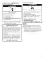
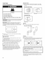
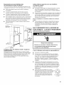
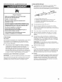
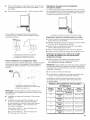
GAS SUPPLY LiNE
[] Must include 1/8" NPT minimum plugged tapping accessible
for test gauge connection, immediately upstream of the gas
connection to the dryer.
E
B
A. 3/8" flexible gas connector
B. 3/8" pipe to flare adapter fitting
C. 1/8" NPT minimum plugged tapping
D. 1/2" NPT gas supply line
E. Gas shutoff valve.
[] 1/2" IPS pipe is recommended.
[] 3/8" approved aluminum or copper tubing is acceptable for
lengths under 20 ft. (6.1 m) if local codes and gas supplier
permit.
[] If you are using Natural gas, do not use copper tubing.
[] Lengths over 20 ft. (6.1 m) should use larger tubing and
a different size adapter fitting.
[] If your dryer has been converted to use LP gas, 3/8" LP
compatible copper tubing can be used. If the total length of
the supply line is more than 20 ft. (6.1 m), use larger pipe.
NOTE: Pipe-joint compounds that resist the action of LP gas
must be used. Do not use TEFLON<ettape.
[] Must include shut-off valve
in the U.S.A.:
An individual manual shut-off valve must be installed within
six (6) ft. (1.8 m) of the dryer in accordance with the National
Fuel Gas Code, ANSi Z223.1. The location should be easy to
reach for opening and closing.
in Canada:
An individual manual shut-off valve must be installed in
accordance with the B149.1, Natural Gas and Propane
installation Code. It is recommended that an individual
manual shutoff valve be installed within six (6) ft. (1.8 m) of
the dryer. The location should be easy to reach for opening
and closing.
GAS SUPPLY CONNECTION REQUIREMENTS
[] Use an elbow and a 3/8" flare x 3/8" NPT adapter fitting
between the flexible gas connector and the dryer gas pipe,
as needed to avoid kinking.
[] Use only pipe-joint compound. Do not use TEFLON _'*_ttape.
[] This dryer must be connected to the gas supply line with a
listed flexible gas connector that complies with the standard
for connectors for gas appliances, ANSI Z21.24 or CSA 6.10.
BURNER INPUT REQUIREMENTS
Elevations above 10,000 ft. (3,048 m}:
[] When installed above 10,000 ft. (3,048 m) a 4% reduction
of the burner Btu rating shown on the model/serial number
plate is required for each 1,000 ft. (305 m) increase in
elevation.
Gas supply pressure testing
[] The dryer must be disconnected from the gas supply piping
system during pressure testing at pressures greater than
1/2 psi.
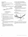
DRYER GAS PIPE
[] The gas pipe that comes out through the rear of your dryer
has a 3/8" male pipe thread.
4 4"
(102 rnrn)
A. 1/2" NPT gas supply line
B. 3/8" NPT dryer pipe
NOTE: If the dryer is mounted on a pedestal, the gas pipe height
must be an additional 10" (254 mm) or 15.5" (394 mm) from the
floor, depending on the pedestal model. For a garage installation,
the gas pipe height must be an additional 18" (460 mm) from
the floor.
1®TEFLON is a registered trademark of E.I. Dupont De Nemours and Company.
8

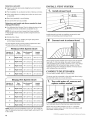
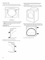
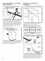
INSTALL LEVELING LEGS
Excessive Weight Hazard
Use two or more people to move and install dryer.
Failure to do so can result in back or other injury.
_, Prepare dryer for ievelin 9 legs
To avoid damaging floor, use a large flat piece of cardboard
from dryer carton; place under entire dryer. Firmly grasp
dryer body (not console panel) and gently lay dryer down
on cardboard.
IMPORTANT." If laying dryer on its back, use the cardboard
corner posts the dryer was packed with to avoid damaging
the back of the dryer. Lay the dryer on its side if you do not
have the cardboard corner posts the dryer was packed with.
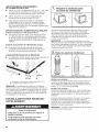
2, Screw in leveling
.J
..........Flange
Models with riser
legs
i
Models with riser:
Using a wrench, screw legs into cabinet until foot flange
touches the riser. Foot is fully installed when bottom of foot
is approximately 1/2" (13 mm) from bottom of the riser.
Models without riser:
Using a wrench and tape measure, screw legs into leg holes
until bottom of foot is approximately 13/8'' (35 mm) from
bottom of dryer.
Now stand the dryer on its legs. Slide the dryer until it is
close to its final location. Leave enough room for electrical
connection and to connect the exhaust vent.
NOTE: Refer to Dryer Dimensions in the Location
Requirements.
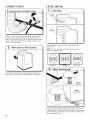
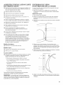
MAKE GAS CONNECTION
"1, Connect gas supply to dryer
Flared
male fitting
Non-flared
male fitting
Remove red cap from gas pipe. Using a wrench to tighten,
connect gas supply to dryer. Use pipe-joint compound
on threads of all non-flared male fittings. If flexible metal
tubing is used, be sure there are no kinks.
NOTE: For LP gas connections, you must use pipe-joint
compound resistant to action of LP gas. Do not use
TEFLON _*>ttape.
2, Plan pipe fitting connection
I
A combination of pipe fittings must be used to connect dryer
to existing gas line. A recommended connection is shown.
Your connection may be different, according to supply line
type, size, and location.
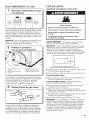
3. Open shut-off valve
Closed_
Open valve
Open shut-off valve in supply line; valve is open when handle
is parallel to gas pipe. Then, test all connections by brushing
on an approved noncorrosive leak-detection solution.
Bubbles will show a leak. Correct any leaks found.

VENTING
VENTING REQUIREMENTS
Fire Hazard
Use a heavy metal vent,
Do not use a plastic vent.
Do not use a metal foil vent,
Failure to follow these instructions can result in death
or fire.
WARNING: To reduce the risk of fire, this dryer MUST BE
EXHAUSTED OUTDOORS.
iMPORTANT: Observe all governing codes and ordinances.
Dryer exhaust must not be connected into any gas vent,
chimney, wall, ceiling, attic, crawlspace, or a concealed space
of a building. Only rigid or flexible metal vent shall be used for
exhausting.
4"
(102 ram)
f
4" (102 ram) heavy metal exhaust vent
[] Only a 4" (102 mm) heavy metal exhaust vent and clamps
may be used.
[] Do not use plastic or metal foil vent.
Rigid metal vent:
[] Recommended for best drying performance and to avoid
crushing and kinking.
Flexible metal vent: (Acceptable only if accessible to clean)
[] Must be fully extended and supported in final dryer location.
[] Remove excess to avoid sagging and kinking that may
result in reduced airflow and poor performance.
[] Do not install in enclosed walls, ceilings, or floors.
[] The total length should not exceed 73/4ft. (2.4 m).
NOTE: If using an existing vent system, clean lint from
entire length of the system and make sure exhaust hood
is not plugged with lint. Replace plastic or metal foil vents
with rigid metal or flexible metal vents. Review Vent System
Chart and if necessary, modify existing vent system to
achieve best drying performance.
Exhaust hoods:
[] Must be at least 12" (305 mm) from ground or any object
that may obstruct exhaust (such as flowers, rocks, bushes,
or snow).
Recommended Styles:
Louvered Hood
Acceptable Style:
Angled Hood
Elbows:
Box Hood
[] 45° elbows provide better airflow than 90° elbows.
Recommended Styles:
Clamps:
[]
[]
Be
Use clamps to seal all joints.
Exhaust vent must not be connected or secured with screws
or other fastening devices that extend into interior of duct
and catch lint. Do not use duct tape.
Improper venting can cause moisture and lint to collect
indoors, which may result in:
[] Moisture damage to woodwork, furniture, paint, wallpaper,
carpets, etc.
[] Housecleaning problems and health problems.
Vent products can be purchased from your dealer. For more
information, see "Assistance or Service" section in your "Use
and Care Guide."
10

PLAN VENT SYSTEM
Recommended exhaust installations
Typical installations vent the dryer from the rear of the dryer.
Other installations are possible.
A ...........................
B
C
..............F
.... e
.............g
H
A. Dryer
B. Elbow
C. Wall
D. Exhaust hood
E. Clamps
R Rigid metal or flexible metal vent
G. Vent length necessary to connect elbows
H. Exhaust outlet
If you prefer, dryer may be converted to exhaust through
the bottom. You must contact your local dealer to have dryer
converted.
A B
A. Standard rear offset exhaust installation
B. Bottom exhaust installation
Alternate installations for close clearances
Venting systems come in many varieties. Select the type best
for your installation. Two close-clearance installations are shown.
Refer to the manufacturer's instructions.
Optional exhaust installations:
Fire Hazard
Use a heavy metal vent.
Do not use a plastic vent,
Do not use a metal foil vent.
Failure to follow these instructions can result in death
or fire.
[] Exhaust Cover Kit (to cover unused exhaust holes):
Part Number W10186596 - all models
[] Bottom Exhaust Kit- Part Number 8212503
A B
A. Over-the-top installation
(also available with one offset elbow)
B. Periscope installation
NOTE: The following kits for close clearance alternate
installations are available for purchase. Contact your local dealer.
[] Over-the-Top Installation:
Part Number 4396028
[]
Periscope installation (For use with dryer vent to wall vent
mismatch):
Part Number 4396037 - 0" (0 mm) to 18" (460 mm) mismatch
Part Number 4396011 - 18" (460 mm) to 29" (737 mm)
mismatch
Part Number 4396014 - 29" (737 mm) to 50" (1270 mm)
mismatch
Special provisions for mobile homes:
Exhaust vent must be securely fastened to a noncombustible
portion of mobile home and must not terminate beneath the
mobile home. Terminate exhaust vent outside.
Mobile Home Exhaust installation
11

Determine vent path:
[] Select route that will provide straightest and most direct
path outdoors.
[] Plan installation to use fewest number of elbows and turns.
[] When using elbows or making turns, allow as much room
as possible.
[] Bend vent gradually to avoid kinking.
[] Use as few 90° turns as possible.
Determine vent length and elbows needed for best
drying performance:
[] Use following Vent System Chart to determine type of vent
material and hood combinations acceptable to use.
NOTE: Do not use vent runs longer than those specified
in Vent System Chart. Exhaust systems longer than those
specified will:
[] Shorten life of dryer.
[] Reduce performance, resulting in longer drying times
and increased energy usage.
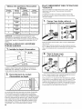
The Vent System Charts provide venting requirements that
will help achieve best drying performance.
Whirlpool Vent System Chart
Number of Type Box/Iouvered Angled
90 °elbows of vent hoods hoods
0 Rigid metal 64 ft. (20 m) 58 ft. (17.7 m)
1 Rigid metal 54 ft. (16.5 m) 48 ft. (14.6 m)
2 Rigid metal 44 ft. (13.4 m) 38 ft. (11.6 m)
3 Rigid metal 35 ft. (10.7 m) 29 ft. (8.8 m)
4 Rigid metal 27 ft. (8.2 m) 21 ft. (6.4 m)
Mayta9 Vent System Chart
Number of Type Box/Iouvered Angled
90 °elbows of vent hoods hoods
0 Rigid metal 100 ft. (30.5 m) 94 ft. (28.7 m)
1 Rigid metal 90 ft. (27.4 m) 84 ft. (25.6 m)
2 Rigid metal 80 ft. (24.4 m) 74 ft. (22.6 m)
3 Rigid metal 71 ft. (21.6 m) 65 ft. (19.8 m)
4 Rigid metal 63 ft. (19.2 m) 57 ft. (17.4 m)
NOTE: Bottom exhaust installations have a 90 ° turn inside the
dryer. To determine maximum exhaust length, add one 90 ° turn
to the charts.
INSTALL VENT SYSTEM
1, Install exhaust hood
..__,2.m,o
(305 ram)
Install exhaust hood and use caulking compound to seal
exterior wall opening around exhaust hood.
2, Connect vent to exhaust hood
Vent must fit over the exhaust hood. Secure vent to exhaust
hood with 4" (102 mm) clamp. Run vent to dryer location
using straightest path possible. Avoid 90° turns. Use clamps
to seal all joints. Do not use duct tape, screws, or other
fastening devices that extend into interior of vent to secure
vent, because they can catch lint.
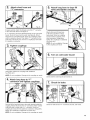
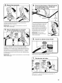
CONNECT INLET HOSES
For non-steam models, skip to "Connect Vent."
The dryer must be connected to the cold water faucet using
the new inlet hoses. Do not use old hoses.
1, Turn cold water off, remove and
replace rubber washer
®
®
®
Turn cold water faucet off and remove washer inlet hose.
Check and see if rubber washer is in the "Y" connector.
Remove old rubber washer from inlet hose and replace with
new rubber washer provided.
1®TEFLON is a registered trademark of E.L Dupont De Nemours and Company.
12

:2, Attach short hose and
"Y" connector
If space permits, attach the female end of the "Y" connector
to the cold water faucet. See figure A.
If "Y" connector cannot be attached directly to the cold water
faucet, the short hose must be used. See figure B. Attach
short hose to cold water faucet. Screw on coupling by hand
until it is seated on faucet. Then attach "Y" connector to the
male end of the short hose. Screw on coupling by hand until
it is seated on connector.
Using pliers, tighten the couplings with additional
two-thirds turn.
NOTE: Do not overtighten. Damage to the coupling can result.
valve and tighten coupling
Attach other end of long hose
to fill valve at bottom of dryer
back panel. Screw on coupling
by hand until it is seated on fill
valve connector. Using pliers,
tighten the couplings an additional
two-thirds turn.
NOTE: Do not overtighten. Damage
to the coupling can result.
Turn on cold water faucet
Check that the water faucets are turned on.
connector and tighten couplings
Check for leaks
One end of the long hose has a wire mesh strainer inside the
coupling. Attach this end to the "Y" connector. Attach washer
cold inlet hose to other side of "Y" connector. Screw on
coupling by hand until it is seated on connector. Using pliers,
tighten the couplings an additional two-thirds turn.
NOTE: Do not overtighten. Damage to the coupling can result.
Check for leaks around "Y" connector, faucets, and hoses.
13

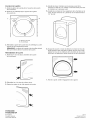
CONNECT VENT
, Connect vent to exhaust outlet
Using a 4" (102 mm) clamp, connect vent to exhaust outlet
in dryer. If connecting to existing vent, make sure vent is
clean. Dryer vent must fit over dryer exhaust outlet and inside
exhaust hood. Check that vent is secured to exhaust hood
with a 4" (102 mm) clamp.
2, Move dryer to final location
Move dryer to final location. Avoid crushing or kinking vent.
After dryer is in place, remove cardboard from under dryer.
LEVEL DRYER
1, Level Dryer
Place
level here
\
Place
level here
J
Check levelness of dryer from side to side. Repeat from
front to back.
NOTE: The dryer must be level for the moisture sensing
system to operate correctly.
Not Level LEVEL
2. Adjust leveling legs
Not Level
14
If dryer is not level, prop up using a wood block, use wrench
to adjust legs by backing out the foot as needed, then checking
again for levelness. Once legs are level, make sure all four legs
are snug against the floor.

COMPLETE INSTALLATION
CHECKLIST
[_ Check that all parts are now installed. If there is an extra
part, go back through steps to see what was skipped.
[_ Check that you have all of your tools.
[_ Dispose of/recycle all packaging materials.
[_ Be sure the water faucets are on.
[_ Check for leaks around "Y" connector, faucets, and hoses.
[_ Check dryer's final location. Be sure vent is not crushed
or kinked.
[_ Check that dryer is level. See "Level Dryer."
[_ Remove film on console and any tape remaining on dryer.
[_ Wipe dryer drum interior thoroughly with a damp cloth to
remove any dust.
[_ Read "Dryer Use" in your "Use and Care Guide."
[_ If you live in a hard water area, use of a water softener is
recommended to control the buildup of scale through the
water system in the dryer. Over time, the buildup of lime
scale may clog different parts of the water system, which will
reduce product performance. Excessive scale buildup may
lead to the need for certain part replacement or repair.
Electric Models:
[_ Pluginto a grounded outlet.
Gas Models:
[_ Check that gas supply is on.
[_ Check for leaks.
All Models:
[_ Select aTimed Dry heated cycle, and start dryer. Do not
select Air Only Temperature setting.
If dryer will not start, check the following:
• Controls are set in a running or "On" position.
Start button has been pushed firmly.
Dryer is plugged into an outlet and/or electrical supply is
connected.
Household fuse is intact and tight, or circuit breaker has
not tripped.
Dryer door is closed.
This dryer automatically runs an installation diagnostic routine
at the start of its first cycle.
NOTE: You may notice an odor when dryer is first heated. This
odor is common when heating element is first used. The odor will
go away.
REVERSE DOOR SWING
You can change your door swing from a right-side opening
to a left-side opening, if desired.
1. Place a towel or soft cloth on top of dryer or work space
to avoid damaging the surface.
Remove the door assembly
1. Open the dryer door.
2. Remove the bottom screw (B) from each of the two hinges
that attach dryer door to front panel of dryer.
3. Loosen the top screw (A)from each of the two hinges
in Step 2.
A
B
.A
B
4. Remove the dryer door and the hinges by lifting upward
on the door. Lay the door on a flat, covered surface, with
the inside of the door facing up. Remove remaining two
loose screws from dryer front panel.
5. Remove the 4 plastic plugs (A) located outside the dryer
door opening.
6. Install 4 plastic plugs (A) into screw holes in the dryer left
where the hinges were removed in Step 4.
15

Reverse the strike
1. Remove the door strike (A) from the dryer door opening.
2. Remove the cosmetic screw (B) opposite the door strike (A).
A
A. Door strike
B. Cosmetic screw
3. Reinstall the door strike and cosmetic screw on the opposite
side of dryer door opening from where they were removed.
NOTE: Door strike and plugs must be on the same side
of the dryer door opening.
Reinstall the door
1. Removethe 4 screws and two hinges from the dryer door.
2. Replace the 4 screws in the same holes
3. Remove the 4 screws from the opposite side of the door.
4. Install the two hinges to the front panel of the dryer using
4 screws. Use the non-slotted side to attach the hinge
to the front panel.
5. Install screws in top hinge holes in the door. Do not tighten
screws. Leave approximately 1/4" (5 mm) of screw exposed.
6. Hang door by placing screw heads into top slotted holes of
hinges and slide door down. Align bottom screw holes in hinge
and door. Install two bottom screws. Tighten all hinge screws.
7. Close door to engage door strike.
16

S]_CURIT]_ DE LA S]_CHEUSE
Votre s_curit_ et celle des autres est tr_s irnportante.
Nous donnons de nombreux messages de securit6 importants dans ce manuel et sur votre appareil m6nager. Assurez-vous de
toujours lire tousles messages de s6curit6 et de vous y conformer.
Voici le symbole d'alerte de s_curit&
Ce symbole d'alerte de s6curit_ vous signale les dangers potentiels de d6c_s et de blessures graves &vous
et &d'autres.
Tousles messages de securit6 suivront le symbole d'alerte de s6curit6 et le mot "DANGER" ou
"AVERTISSEMENT". Ces mots signifient :
Risque possible de d_c_s ou de blessure grave si vous ne
suivez pas imm_diaternent les instructions.
Risque possible de d_c_s ou de blessure grave si vous
ne suivez pas les instructions.
Tousles messages de s6curit_ vous diront quel est le danger potentiel et vous disent comment r6duire le risque de blessure et
ce qui peut se produire en cas de non-respect des instructions.
AVERT|SSEMENT -,,.i..oo d,i.o °dio,,
m
m
m
L'installation de la s_cheuse & linge dolt 6tre effectu_e par un installateur qualifi_.
Installer la s_cheuse conforrn_rnent aux instructions du fabricant et aux codes Iocaux.
Ne pas installer de s6cheuse & linge avec des mat6riaux d'6vacuation en plastique
souple ou un conduit rn6tallique souple (de type papier d'aluminium). Si un conduit
m6tallique souple est install6, celui-ci doit _tre d'un type sp6cifique identifi6 par le
fabricant de I'appareil et convenir a une utilisation avec les s6cheuses _ linge. Les
mat6riaux d'6vacuation souples sont connus pour s'affaisser, _tre facilement _cras6s
et bloquer la charpie. Ces situations obstrueront le d6bit d'air de la s6cheuse _ linge et
augmenteront le risque d'incendie.
Pour r6duire le risque de blessure grave ou de d_c_s, suivre routes
les instructions d'installation.
Conserver ces instructions.
iMPORTANT : Pour mettre I'ancienne s6cheuse au rebut ou pour la remiser, enlever la porte, i
17

AVERTISSEMENT : Pour votre s6curit6, les renseignements darts ce manuel doivent
_tre observes pour r6duire au minimum les risques d'incendie ou d'e×plosion ou pour
_viter des dommages au produit, des blessures ou un d6c_s.
- Ne pas entreposer ou utiliser de I'essence ou d'autres vapeurs ou liquides
inflammables _ proximit_ de cet appareil ou de tout autre appareil _lectrom_nager.
- QUE FAIRE DANS LE CAS D'UNE ODEUR DE GAZ :
• Ne pas tenter d'allumer un appareil.
= Ne pas toucher a un commutateur _lectrique; ne pas utiliser le t616phone se trouvant
sur les lieu×.
® l_vacuer tous les gens de la piece, de 1'6difice ou du quarrier.
®Appeler imm6diatement le foumisseur de gaz d'un t_16phone voisin. Suivre ses
instructions.
= A d6faut de joindre votre fournisseur de gaz, appeler les pompiers.
- L'installation et I'entretien doivent _tre effectu_s par un installateur qualifi6, une
agence de service ou le fournisseur de gaz.
AVERTISSEMENT : L'odorat ne permet pas toujours la detection d'une fuite de gaz.
Les distributeurs de gaz recommandent I'emploi d'un detecteur de gaz (homologation UL ou CSA).
Pour d'autre information, contacter le fournisseur de gaz local.
En cas de d6tection d'une fuite de gaz, ex6cuter les instructions "Que faire dans le cas d'une odeur de gaz".
IMPORTANT : L'installation du gaz dolt se conformer aux codes Iocaux, ou en I'absence de codes Iocaux, au code canadien
d'installation B149.1 du gaz naturel ou du propane.
La secheuse dolt _tre 61ectriquement reli6e & la terre conform6ment aux codes Iocaux, ou en I'absence de codes Iocaux, au Code
canadien de I'electricit6, CSA C22.1.
Dans I'Etat du Massachusetts, les instructions d'installation suivantes sont applicables :
[] Les travaux d'installation et r6paration doivent 6tre ex6cut6s par un plombier ou tuyauteur qualifi6 ou licenci6, ou par le
personnel qualifi6 d'une entreprise licenci6e par I'Etat du Massachusetts.
[] Si une vanne & boisseau sph6rique est utilis6e, elle dolt comporter une manette "T".
[] Si un conduit de raccordement flexible est utilis6, sa Iongueur ne doit pas d6passer 3 pi.
Avertissements de la proposition 65 de I'E_tatde Californie :
AVERTISSEMENT : Ce produit contient au moins un produit chimique connu par H_tat de Californie pour 6tre & I'origine de
cancers.
AVERTISSEMENT : Ce produit contient au moins un produit chimique connu par I'€:tat de Californie pour 6tre & rorigine de
malformations et autres deficiences de naissance.
18

EXIGENCES D'INSTALLATION
OUTILLAGE ET Pll_CES
Rassembler les outils et pieces n6cessaires avant d'entreprendre
I'installation. Lire et observer les instructions foumies avec
chacun des outils de la liste ci-dessous.
Outils n6cessaires _ toutes les installations :
Tournevis & lame plate
CI6 9,molette avec ouverture
jusqu'& 1" (25 mm) ou cl6 &
douille hexagonale
Niveau Brides de conduit
Compos6 d'6tanch6it6 des
raccords filet6s - r6sistant
au gaz propane
Pi_ces fournies (tous les modules) :
Pieds de nivellement (4)
pour modeles avec talon
Pieds de nivellement (4)
pour modeles sans talon
Pi_ces fournies (modUles _ vapeur) :
Couteau utilitaire
Pistolet & calfeutrage et
compos6 de calfeutrage
(pour I'installation d'un
nouveau conduit
d'6vacuation)
Raccord en "Y"
Tuyau d'alimentation
de 2' (0,6 m)
Cisaille de ferblantier
(pour I'installation d'un
nouveau conduit)
Tourne-6crou de 1/4"
(6 mm) (recommand6)
Metre-ruban Pince
Outils n6cessaires pour les installations _ gaz :
Tuyau d'alimentation
de 5' (1,52 m)
Rondelle en caoutchouc
Retirer lesachet de pieces du tambour de la s6cheuse. V6rifier
que toutes les pieces sont pr6sentes.
Pi_ces n6cessaires : (Non fourni avec la secheuse)
Consulter les codes Iocaux. V6rifier I'alimentation 61ectrique et le
circuit d'6vacuation existants. Voir "installations 61ectriques" et
"Exigences concernant 1'6vacuation" avant d'acheter les pieces.
Les installations pour maison mobile n6cessitent un systeme
d'6vacuation en m6tal disponible chez le marchand chez qui
vous avez achet6 votre s6cheuse. Pour plus d'informations, voir
la section "Assistance ou service" dans le "Guide d'utilisation et
d'entretien".
Mat6riel facultatif : (Non fourni avec la secheuse)
Consulter le "Guide d'utilisation et d'entretien" pour plus
d'informations sur les accessoires disponibles qui conviennent
& votre s6cheuse.
CI6 & tuyau de 8" (203 mm)
ou 10" (254 mm)
CI6 _,mollette de 8" (203 mm)
ou 10" (254 mm)
(pour le raccordement au gaz)
19

EXIGENCES D'EMPLACEMENT
Risque d'e×plosion
Garder les mati_res et les vapeurs inflammables, telle
que I'essence, loin de la s_cheuse.
Placer la s_cheuse au moins 460 mrn (18 po) au-dessus
du plancher pour une installation dans un garage.
Le non-respect de ces instructions peut causer
un d_c_s, une explosion ou un incendie.
II vous faudra :
[] Un emplacement permettant une 6vacuation appropri6e.
Voir "Exigences concernant 1'6vacuation".
[] Un circuit distinct de 15 ou 20 A est requis pour les
s6cheuses a gaz et un circuit distinct de 30 A est requis
pour les s6cheuses 61ectriques.
[] Si on utilise un cordon d'alimentation, une prise 61ectrique
reli6e a la terre situ6e a 2 pi (610 mm) maximum d'un des
c6t6s de la s6cheuse. Voir "Sp6cifications 61ectriques".
[] Le plancher dolt pouvoir soutenir le poids de la s6cheuse
de 200 Ib (90,7 kg). Tenir 6galement compte du poids des
appareils voisins.
[] Un plancher de niveau avec une pente maximale de
1" (25 mm) sous I'ensemble de la s6cheuse. Si I'inclinaison
est sup6rieure a 1" (25 mm), les v6tements peuvent ne pas
culbuter convenablement et les programmes de d6tection
automatiques peuvent ne pas fonctionner correctement.
[] Pour une installation dans un garage, placer la s6cheuse
au moins 18" (460 mm) au-dessus du plancher.
[] Modeles vapeur uniquement : Des robinets d'eau froide
situ6s a 4 pi (1,2 m) maximum des valves de remplissage,
et une pression d'eau de 20 a 100 Ib/po 2(137,9 a 689,6 kPa).
On peut utiliser I'alimentation en eau de la laveuse a I'aide
du raccord en "Y" fourni.
Ne pas faire fonctionner la s6cheuse a des temp6ratures
inf6rieures a 45°F (7°C). A des temp6ratures inf6rieures,
la s6cheuse risque de ne pas s'arr6ter a la fin d'un programme de
d6tection automatique. Ceci risque de prolonger les dur6es
de s6chage.
La s6cheuse ne dolt pas 6tre install6e ou remis6e dans un endroit
oQ elle sera expos6e a I'eau et/ou aux intemp6ries.
V6rifier les sp6cifications des codes. Certains codes limitent
ou interdisent I'installation des secheuses dans un garage,
un placard, une maison mobile ou une chambre a coucher.
Communiquer avec I'inspecteur en b&timents local.
REMARQUE : Aucun autre appareil consommant un combustible
ne dolt 6tre install6 dans le m6me placard.
DISTANCES DE Df=GAGEMENT A RESPECTER POUR
L'INSTALLATION
L'emplacement dolt 6tre assezgrand pour permettre d'ouvrir
completement la porte de las6cheuse.
DiMENSiONS DE LA S¢:CHEUSE
Mod_les avec talon
221/4"_ _ 30"---="
(565 turn) _
Vue lat_rale
441/2"
(1130 ram)
t
1/2"
(13 mrnl
63/4 I_
(171 ram)
f
f
:.1
(368mra)___l 11"
4"
(102 ram)
53/8" I
(137_mra) 1
(25 ram)
(279 ram)
Vue artiste
Mod_les sans talon
221/4"_
(565 rnm) (70a.,ra)F
Vue lat_rale
42V2"
(1080 ram)
13/_,,
(35 rnm)
43/4"
(121 ram)
f" "m
2"
(51 ram)
33/8" I
O_ ._
(368 ram) --_1 11
(25 ram}
(279 mra}
Vue arri_re
Vue de dGSSOUS:
/ x
]
_-14V="-_-"_-14V_"-_-
(368 ram) (368 ram)
REMARQUE : La plupart des installations requierent
un espace minimum de 5" (127 mm) derriere la s_cheuse pour
le conduit d'_vacuation avec coude. Voir "Exigences concernant
I'_vacuation".
2O
La page charge ...
La page charge ...
La page charge ...
La page charge ...
La page charge ...
La page charge ...
La page charge ...
La page charge ...
La page charge ...
La page charge ...
La page charge ...
La page charge ...
-
 1
1
-
 2
2
-
 3
3
-
 4
4
-
 5
5
-
 6
6
-
 7
7
-
 8
8
-
 9
9
-
 10
10
-
 11
11
-
 12
12
-
 13
13
-
 14
14
-
 15
15
-
 16
16
-
 17
17
-
 18
18
-
 19
19
-
 20
20
-
 21
21
-
 22
22
-
 23
23
-
 24
24
-
 25
25
-
 26
26
-
 27
27
-
 28
28
-
 29
29
-
 30
30
-
 31
31
-
 32
32


Maytag YMEDB725BW0 Guide d'installation
- Taper
- Guide d'installation
- Ce manuel convient également à
dans d''autres langues
Documents connexes
-
Whirlpool YWED95HEDW0 Guide d'installation
-
Maytag MGDE201YW2 Guide d'installation
-
Maytag MGD7000XW2 Guide d'installation
-
Whirlpool MGDX600XL0 Guide d'installation
-
Whirlpool MGDE500VF1 Guide d'installation
-
Roper NGD5100TQ1 Guide d'installation
-
Whirlpool 3DWGD4815FW0 Guide d'installation
-
-
Whirlpool MGD3000BW1 Guide d'installation