KitchenAid KSSS42QTB04 Guide d'installation
- Taper
- Guide d'installation

Kitchen_kid _
SIDE BY SIDE BUILT-IN REFRIGERATOR
IMPORTANT: READ AND SAVE THESE INSTRUCTIONS. INSTALLATION REQUIRES 2 OR MORE PEOPLE.
REFRIGERADOR EMPOTRADO
DE DOS PUERTAS
/_,, _......
IMPORTANTE: LEA Y GUARDE ESTAS INSTRUCCIONES. LA INSTALACION REQUIERE DE 20 MAS PERSONAS.
REFRIGERATEUR ENCASTRE COTE A COTE
IMPORTANT : LIREETCONSERVERCES INSTRUCTIONS.L'INSTALLATIONNC:CESSITEL'INTERVENTIONDE 2 PERSONNESOU PLUS.
Table of Contents/indice/Table des matieres .................................................................. 2
W10291426A

TABLE OF CONTENTS
REFRIGERATOR SAFETY ........................................................................... 3
MODELS ....................................................................................................... 4
INSTALLATION REQUIREMENTS ............................................................. 6
Tools and Parts ......................................................................................... 6
Location Requirements ............................................................................. 6
Electrical Requirements ............................................................................ 7
Water Supply Requirements ..................................................................... 8
Tipping Radius .......................................................................................... 8
Product Dimensions ................................................................................. 9
Door Swing Dimensions ......................................................................... 10
Overlay Series Door Panel and Cabinetry Clearance ............................ 11
Overlay Series Custom Panels and Handle Kits .................................... 13
Classic Series Factory Panels and Kits .................................................. 15
Classic Series Custom Panels ................................................................ 16
Classic, Architect ®and Complete Series Custom Side Panels ............. 17
Overlay Series Custom Side Panels ....................................................... 18
INSTALLATION INSTRUCTIONS ............................................................. 19
Unpack the Refrigerator ......................................................................... 19
Reduce Tipping Radius .......................................................................... 19
Move the Refrigerator into House .......................................................... 19
Install Anti-Tip Boards ............................................................................ 20
Connect the Water Supply ..................................................................... 20
Plug in Refrigerator ................................................................................. 21
Move Refrigerator to Final Location ....................................................... 22
Level and Align Refrigerator ................................................................... 22
Install Classic Series Custom Panels ..................................................... 23
Install Overlay Series Custom Panels .................................................... 23
Adjust Doors ........................................................................................... 24
Install Side Panel .................................................................................... 25
Install Base Grille .................................................................................... 25
Complete Installation .............................................................................. 26
Water System Preparation ..................................................................... 26
p
INDICE
SEGURIDAD DEL REFRIGERADOR ........................................................ 27
MODELOS .................................................................................................. 28
REQUlSlTOS DE INSTALAClON .............................................................. 30
Piezas y herramientas ............................................................................. 30
Requisitos de ubicaci6n ......................................................................... 30
Requisitos electricos ............................................................................... 31
Requisitos del suministro de agua ......................................................... 32
Arco de vuelco ........................................................................................ 32
Medidas del producto ............................................................................. 33
Medidas de oscilaci6n de las puertas .................................................... 34
Espacio para el panel de la puerta y
para los armarios de la serie Overlay ..................................................... 35
Paneles a la medida y juegos de agarraderas de la serie Overlay ........ 37
Paneles y juegos de f&brica de la serie Classic ..................................... 39
Paneles a la medida para la serie Classic .............................................. 40
Paneles laterales a la medida para las
series Classic, Architect ®y Complete .................................................... 41
Paneles laterales a la medida para la serie Overlay ............................... 42
INSTRUCCIONES DE INSTALACION ...................................................... 43
Desempaque el refrigerador ................................................................... 43
C6mo reducir el arco de vuelco ............................................................. 43
C6mo hacer entrar el refrigerador en lacasa ........................................ 44
C6mo instalar los tableros antivuelco .................................................... 44
Conexi6n del suministro de agua ........................................................... 45
C6mo enchufar el refrigerador ............................................................... 46
C6mo mover el refrigerador a su ubicaci6n final ................................... 47
Nivelaci6n y alineamiento del refrigerador ............................................. 47
C6mo instalar los paneles a la medida para la serie Classic ................. 48
C6mo instalar los paneles a la medida para la serie Overlay ................ 48
Ajuste las puertas ................................................................................... 49
C6mo instalar el panel lateral ................................................................. 50
C6mo instalar la rejilla de la base ........................................................... 50
C6mo terminar la instalaci6n .................................................................. 51
Preparaci6n del sistema de agua ........................................................... 51
TABLE DES MATIERES
SI_CURITI_ DU RI_FRIGI_RATEUR ........................................................... 52
MOD#LES .................................................................................................. 53
EXIGENCES D'INSTALLATION ................................................................ 55
Outillage et pieces .................................................................................. 55
Exigences d'emplacement ..................................................................... 55
Specifications _lectriques ...................................................................... 56
Specifications de I'alimentation en eau.................................................. 57
Rayon de basculement ........................................................................... 57
Dimensions du produit ............................................................................ 58
Dimensions pour I'ouverture des portes ................................................ 59
S_rie Overlay - Panneau de porte et placard - espace libre .................. 60
Panneaux personnalis6s et poignees de la serie Overlay ...................... 62
Ensembles de panneaux d'origine de la serie Classic ........................... 64
Panneaux personnalis6s de la S6rie Classic .......................................... 65
Panneaux lat6raux personnalises des
S_ries Classic, Architect ®et Complete ................................................... 66
Panneaux lat6raux personnalises de la S6rie Overlay ........................... 67
INSTRUCTIONS D'INSTALLATION ......................................................... 68
Deballage du refrigerateur ...................................................................... 68
Reduction du rayon de basculement ..................................................... 68
Faire entrer le refrigerateur dans le domicile .......................................... 69
Installation de planches antibasculement .............................................. 69
Raccordement a I'alimentation en eau................................................... 70
Brancher le r6frig6rateur ......................................................................... 71
Deplacement du r6frig_rateur a I'emplacement final ............................. 72
R_glage de I'aplomb et alignement du r6frig6rateur .............................. 72
Installation des panneaux personnalises de la S_rie Classic ................ 73
Installation des panneaux personnalises de la S6rie Overlay ................ 73
Ajustement des portes ............................................................................ 74
Installation du panneau lat6ral ................................................................ 75
Installation de la grille de la base ........................................................... 75
Achever I'installation ............................................................................... 76
Preparation du syst_me d'eau ............................................................... 76
2

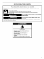
REFRIGERATOR SAFETY
Your safety and the safety of others are very important.
We have provided many important safety messages in this manual and on your appliance. Always read and obey all safety
messages.
This is the safety alert symbol.
This symbol alerts you to potential hazards that can kill or hurt you and others.
All safety messages will follow the safety alert symbol and either the word "DANGER" or "WARNING."
These words mean:
You can be killed or seriously injured if you don't immediately
follow instructions.
You can be killed or seriously injured if you don't follow
instructions.
All safety messages will tell you what the potential hazard is, tell you how to reduce the chance of injury, and tell you what can
happen if the instructions are not followed.
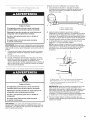
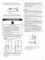
Tip Over Hazard
Refrigerator is top heavy and tips easily when not
completely installed.
Keep doors taped closed until refrigerator is
completely installed.
Use two or more people to move and install
refrigerator.
Failure to do so can result in death or serious injury.

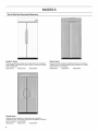
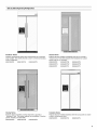
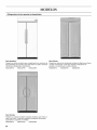
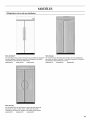
MODELS
Side by Side Non-Dispensing Refrigerators
Architect _ Series
Features wraparound styling that complements the contoured
door handles. This series provides a warm commercial-looking
built-in refrigerator.
KSSC36FTS KSSC42FTS KSSC48FTS
Classic Series
Features factory-installed, traditional style trim to provide a
"framed" look. This series requires the installation of custom
panels that are not included.
KSSS36FTX KSSS42FTX KSSS48FTX
Overlay Series
Features factory-installed, overlay style trim to provide a
"frameless" look. This series requires the installation of custom
panels, handles, and standoffs.
KSSO36FTX KSSO42FTX KSSO48FTX

Side by Side Dispensing Refrigerators
Architect _ Series
Features wraparound styling that complements the contoured
door handles. This series provides a warm commercial-looking
built-in refrigerator.
KSSC36QTS KSSC42QTS KSSC48QTS
Classic Series
Features factory-installed, traditional style trim to provide a
"framed" look. This series requires the installation of custom
panels that are not included.
KSSS36QTB KSSS42QTB KSSS48QTB
KSSS36QTW KSSS42QTW KSSS48QTW
KSSS36QTX KSSS42QTX KSSS48QTX
i i i i iii ii i I iiii_ i i
iii_ _ i ii_
ii_il i
i_ iii _ii
ii
ii ii
Overlay Series
Features factory-installed, overlay style trim to provide a
"frameless" look. This series requires the installation of custom
panels, handles, and standoffs.
KSSO36QTB KSSO42QTB KSSO48QTB
Complete Series
Features factory-installed stainless steel trim and panels to create
a sleek, contemporary look.
KSSP36QTS KSSP42QTS KSSP48QTS

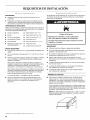
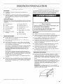
INSTALLATION REQUIREMENTS
IMPORTAN1"."
• Installer: Leave Installation Instructions with the homeowner.
• Homeowner: Keep Installation Instructions for future
reference. Save these Installation Instructions for the local
electrical inspector's use.
TOOLS NEEDED:
Gather the required tools and parts before starting installation.
Read and follow the instructions provided with any tools listed
here.
• Cordless drill
• Drill bits
• Two adjustable
wrenches
• Phillips screwdriver
• Small level
• Appliance dolly
• Torx®tT27 screwdriver
• 1V32"nut driver
• 3/8"and 1/2"open-end wrenches
• 8/32" Allen wrench
• 1/4"and _e" socket drivers
• Tape measure
• Utility knife
PARTS NEEDED:
• Six #8 x 3" (7.6 cm) wood screws (longer screws may be needed)
• One or two 2" x 4" x 32" (5 cm x l0 cm x 81 cm)woodboard(s)
• Order factory panels, make custom panels or consult a
qualified cabinetmaker or carpenter to make the panels.
Classic Series: Order factory panels, make custom panels, or
consult a qualified cabinetmaker or carpenter to make the
panels. See "Classic Series Custom Panels" for more
information.
Overlay Series: Make custom panels, or consult a qualified
cabinetmaker or carpenter to make the panels. See "Overlay
Series Custom Panels and Handle Kits" for more information.
Architect ®and Complete Series are shipped complete.
If you are connecting the water line directly to copper tubing
and not to a shutoff valve, you need a ferrule, a union, and a
1/4"(6.35 mm) compression fitting.
The refrigerator can be recessed in an opening between cabinets
or installed at the end of a cabinet run using a side panel to
enclose the refrigerator.
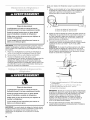
Explosion Hazard
Keep flammable materials and vapors, such as
gasoline, away from refrigerator.
Failure to do so can result in death, explosion, or fire.
IMPORTANT:
• Observe all governing codes and ordinances.
• It is recommended that you do not install the refrigerator near
an oven, radiator, or other heat source.
• Do not install in a location where the temperature will fall
below 55°F (13°C).
• Floor must support the refrigerator weight, more than 600 Ibs
(272 kg), door panels and contents of the refrigerator.
• Ceiling height must allow for side tipping radius. See "Tipping
Radius."
• Location should permit door to open fully. See "Door Swing
Dimensions."
• Location must permit top grille removal. See "Opening
Dimensions."
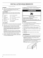
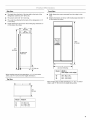
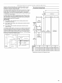
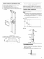
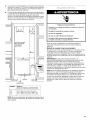
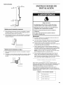
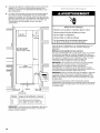
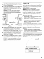
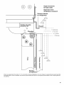
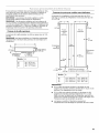
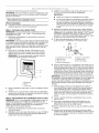
Opening Dimensions
To avoid tipping during use, the solid soffit must be within 1"
(2.5 cm) maximum above the refrigerator. If the solid soffit is
higher than 1" (2.5 cm) or one is not available, then the
refrigerator must be braced.
If the anti-tip boards are needed, they must be attached to the
rear wall studs 80" to 90" (203 cm to 229 cm) above the floor.
See "Install Anti-Tip Boards" for more information.
NOTE: A clearance of 1/2"(1.3 cm) must be maintained above
the top grille in order for the top grille to be removed.
I"®TORX is a registered trademark of Textron Innovations Inc.
6

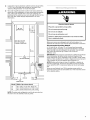
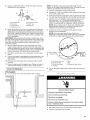
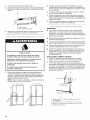
A grounded 3 prong electrical outlet should be placed within
4" (10.2 cm) of the right side cabinets or end panel. See
"Electrical Requirements" for more information.
The water shutoff should be located in the base cabinet on
either side of the refrigerator or some other easily accessible
area. If the water shutoff valve is not in the cabinets, the
plumbing for the water line can come through the floor or the
back wall. See "Water Supply Requirements" for more
information.
0
Model Width A (as shown above)
36 351/2"(90.2 cm) to 353/4'' (90.8 cm)
42 41 W' (105.4 cm) to 413/4"(106.1 cm)
48 471/2"(120.7 cm) to 473/4'' (121.3 cm)
NOTE: Flooring under refrigerator must be at same level as
the room. Face of cabinetry must be plumb.
Electrical Shock Hazard
Plug into a grounded 3 prong outlet.
Do not remove ground prong.
Do not use an adapter.
Do not use an extension cord.
Failure to follow these instructions can result in death,
fire, or electrical shock.
Before you move your refrigerator into its final location, it is
important to make sure you have the proper electrical connection.
Recommended Grounding Method
A 115 Volt, 60 Hz., AC only, 15- or 20-amp fused, grounded
electrical supply is required. It is recommended that a separate
circuit serving only your refrigerator be provided. Use an outlet
that cannot be turned off by a switch. Do not use an
extension cord.
IMPORTANT: If this product is connected to a GFCI (Ground Fault
Circuit Interrupter) protected outlet, nuisance tripping of the
power supply may occur, resulting in loss of cooling. Food quality
and flavor may be affected. If nuisance tripping has occurred, and
if the condition of the food appears poor, dispose of it.
NOTE: Before performing any type of installation, cleaning, or
removing a light bulb, remove the top grille and turn the master
power switch to OFF or disconnect power at the circuit breaker
box.
When you are finished, turn ON the master power switch or
reconnect power at the circuit breaker box. Then reset the control
to the desired setting.

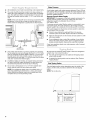
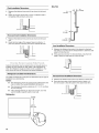
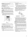
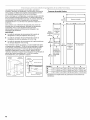
Allinstallationsmustmeetlocalplumbingcoderequirements.
Thewatershutoffshouldbelocatedinthebasecabineton
eithersideoftherefrigeratororsomeothereasilyaccessible
area.Theright-handsideisrecommended.Theaccesshole
throughthecabinetmustbewithinW' (12.7 mm) of the rear
wall.
NOTE: If the water shutoff valve is in the back wall behind the
refrigerator, it must be at an angle so that the tube is not
kinked when the refrigerator is pushed into its final location.
6"
(15.2 cm)
24 u
(60.96 cm) min.
If the water shutoff valve is not in the cabinets, the plumbing
for the water line can come through the floor. A V2"(12.7 mm)
hole for plumbing should be drilled at least 6" (15.2 cm) from
the right or left hand side cabinet or panel. On the floor, the
hole should be no more than 1" (2.54 cm) away from the back
wall. See "Connect the Water Supply."
If additional tubing is needed, use copper tubing and check
for leaks. Install the copper tubing only in areas where the
household temperatures will remain above freezing.
Do not use a piercing-type or 3Ae"(4.76 mm) saddle valve
which reduces water flow and clogs more easily.
NOTE: Your refrigerator dealer has a kit available with a V4"
(6.35 mm) saddle-type shutoff valve, a union, and copper
tubing. Before purchasing, make sure a saddle-type valve
complies with your local plumbing codes.
Water Pressure
A cold water supply with water pressure between 30 and 120 psi
(207 and 827 kPa) is required to operate the water dispenser and
ice maker. If you have questions about your water pressure, call a
licensed, qualified plumber.
Reverse Osmosis Water Supply
IMPORTANT: The pressure of the water supply coming out of a
reverse osmosis system going to the water inlet valve of the
refrigerator needs to be between 30 and 120 psi
(207 and 827 kPa).
If a reverse osmosis water filtration system is connected to your
cold water supply, the water pressure to the reverse osmosis
system needs to be a minimum of 40 to 60 psi (276 to 414 kPa).
If the water pressure to the reverse osmosis system is less than
40 to 60 psi (276 to 414 kPa):
• Check to see whether the sediment filter in the reverse
osmosis system is blocked. Replace the filter if necessary.
• Allow the storage tank on the reverse osmosis system to refill
after heavy usage.
• If your refrigerator has a water filter cartridge, it may further
reduce the water pressure when used in conjunction with a
reverse osmosis system. Remove the water filter cartridge.
If you have questions about your water pressure, call a licensed,
qualified plumber.
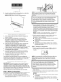
Be sure there is adequate ceiling height to stand the refrigerator
upright when it is moved into place.
• The dolly wheel height must be added to the tipping radius
when a dolly is used.
• If needed, the tipping radius can be reduced. See "Reduce
Tipping Radius."
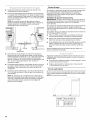
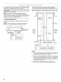
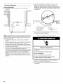
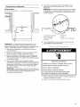
Side Tipping Radius
The side tipping radius varies depending upon the width of the
model. Use the chart provided to determine the side tipping
radius.
NOTE: Tip on side only.
s II
/
/
/
/
/
/
/
/
/
i I
/
/
ii
I
I
I
t
f
ii ii
Model
36
42
48
Tipping Radius A
90W' (229.9 cm)
93" (236.2 cm)
96" (243.8 cm)
8

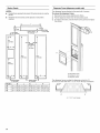
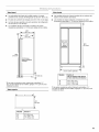
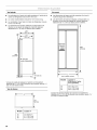
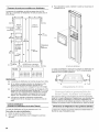
Side View
• The depth from the front of the top grille to the back of the
refrigerator cabinet is 253/8'' (64.5 cm).
• The power cord is 84" (213 cm) long.
• The water line attached to the back of the refrigerator is 5 ft
(1.5 m) long.
• Height dimensions are shown with leveling legs extended V8"
(3 mm) below the rollers.
"833/8"
(211.8 cm)
T =
____ 25%"
(64.5 cm)
231/2"
_"_(59.7 cm) _
84" (213.4 cm)
Power Cord
"31/2" (8.9 cm)
*When leveling legs are fully extended to 1V4"(3.2 cm) below
rollers, add 1V8"(2.9 cm) to the height dimensions.
Top View
A
Model Width A
36 35" (88.9 cm)
42 41" (104.1 cm)
48 47" (119.4 cm)
T
253/8''
(64.5 cm)
Front View
• Width dimensions were measured from trim edge to trim
edge.
• Height dimensions are shown with leveling legs extended V8"
(3 mm) below the rollers.
A
(see chart following)
v
*83%"
(211.8 cm)
Model Width A
(Trim edge to trim edge)
36 36%" (92.1 cm)
42 42V4" (107.3 cm)
48 48%" (122.6 cm)
*When leveling legs are fully extended to 1V4"(3.2 cm) below
rollers, add 1V8"(2.9 cm) to the height dimensions.

r_w "¸"_ _7"_ "_{ii?{meos:{o:os
_3
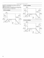
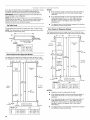
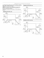
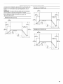
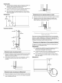
The location must permit both doors to open to a minimum of 90°.
Allow 4W' (11.4 cm) minimum space between the side of the
refrigerator and a corner wall.
NOTE: More clearance may be required if you are using overlay
panels, custom handles, or extended handles on a Classic model.
To adjust the door swing, see "Adjust Doors."
36" (91.4 cm) Models
107/8"
(27.6 cm)
.;c;
<---143/8 ".-> |
(36.5 cm) |
443/8,,
(112.7 cm)
42" (106.7 cm) Models
48" (121.9 cm) Models
143/8"
(36.5 cm)
99 m)
(1
(11 41"cm)l
(48.9 cm)
513/8"
(130.5 cm)
10

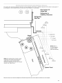
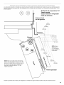
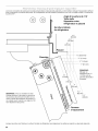
The custom door panels and adjacent cabinetry must be designed so that there is sufficient clearance for the doors to swing open. If
the refrigerator is to be installed close to the wall, see "Door Swing 90°,' on next page.
Door Swing 110 °
Actual Size
Refrigerator to
Cabinetry Clearance
Refrigerator
Side Trim
Hinge
®
NOTE: For Overlay Series models, rout the
hinge side of the custom door panels to a
radius that is equal to at least half the
thickness of the panel if a 130° door swing is
desired. See "Adjust Doors."
£
Panel
When the doors are closed the refrigerator will extend beyond the face of the adjacent cabinetry to some degree.
11

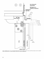
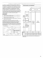
90 ° Door
Stop Position
O
Hinge
®
0
0
,i I
Door Swing 90 °
Actual Size
Refrigerator to
Cabinetry Clearance
Refrigerator
Side Trim
11
(2.5 cm)
3/4"
(1.9 cm)
1/ . i
/2 ,,
(1.3,cm)i
,, ,,
i i
i i
Cabin,'etr_/
---1 .... i----4
1/2"
(1.3cm)
3/4"
(1.9 cm) i
I 1"
(2.5cm)
0
<
i
i
1/4"(6.35 mm)
1/2"(1.3 cm)
3/4"(1.9 cm)
1" (2.5 cm)
11/4"
(3.2 cm)
11/2"
(3.8cm)
Spacer Panel
Allow a minimum of 41/2'' (11.4 cm) of space between the side of the refrigerator and a corner wall. More clearance may be needed if
thicker custom panels or custom handles are used. Do not overlook baseboards.
12

(_4_,_;_ __ __,_ P_Q:tc a_ },{a_d_ _6_
Custom overlay panels allow you to blend the exterior of your
refrigerator into the overall kitchen decor, and to use custom
handles for additional design flexibility.
The custom panels must have backer panels attached in order to
mount them to the refrigerator. It is most common to work with
three panels, as shown in the following graphic: a decorative
overlay panel, a %" (3.18 mm) spacer panel or spacer strips and a
V4" (6.35 mm) backer panel.
In some cases, your cabinet manufacturer may choose to work
with one panel routed for the different dimensions. Follow these
panel dimension and placement instructions to be sure that the
custom overlay panels will fit properly.
IMPO RTANT:
• The weight of the refrigerator door overlay panel cannot
exceed 50 Ibs (23 kg).
• The weight of the freezer door overlay panel cannot exceed
40 Ibs (18.1 kg).
• The weight of the top grille overlay panel cannot exceed
10 Ibs (4.5 kg).
To minimize panel weight, you may use 2" (5.08 cm) spacer strips
around the perimeter in place of full-sheet solid spacer panels.
The spacer strips must be set in at least 1" (2.54 cm) from the top,
bottom and sides edges of the backer panel. Ifyou use spacer
strips, it is also recommended that you use two 2" (5.08 cm) strips
horizontally centered for added support.
I
Spacer Panel I
Overlay
Panel
Spacer Panel
Overlay Panel
Backer Panel
,,
I_ 1" minimum
I (2.54 cm) f ......
Trim
I .....
_,_ Offset Dimension
I
5/8"to 3/4"
(15.88 to
19.05 ram)
Backer Panel
1/4"
%" (6.35 ram)
(3.18 ram)
Decorative Overlay Panel
Preferred
Radius
1/2,,
(1.27 em)
\
141/4"
(36.2 cm)
337/8 ''
(86.0em)
1
,_------- A ---------_
Freezer
Door Panel
(Dispenser)
-'_--10%"---_ _
(27.6 era) iI
Dispenser
cutout is
centered
left-to-right
Refrigerator
Door Panel
Model A B C
36 143/4'' (37.47 cm) 193/4'' (50.17 cm) 343/4'' (88.27 cm)
42 17V4" (43.82 cm) 23V4" (59.06 cm) 403/4'' (103.51 cm)
48 193/4'' (50.17 cm) 263/4'' (67.95 cm) 463/4'' (118.75 cm)
*Represents placement of dispenser frame.
13

Backer Panels
NOTES:
• Dashed lines represent placement of backer panels on overlay
panels.
• Illustration shows backer panels placed on decorative
overlays.
, !
(15.7 cm) e Offset
/_" Bottom Offset___ 1/2"(12.7 mm)
Top Offset 1/2" (1.27 cm)
-- 1%" (4.13 cm)
-i- ....
22"
(55.9 cm)
f
331/4''
(84.5 cm)
Model
36
42
48
t Bottom Offset
1/8" (3.2 ram)
D
141/4'' (36.20 cm)
163/4'' (42.55 cm)
191/4'' (48.90 cm)
I
I
I
I
Handle-
Side Offset
1/4"
(6.4 mm)
701/2"
(179.1 em)
701/2''
(179.1 cm)
<.-
Bottom Offset ___
1/8" (3.2 mm)
E F
191/4'' (48.90 cm) 333/4'' (85.73 cm)
223/4'' (57.79 cm) 393/4'' (100.97 cm)
261/4'' (66.68 cm) 453/4'' (116.21 cm)
Dispenser Frame (dispenser models only)
The dispenser frame attaches to the panel with 4 screws.
To remove the dispenser frame:
1. Remove the four screws attaching the frame.
2. Pull the dispenser frame from the decorative panel.
3. To replace the frame, hold the frame to the panel and replace
the screws.
/
A. Decorative panel
B. Refrigerator door
C. Dispenser frame
The dispenser frame overlaps the dispenser cutout by 5/le"
(0.78 cm) on each side and 1/2"(1.27 cm) on the top and bottom.
A
/
A
A. ½" (1.27 cm) Overlap
14

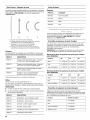
Overlay Series Door Handle Kits
The following handle styles are available. Contact your KitchenAid
dealer or KitchenAid Parts and Accessories at
1-800-442-9991. In Canada, call 1-800-807-6777.
Architect _ Series
Handles
PART NO. COLOR
4396103 Stainless Steel
8171760 Biscuit
4396105 White
4396106 Black
B C D
A. Architect _Series handle (4396103)
B. Flat end straight handle (4396776) with stainless
steel clamshell standoffs (4396775)
C. Round end arc handle (4396779) with bronze bullet
standoffs (4396778)
D. Round end semicircle (4396777) with stainless steel
cylinder standoffs (4396782)
Handles
These handles can be installed on side-by-side and bottom-
freezer refrigerators that require overlay panels.
PART NO. DESCRIPTION
4396776 Flat End Straight - 21" (53.3 cm) Length,
Satin Stainless Steel
4396781 Flat End Straight - 45" (114.3 cm) Length,
Satin Stainless Steel
4396777 Round End Semicircle,
Satin Stainless Steel*
4396779 Round End Arc,
Satin Stainless Steel*
*Availablefor non-dispensing models only.
Standoffs
The kit includes screws to support 3/4" applications.
Standoffs can be installed on side-by-side and bottom-freezer
refrigerators that require overlay panels.
NOTES:
• Two standoffs must be ordered for each handle.
• Handles and standoffs may be combined to meet your
individual decorating needs.
PART NO. DESCRIPTION
4396775 Clamshell, Satin Stainless Steel
4396780 Clamshell, Satin Bronze
4396774 Bullet, Satin Stainless Steel
4396778 Bullet, Satin Bronze
4396782 Cylinder, Satin Stainless Steel
4396773 Cylinder, Satin Bronze
All factory parts are available through your KitchenAid dealer or by
calling KitchenAid Parts and Accessories at 1-800-442-9991. In
Canada, call 1-800-807-6777.
Factory Door Panel Kits
Three kits containing colored acrylic or stainless steel door and
top grille panels are available. Follow the kit instructions for
installing the panels.
NOTE: Panel kits are not required for factory-installed stainless
steel panel models.
Door Panel Part Numbers for Non-dispenser Models
Color 36 42 48
White #2325136 #2325137 #2325138
Black #2325139 #2325140 #2325141
Stainless Steel #2325142 #2325143 #2325144
Door Panel Part Numbers for Dispenser Models
Color 36 42 48
White #2325127 #2325128 #2325129
Black #2325130 #2325131 #2325132
Stainless Steel #2325133 #2325134 #2325135
Extended Door Handle Kits
Use extended door handles when additional finger clearance is
needed between the door handles and custom panel. Follow the
kit instructions for installing the door handles.
Color Part Number
White #4387990
Black #8171418
Stainless Steel #4388062
Matte Aluminum #4387989
15

If you plan to install custom wood panels, you will need to create
the panels yourself or consult a qualified cabinetmaker or
carpenter. See dimension drawings for panel specifications.
IMPORTANT: Panels weighing more than recommended may
cause damage to your refrigerator.
NOTE: Dimensions shown have a (+)Vlo" (1.5 mm) tolerance.
Panels that are more than V4"(6.35 mm) thick must be routed. If
panels are less than V4"(6.35 mm) thick, install a filler panel
between the doors and decorative panels.
Top Grille Panel
The top grille panel should not weigh more than 10 Ibs (4.5 kg).
NOTE: The dashed lines in the illustration represent the location
and offsets of raised wood panel.
7" i
(17.78 cm) _ e Offsets
v. "I 7/16"(1.11 cm)
Top & Bottom Offsetsj
1/4"thick 11/16"(1.75 cm)
plywood
Model A
36 34V4" (87.0 cm)
42 40V4" (102.2 cm)
48 46V4" (117.5 cm)
Door Panels for Non-dispenser Models
The freezer panel should not weigh more than 40 Ibs (18.1 kg).
The refrigerator panel should not weigh more than 50 Ibs (23 kg).
_t_
7-
1,/2,,
(1.27 cm)
r ..... I
I
I
I
I
Freezer
Door
Non-Dispenser)
3,/_%,J
(8.3 cm) ,
I
I
I
I
t'
1/2,,
(1.27cm)
[.,_-- B ---------------_
Refrigerator
Door
Location and offsets
of raised wood panel
_t
7-
1/2,,
(1.27 cm)
7//16"
(1.1 cm)
W' thick
plywood
_t
7-
1/2,,
(1.27 cm)
Model A B
36 141/4"(36.2 cm) 191/4"(48.9 cm)
42 163/4'' (42.6 cm) 223/4"(57.8 cm)
48 19V4"(48.9 cm) 26V4" (66.7 cm)
NOTES:
• Ifthe standard handle is used, the handle side offset of
both panels should be 3V4" (8.25 cm) to all for finger
clearance.
If an extended handle is used, the handle side offset of
both panels should be 7/lo"(1.1 cm). Make sure the
refrigerator location allows the doors with extended
handles to open to 90 degrees. See "Door Swing
Dimensions."
The dashed lines in the illustration represent the location
and offsets of raised wood panel.
Door Panels for Dispenser Models
The freezer panel should not weigh more than 40 Ibs (18.1 kg).
The refrigerator panel should not weigh more than 50 Ibs (23 kg).
_t _-_ A-_
7-
1/2,,
(1.27 cm)
141/4"
(36.2 cm)
333/4"
(85.7 cm)
I-- ..... I
I
I
I
I
Freezer
Door
(Dispenser)
I
I
I
-----.
Dispenser
cutout is
centered
left-to-right
I
I
31/4'_m,4
(8.3 cm) ,
I
I
I
.... t
_--B_
r
Refrigerator
Door
I
i_-- 31/4"
, (8.3 cm)
1/2,,
(1.27 cm)
Model A B
36 141/4"(36.2 cm) 191/4"(48.9 cm)
42 163/4"(42.6 cm) 223/4"(57.8 cm)
48 19V4"(48.9 cm) 26V4" (66.7 cm)
±
7-
1/2,,
(1.27 cm)
7_6"
(1.1 cm)
........V4"thick
plywood
7-
Location andoffsets W'
of raisedwood panel (1.27cm)
NOTES:
• Dispenser cutout is centered left-to-right.
• Ifthe standard handle is used, the handle side offset of
both panels should be 3V4" (8.25 cm) to all for finger
clearance.
If an extended handle is used, the handle side offset of
both panels should be 7/lo"(1.1 cm). Make sure the
refrigerator location allows the doors with extended
handles to open to 90 degrees. See "Door Swing
Dimensions."
The dashed lines in the illustration represent the location
and offsets of raised wood panel.
16

Dispenser Frame (Classic series dispenser models)
The dispenser frame attaches to the panel with 4 screws.
To remove the dispenser frame:
1. Remove the four screws attaching the frame.
2. Pull the dispenser frame from the decorative panel.
3. To replace the frame, hold the frame to the panel and replace
the screws.
/
A.Dispenser frame
The dispenser frame overlaps the dispenser cutout by %e"
(0.78 cm) on each side and 1/2"(1.27 cm) on the top and bottom.
A. ½" (1.27 cm) Overlap
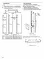
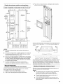
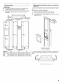
Custom side panels may be needed when not enough space is
available to have cabinets on both sides of the refrigerator or
when the refrigerator is placed at the end of a cabinet run. You
may choose an Inset, Flush, or Recessed Inset panel installation.
Refrigerator and Side Trim Dimensions
The width and height of a side panel are determined by the type of
installation you are planning.
NOTES:
• The dimensions shown are actual product dimensions and
may not reflect the needed panel installation dimensions.
• The side panel should be a minimum of 1/2"(1.27 cm) thick
to avoid warping.
• Ifthe opening depth is 25" (63.5 cm) or more, you may
want to install a support board on rear wall.
Refrigerator
241/8"
(61.3 cm)
2311A6,,
(60.3 cm)
231/2"
(59.7 cm)
Side Trim
(6.35 mm)
3/16"
(4.7 mm)
11_4"
(4.5 mm)
1%2" (10 mm)
(15.7 mm)
Inset Installation Dimensions
1. Measure the distance from point A (as shown) to the back
wall. Add 7/32"(5,6 mm) to this measurement to allow the side
panel to fit into the trim.
2. If the panel is more than 1/4"(6.35 mm) thick, route the front
edge to allow the side panel to fit into the trim.
17

Flush Installation Dimensions
1. Measure the distance from point A (as shown) to the back
wall.
2. Attach the support board with a screw or adhesive that is
compatible with aluminum and wood.
A
Recessed Inset Installation Dimensions
1. Measure the distance from point A (as shown) to the back
wall.
2. Route the front edge of the support board or attach a 1/4"
(6.35 mm) board to hold the panel in the cabinet side trim.
A
Side Trim
3/8"
(9.7 mm)
1,/16"
(1.5 mm)
3_2"
(2.36 mm)
3/16"
(4.5 mm)
Inset Installation Dimensions
1. Measure the distance from point A (as shown) to the back
wall. Add 1/32"(0.8 mm) to this measurement to allow the side
panel to fit into the trim.
2. If the panel is more than 3/8"(9.5 mm) thick, route the front
edge to allow the side panel to fit into the trim.
Custom side panels may be needed when not enough space is
available to have cabinets on both sides of the refrigerator or
when the refrigerator is placed at the end of a cabinet run. You
may choose an Inset or Recessed Inset panel installation.
Refrigerator and Side Trim Dimensions
The width and height of aside panel are determined by the type of
installation you are planning.
NOTES:
• The dimensions shown are actual product dimensions and
may not reflect the needed installation dimensions.
• The side panel should be a minimum of 1/2"(1.27 cm) thick
to avoid warping.
• If the opening depth is 25" (63.5 cm) or more, you may
want to install a support board on rear wall.
Refrigerator
Overlay
7
2311/16''
(60.16 cm)
Recessed Inset Installation Dimensions
1. Measure the distance from point A (as shown) to back wall.
2. Route the front edge of the support board or attach a 3/8"
(9.5 mm) board to hold the panel in the cabinet side trim.
18

INSTALLATION INSTRUCTIONS
_J
Tip Over Hazard
Refrigerator is top heavy and tips easily when not
completely installed.
Keep doors taped closed until refrigerator is
completely installed.
Use two or more people to move and install
refrigerator.
Failure to do so can result in death or serious injury.
IMPO RTAN1"."
• Do not remove the film covering until the refrigerator is in its
operating location.
• All four leveling legs must contact the floor to support and
stabilize the full weight of the refrigerator.
• Keep the cardboard shipping piece or plywood under the
refrigerator until it is installed in the operating location.
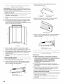
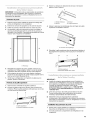
1.
Remove and save the literature package bag taped to the side
of the refrigerator and the parts bag behind the grille. Remove
the four brackets (two on each side) that attach the shipping
base to the refrigerator bottom.
NOTE: Do not remove tape and door bracing until the
refrigerator is in its final location.
2.
If necessary, reduce the tipping radius. See "Tipping Radius"
for ceiling height requirements or "Reduce Tipping Radius" for
step-by-step instructions. If you do not need to reduce the
tipping radius, proceed to "Move the Refrigerator into House."
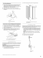
Before bringing the refrigerator into the home, be sure there is
adequate ceiling height to stand the refrigerator upright. See
"Tipping Radius" in the "Installation Requirements" section for
more information.
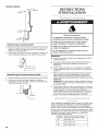
Ifyou do not have adequate ceiling height to stand the refrigerator
upright, the tipping radius can be reduced by removing the top
grille and side trims (see the following chart).
Model Reduced Tipping Radius
36 88" (223.5 cm)
42 881/2'' (224.8 cm)
48 891/4'' (226.7 cm)
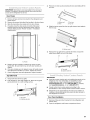
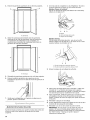
2.
Push the top grille straight up; then pull straight out. Lay the
grille on a soft surface.
B
3.
A. Top grifle
B. Cabinet side trim
Remove the six screws attaching each cabinet side trim to the
refrigerator and remove the side trims.
Tip Over Hazard
Refrigerator is top heavy and tips easily when not
completely installed.
Keep doors taped closed until refrigerator is
completely installed.
Use two or more people to move and install
refrigerator.
Failure to do so can result in death or serious injury.
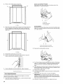
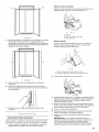
1.
Place an appliance dolly under the left side of the refrigerator
as shown. Place the corner posts from the packing materials
over the trims and handles as appropriate. Slowly tighten the
strap.
NOTE: Pass the dolly strap under the handles for the
Architect _Series.
[ r ]
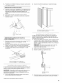
1. Grasp both ends of the top grille.
2. Place pieces of the shipping carton on the floor when rolling
the dolly and refrigerator into the house. Move the refrigerator
close to the built-in opening.
3. Place top of cardboard carton or plywood under refrigerator.
19

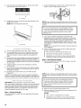
4. Stand the refrigerator up. First, place the left bottom edge of
the refrigerator on the floor, stand the refrigerator upright and
then lower the right-hand side of the refrigerator to the floor.
5. Reassemble the trim and top grille after the dolly has been
removed from the refrigerator.
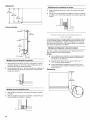
IMPO RTANT:
To avoid tipping during use, the solid soffit must be within
1" (2.5 cm) maximum above the refrigerator. If the solid soffit is
higher than 1" (2.5 cm) or one is not available, then the
refrigerator must be braced.
• It is recommended that board(s) be installed before the
refrigerator is installed.
• Board(s) must be long enough to fully cover the width of the
compressor cover.
• Locate the board(s) so the bottom surface(s) of the board(s)
is(are) 84" (213 cm) from the floor.
During installation, raise the refrigerator up so there is
V4"(6.35 mm) maximum between the top of the refrigerator
and the bottom of the anti-tip board(s). Do not crush the
compressor cover when raising the rear leveling legs.
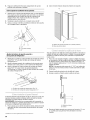
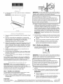
To Install Anti-tip Boards
1. Mark the stud locations on rear wall 80" to 90" (203 cm to
229 cm) above floor.
2. Securely attach one or two 2" x 4" x 32" (5 cm x 10 cm x
81 cm) boards to wall studs behind refrigerator. Use six
#8 x 3" (7.6 cm) (or longer) wood screws. The wood screws
must be screwed into the studs at least 11/2"(3.8 cm). The
board(s) must overlap the compressor cover.
A
2" (5 cm)
B
×
• •
D
A. Center board ¼" (6.35 mm) max. above refrigerator
B. Two 2" x 4" x 32" (5 cm x 10 cm x 81 cm) boards
C.Attach to studs with six #8 x 3" (7.6 cm) screws
D. Compressor cover
20
Read all directions before you begin.
IMPORTANT; If you turn the refrigerator on before the water line is
connected, turn the ice maker OFF.
Connect to Water Line
Parts Needed:
• Minimum 7 ft (2.13 m) flexible, codes approved water
supply line
Style I - Shutoff Valve Connection
NOTE: Ifyour water line connection does not look like Style 1, see
"Style 2 - Copper Line Connection."
1. Unplug refrigerator or disconnect power supply.
IMPORTANT: Before attaching the tubing to shutoff valve, flush
the main water supply line to remove particles and air in the water
line. Allow enough flow so that water becomes clear. Flushing the
water line may help avoid filters and/or water valves from
becoming clogged.
2. Connect the flexible, codes approved water supply line to the
water shutoff valve by threading the provided nut onto the
shutoff valve as shown.
NOTE: The shutoff valve shown is in the side cabinet as
recommended.
A
I/ III
B
C
3.
4.
A.Bulb
B.Nut
C. Watertubing
Place the end of the tubing into a bucket, and turn shutoff
valve ON.
Check for leaks. Tighten any nuts or connections (including
connections at the valve) that leak.
Style 2 - Copper Line Connection
NOTE: If there is a water supply line that meets the specifications
in "Water Supply Requirements," proceed to "Connecting to
Refrigerator." If not, use the following instructions to connect to
the household cold water supply.
1. Unplug refrigerator or disconnect power.
2. Turn OFF main water supply. Turn ON nearest faucet long
enough to clear line of water.
3. Locate a 1/2"to 1V4" (1.25 cm to 3.18 cm) vertical cold water
pipe near the refrigerator.
IMPORTANT:
4=
Make sure it is a cold water pipe.
Horizontal pipe will work, but drill on the top side of the
pipe, not the bottom. This will help keep water away from
the drill and keep normal sediment from collecting in the
valve.
Determine the length of copper tubing you need. Measure
from the connection on the lower left rear of refrigerator to the
water pipe. Add 7 ft (2.1 m) to allow for cleaning. Use V4"
(6.35 mm) O.D. (outside diameter) copper tubing. Be sure both
ends of copper tubing are cut square.
La page est en cours de chargement...
La page est en cours de chargement...
La page est en cours de chargement...
La page est en cours de chargement...
La page est en cours de chargement...
La page est en cours de chargement...
La page est en cours de chargement...
La page est en cours de chargement...
La page est en cours de chargement...
La page est en cours de chargement...
La page est en cours de chargement...
La page est en cours de chargement...
La page est en cours de chargement...
La page est en cours de chargement...
La page est en cours de chargement...
La page est en cours de chargement...
La page est en cours de chargement...
La page est en cours de chargement...
La page est en cours de chargement...
La page est en cours de chargement...
La page est en cours de chargement...
La page est en cours de chargement...
La page est en cours de chargement...
La page est en cours de chargement...
La page est en cours de chargement...
La page est en cours de chargement...
La page est en cours de chargement...
La page est en cours de chargement...
La page est en cours de chargement...
La page est en cours de chargement...
La page est en cours de chargement...
La page est en cours de chargement...
La page est en cours de chargement...
La page est en cours de chargement...
La page est en cours de chargement...
La page est en cours de chargement...
La page est en cours de chargement...
La page est en cours de chargement...
La page est en cours de chargement...
La page est en cours de chargement...
La page est en cours de chargement...
La page est en cours de chargement...
La page est en cours de chargement...
La page est en cours de chargement...
La page est en cours de chargement...
La page est en cours de chargement...
La page est en cours de chargement...
La page est en cours de chargement...
La page est en cours de chargement...
La page est en cours de chargement...
La page est en cours de chargement...
La page est en cours de chargement...
La page est en cours de chargement...
La page est en cours de chargement...
La page est en cours de chargement...
La page est en cours de chargement...
-
 1
1
-
 2
2
-
 3
3
-
 4
4
-
 5
5
-
 6
6
-
 7
7
-
 8
8
-
 9
9
-
 10
10
-
 11
11
-
 12
12
-
 13
13
-
 14
14
-
 15
15
-
 16
16
-
 17
17
-
 18
18
-
 19
19
-
 20
20
-
 21
21
-
 22
22
-
 23
23
-
 24
24
-
 25
25
-
 26
26
-
 27
27
-
 28
28
-
 29
29
-
 30
30
-
 31
31
-
 32
32
-
 33
33
-
 34
34
-
 35
35
-
 36
36
-
 37
37
-
 38
38
-
 39
39
-
 40
40
-
 41
41
-
 42
42
-
 43
43
-
 44
44
-
 45
45
-
 46
46
-
 47
47
-
 48
48
-
 49
49
-
 50
50
-
 51
51
-
 52
52
-
 53
53
-
 54
54
-
 55
55
-
 56
56
-
 57
57
-
 58
58
-
 59
59
-
 60
60
-
 61
61
-
 62
62
-
 63
63
-
 64
64
-
 65
65
-
 66
66
-
 67
67
-
 68
68
-
 69
69
-
 70
70
-
 71
71
-
 72
72
-
 73
73
-
 74
74
-
 75
75
-
 76
76


KitchenAid KSSS42QTB04 Guide d'installation
- Taper
- Guide d'installation
dans d''autres langues
Documents connexes
-
KitchenAid KSSC36QTS06 Guide d'installation
-
KitchenAid KSSO36FTX18 Guide d'installation
-
-
-
-
-
Whirlpool KSCS25FVBL02 Guide d'installation
-
Jenn-Air JCB2581WES00 Guide d'installation
-
-