
Installation Manual
For model N300X - a 2.7 cu. ft., 2-way or 3-way, refrigerator.
The models numbers of 3-way refrigerators contain “.3”. The model numbers of 2-way
refrigerators do not.
The letter “X” in the model number above, stands for a letter or a numeral which means a
refrigerator option.
NORCOLD, Inc.
P.O. Box 4248
Sidney, OH 45365-4248
Part No. 635403C (10/1/2014)
English
Improper installation, adjustment, alteration, service or maintenance can
cause injury or property damage. Refer to this manual. For assistance
or additional information, contact a qualied installer, service agency, or
the gas supplier.
FIRE OR EXPLOSION HAZARD
If you smell gas:
1. Open Windows
2. Do not attempt to light appliance.
3. Do not touch electrical switches.
4. Extinguish any open ame
5. Shut off fuel supply.
6. Evacuate immediately and call emergency services.
Failure to follow these instructions could result in re or explosion, which could cause
property damage, personal injury, or death.
FOR YOUR SAFETY
Do not store or use gasoline or other ammable vapors and liquid in the
vicinity of this or any other appliance.
WARNING
!
WARNING
!
Norcold Customer Support Dept.
Telephone: 800-543-1219
Fax: 734-769-2332
Web Site: www.norcold.com

Installation Manual 2
Table of Contents
Safety Awareness ..................................................................................................................................................................................... 2
Safety Instructions ....................................................................................................................................................................................2
Certication and Code Requirements.......................................................................................................................................................3
Ventilation Requirements..........................................................................................................................................................................4
Assemble the Enclosure .......................................................................................................................................................................... 4
Install the Lower and Upper Vents............................................................................................................................................................5
Install the Refrigerator ..............................................................................................................................................................................7
Installation Options ...................................................................................................................................................................................7
Install the decorative door panel .......................................................................................................................................................7
Reverse the door swing.....................................................................................................................................................................8
Connect the Electrical Components .........................................................................................................................................................8
Connect the 120 volts AC supply ......................................................................................................................................................8
Connect the 12 volts DC supply (3-way models only) .......................................................................................................................8
Connect the Propane Gas Components.................................................................................................................................................10
Connect the gas supply system ......................................................................................................................................................10
Examine the gas supply system for leaks ....................................................................................................................................... 11
Safety Instructions
Safety Awareness
Read this manual carefully and understand the contents before you install the refrigerator.
Be aware of possible safety hazards when you see the safety alert symbol on the refrigerator and in this manual. A signal word follows
the safety alert symbol and identies the danger of the hazard. Carefully read the descriptions of these signal words to fully know their
meanings. They are for your safety.
This signal word means a hazard, which if ignored, can cause dangerous personal injury, death, or much
property damage.
This signal word means a hazard, which if ignored, can cause small personal injury or much property
damage.
- This refrigerator is not approved for use as a free standing refrigerator. It is equipped for the use of propane gas only
and can not be changed to use any other fuels (natural gas, butane, etc.).
- Incorrect installation, adjustment, alteration, or maintenance of this refrigerator can cause personal injury, property
damage, or both.
- Obey the instructions in this manual to install the intake and exhaust vents.
- Do not install the refrigerator directly on carpet. Put the refrigerator on a metal or wood panel that extends the full
width and depth of the refrigerator.
- Do not allow anything to touch the refrigerator cooling system.
- Propane gas can ignite and cause an explosion that can result in property damage, personal injury, or death. Do not
smoke or create sparks while working on the gas supply system. Do not use an open ame to examine the gas supply
piping or ttings for leaks. Always use two wrenches to tighten or loosen the propane gas supply line connections.
CAUTION
!
WARNING
!
WARNING
!

Installation Manual 3
- Make sure the electrical installation obeys all applicable codes. See “Certication and Code Requirements” section.
- Do not bypass or change the refrigerator’s electrical components or features.
- Do not spray liquids near electrical outlets, connections, or the refrigerator components. Many liquids are electrically
conductive and can cause a shock hazard, electrical shorts, and in some cases re.
- The refrigerator cooling system is under pressure. Do not try to repair or to recharge a defective cooling system.
- The cooling system contains sodium chromate. The breathing of certain chromium compounds can cause cancer. The
cooling system contents can cause severe skin and eye burns, and can ignite and burn with an intense ame. Do not
bend, drop, weld, move, drill, puncture, or hit the cooling system.
- The rear of the refrigerator has sharp edges and corners. To prevent cuts or abrasions when working on the
refrigerator, use caution and wear cut resistant gloves.
Certication and Code Requirements
This refrigerator is certied by CSA International as meeting the
latest edition of ANSI Z21.19 / CSA 1.4 standards for installation
in mobile homes or recreational vehicles.
The refrigerator must be installed in accordance with this
“Installation Manual” in order for the Norcold limited warranty
to be in effect. In addition, the installation must conform to the
following, as applicable:
In the United States and Canada:
- Local codes, or in the absence of local codes, the National
Fuel Gas Code, ANSI Z223.1/NFPA 54, the Natural Gas and Propane installation Code, CSA B149.1, ANSI A119.2 Recreational
Vehicles Code, and CSA Z240 RV Series, Recreational Vehicles.
- A manufactured home (mobile home) installation must conform with the Manufactured Home Construction and Safety Standard,
Title 24 CFR, Part 3280 [formerly the Federal Standard for Mobile Home Construction and Safety, Title 24 (part 280), and the
current CSA Z240.4, Gas-equipped Recreational Vehicles and Mobile Housing.
- If an external power source is utilized, the appliance, when installed, must be electrically grounded in accordance with local codes
or, in the absence of local codes, the National Electrical code, and ANSI/NFPA 70, or the Canadian Electrical Code, CSA C22.2.
Parts 1 and 2.
All propane gas supply piping and ttings must obey local, state, and national codes about type and size. These components must also
obey the current NFPA 501C section 2-4, and in Canada with the current CAN 1-6.10 Standard.
CAUTION
!
Art01290

Installation Manual 4
Ventilation Requirements
The completed installation must:
- Make sure there is sufcient intake of fresh air for combustion.
- Make sure the living space is completely isolated from the combustion system of the refrigerator.
- Make sure there is complete and unrestricted ventilation of the ue exhaust which, in gas mode, can produce carbon
monoxide. The breathing of carbon monoxide fumes can cause dizziness, nausea, or in extreme cases, death.
- Make sure the refrigerator is completely isolated from its heat generating components through the correct use of bafes
and panel construction.
Certied installation needs one lower intake vent and one upper exhaust vent. Install the upper exhaust vent either through the roof or
through the side wall of the vehicle exactly as written in this manual. Any other installation method voids both the certication and the
factory warranty of the refrigerator.
The bottom of the opening for the lower intake vent, which is also the service access door, must be even with or immediately below the
oor level. This allows any leaking propane gas to escape to the outside and not to collect at oor level.
CSA International certication allows the refrigerator to have zero (0) inch minimum clearance at the sides, rear, top, and bottom. While
there are no maximum clearances specied for certication, the following maximum clearances are necessary for correct refrigerator
performance:
Bottom 0 inch min. 0 inch max.
Each Side 0 inch min 1/4 inch max.
Top 0 inch min. 1/4 inch max.
Rear 0 inch min. 1 inch max.
These clearances plus the lower and upper vents cause the natural air draft that is necessary for good refrigeration. Cooler air
comes in through the lower intake vent, goes up around the refrigerator coils where it removes the excess heat from the refrigerator
components, and goes out through the upper exhaust vent. If this air ow is blocked or decreased, the refrigerator will not cool
correctly.
Each NORCOLD model is certied by CSA International for correct ventilation. Install only the certied vents that are listed in this
manual.
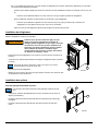
Assemble the Enclosure
1. Make sure the enclosure is 29.75 - 29.88 inches high x 20.50 - 20.63 inches wide x 21.38 inches deep.
2. Make sure the oor is solid and level.
- The oor must be metal or a wood panel and extend the full width and depth of the enclosure.
- The oor must be able to support the weight of the refrigerator and its contents.
3. Make sure there are no adjacent heat sources such as a furnace vent, a hot water heater vent, etc.
4. If there is more than 1/2 inch between either side of the refrigerator and the inside of the enclosure:
- Fill the space with berglass (batt-type) insulation or add a bafe to eliminate the clearance.
- The rear of the batt-type insulation must be between 14 -15 inches from the face of the enclosure.
- Securely attach the batt-type insulation to the enclosure, so that it remains in this position during refrigerator installation, if it
becomes wet, and in windy conditions.
WARNING
!

Installation Manual 5
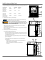
Install the Lower and Upper Vents
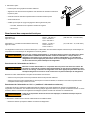
1. Using the following chart, decide which vents and rough opening (RO) sizes to use.
Certied Vent P/N RO Height RO Width
Upper Roof 622293 24 in. 5 1/4 in.
Exhaust Vent
Upper Side 617485 7 1/4 in. 18 in.
Exhaust Vent
Lower Side 617484 9 3/4 in. 19 3/8 in.
Intake Vent
Universal Upper 620505 6 3/16 in. 17 15/16 in.
and Lower Vent
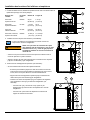
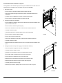
2. Install the lower intake vent (See Art01629):
The lower intake vent is also the service access opening for the
components on the rear of the refrigerator.
Make sure the bottom of the opening of the lower intake
vent is even with or immediately below the oor level. This
allows any leaking propane gas to escape to the outside
and not to collect at oor level.
- Make sure the bottom of the opening of lower intake vent is even with or
immediately below the oor level.
- Align the lower intake vent [9] vertically below the coils [10] and the condenser
[11] of the refrigerator.
3. Install the upper exhaust vent (see Art01630):
- If you install the upper side exhaust vent:
- Make sure the distance [25] from the bottom of the enclosure to the top of
the rough opening for the upper exhaust vent is at least 37 inches or poor
cooling performance can occur.
- Align the upper exhaust vent [24] horizontally above the lower intake vent
[9] of the refrigerator.
- Install a bafe [13] to prevent stagnant hot air in the area [14] above
the refrigerator.
- Make sure there is less than 1/4 inch clearance [15] between the
bafe and the top of the refrigerator.
- Make sure the bafe is the full width of the inside of the
enclosure.
Art02422
13
17
25
14
17
15
290
191
11
NOTICE
WARNING
!
Art01629
9
10
11
Art01630
14
13
15
9
24
25
17
191
17

Installation Manual 6
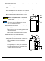
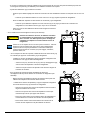
- If the construction of the vehicle does not allow the distance [25] to be 37 inches, the distance (optional only) can be as little as
30 3/4 inches (See Art02422) if you:
- Add two bafes [17] to the rear of the enclosure:
- Make sure the distance [290] from the bottom of the enclosure to the top of the lower bafe is between 10 and 10 1/2
inches.
- Make sure the lower bafe is between 1/4 and 1/2 inch [191] from the coils of the refrigerator.
- Put the upper bafe at the lower edge of the condenser [11] of the refrigerator.
- Make sure the upper bafe is between zero (0) and 1/4 inch [15] below and zero (0) and 1/4 inch away from the
condenser of the refrigerator.
- Make sure both bafes are the full width of the inside of the enclosure.
- If you install the roof exhaust vent (See Art01631):
Make sure that no sawdust, insulation, or other construction
debris is on the refrigerator or in the enclosure. Debris can
cause a combustion hazard and prevent the refrigerator from
operating correctly.
Tighten the screws of the roof cap to 10 inch-pounds max. Also make
sure that the air ow around the upper roof exhaust cap is not blocked
or decreased by other roof mounted features such as a luggage
carrier, an air conditioner, a solar panel, etc.
- If the design of the vehicle allows, install the roof exhaust vent [12] directly
above the condenser [11] of the refrigerator.
- Install a bafe [13] to prevent stagnant hot air in the area [14] above the
refrigerator.
- Make sure there is less than 1/4 inch clearance [15] between the bafe
and the top of the refrigerator.
- Make sure the bafe is the full width of the inside of the enclosure.
- If the design of the vehicle does not allow you to install the roof exhaust vent
directly above the condenser of the refrigerator (See Art01632):
- Align the roof exhaust vent [12] above the lower intake vent and move it
inboard as necessary.
- Install two bafes [172] to prevent stagnant hot air in the area [14] above
the refrigerator.
- Make sure both bafes are the full width of the inside of the
enclosure.
- Make sure that both bafes are no more than 45° from vertical.
- Put one bafe between the top rear edge of the refrigerator and the
inside edge of the upper exhaust vent opening.
- Put the other bafe between the outside edge of the upper exhaust
vent opening and the side wall of the vehicle.
Art01631
14
13
12
15
11
Art01632
14
172
12
172
11
17
17
9
15
191
290
CAUTION
!
NOTICE

Installation Manual 7
- If there is more than 1 inch of clearance between the rear of the refrigerator and the enclosure, add two bafes [17] to the rear
of the enclosure (See Art01630 and Art01632):
- Make sure the distance [290] from the bottom of the enclosure to the top of the lower bafe is between 10 and 10 1/2
inches.
- Make sure the lower bafe is between 1/4 and 1/2 inch [191] from the coils of the refrigerator.
- Put the upper bafe at the lower edge of the condenser [11] of the refrigerator.
- Make sure the upper bafe is between zero (0) and 1/4 inch [15] below and zero (0) and 1/4 inch away from the
condenser of the refrigerator.
- Make sure both bafes are the full width of the inside of the enclosure.
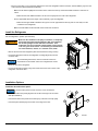
Install the Refrigerator
Put the refrigerator in position (see Art01253):
Make sure the combustion seal [28] is not broken, is completely
around the refrigerator mounting anges [156], and is between
the mounting anges and the wall of the enclosure. If the
combustion seal is not complete, exhaust fumes can be present
in the living area of the vehicle. The breathing of exhaust fumes
can cause dizziness, nausea, or in extreme cases, death.
- Remove the door from the refrigerator (See “Reverse the door swing” section).
- Put screws through the holes of the refrigerator mounting anges and into the
enclosure wall.
To avoid bending the breaker, make sure that the screws are
perpendicular to the breaker and do not overtighten the screws.
- Attach the door to the refrigerator.
- Put a screw through the holes [121] in the braces at the lower rear corners of the
refrigerator and into the oor.
28
156
Art01253
121
Installation Options
Install the decorative door panel:
The decorative panels must be 3/16 inch or less in thickness.
- Make a decorative door panel [38] that is 25 15/16 inches high x 20 1/8 inches
wide (See Art00977).
- Push the decorative door panel into the slots [157] of the door end caps [158].
- Push each panel retainer [37] into the slot on the edge of the door.
Art00977
38
158
37
157
NOTICE
NOTICE
WARNING
!

Installation Manual 8
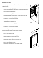
Reverse the door swing:
This refrigerator has door hinges that allow you to change the direction that the door opens
by moving the hinges to the opposite corner (See Art00981).
1. Remove the door:
- Turn out and save the upper hinge pin [63].
- Open the door a small amount and pull the top of the door away from the upper hinge of
the refrigerator.
- Lift the door off of the lower hinge pin [64].
- Turn out and save the lower hinge pin.
2. Change the position of the hinges:
- Remove and save the plastic bushings that are in the holes on the ends of the door.
- Remove the screws from the upper hinge [159].
- Put this hinge on the other side as the lower hinge.
- Attach the hinge with the screws.
- Turn the lower hinge pin down into this hinge.
- Remove the screws from the lower hinge [160].
- Remove the screw from the travel latch [161].
- Put this hinge on the other side as the upper hinge.
- Attach the hinge with the screws.
- Push the bushings into the empty holes in the ends of the door.
3. Change the position of the travel latch (See Art00978 and Art00979):
- Put the travel latch on the other side of the refrigerator.
- Attach the travel latch with the screw.
- Remove the screw from the travel latch plate [162] on the door.
- Pull each hinge bushing [74] out of the hole in the door.
- Pull the plastic plug out of the top of the door.
- Push the plastic plug into the other hole in the top of the door.
- Put the travel latch plate on the other side of the door.
- Attach the travel latch plate with the screw.
- Push each hinge bushing into the hole on the other side of the door.
63
Art00981
159
160
161
64
74
162
74
Art00978

Installation Manual 9
161
166
162
Art00979
4. Install the door:
- Put the door down onto the lower hinge pin.
- Align the holes in the upper hinge and the hinge bushing and hold in this position.
- Screw the upper hinge pin down into the upper hinge and into the door.
- Tighten all of the screws.
- Make sure the travel latch engages the travel latch plate.
- If not, loosen the screw and adjust the height of the travel latch plate.
- Tighten the screw.
Connect the Electrical Components
AC Operation 120 volts AC voltage (108 volts min. - 132 volts max.)
Current Draw 1.4 Amps at 110 Volts AC
1.5 Amps at 120 Volts AC
DC Operation (3-way models only) 12 volts DC voltage (11.5 volts min. - 15.4 volts max.)
Current Draw 12 Amps at 12 Volts DC
14 Amps at 14 Volts DC
This refrigerator operates on these electrical sources. Operation out of these limits may damage the refrigerator’s electrical circuit parts
and will void the warranty.
The rear of the refrigerator cooling system has hot surfaces and sharp surfaces that can damage electrical
wiring. Make sure that there is a good clearance between all electrical wiring and the cooling system of the
refrigerator. Position any electrical wiring within the refrigerator enclosure opposite the burner side of the
refrigerator. Do not put any electrical wiring through the roof exhaust vent. Failure to correctly position
electrical wiring can result in electrical shock or re.
Connect the 120 volts AC supply:
Connect the AC power cord only to a grounded three-prong receptacle. Do not remove the round ground
prong from the power cord. Do not use a two-prong adapter or an extension cord. Operation of the
refrigerator without correct ground can cause dangerous electrical shock or death if you are touching the
metal parts of the refrigerator.
Put the AC power cord into a grounded three-prong receptacle:
- Make sure the receptacle is positioned within easy reach of the lower intake vent.
- Make sure the power cord does not touch the burner cover, the ue pipe, or any hot component that could damage the insulation of
the power cord.
Connect the 12 volts DC supply (3-way models only):
As the distance from the vehicle battery to the refrigerator increases, the correct AWG wire size and fuse size also increases. If the
wire size is too small for the distance, a voltage drop occurs. The voltage drop decreases the output of the system heater and causes
decreased cooling performance.
If you use an incorrect wire size and/or fuse size, electrical re can result.
1. Determine the min. wire size and the max. fuse size to use:
- Measure the distance from the vehicle battery to the refrigerator:
WARNING
!
WARNING
!
WARNING
!

Installation Manual 10
219
Art01254
165
218
Connect the Propane Gas Components
This refrigerator operates on propane gas at a pressure of 11 inches Water Column Propane.
Connect the propane gas supply system:
Be very careful when working on or near the propane gas system.
- Do not smoke or use an open ame near the propane gas system.
- Do not use an open ame to examine for leaks.
- Do not connect the refrigerator to the gas tank without a pressure regulator between them.
- To avoid an propane gas leak, always use two wrenches to tighten or loosen the gas supply line connections.
- Leaking propane gas can ignite or explode and result in dangerous personal injury or death.
Connect the gas supply line to the refrigerator:
- Make sure all tubing and ttings obey all local, state, and national codes about size and type.
- Make sure that all exible metal connectors obey the current CAN1-6.10 Standard.
- Make sure that the materials used for the gas supply line obey both the current NFPA 1192 and CSA Z240 Standards on
Recreational Vehicles. Norcold recommends the use of 3/8 inch copper tubing as the gas supply line and requires a 3/8 inch SAE
(UNF 5/8-18) female are tting as the connection to the refrigerator.
- If the distance is 0 - 20 feet, use a minimum of 12 AWG wire and a maximum 20 amp fuse.
- If the distance is more than 20 feet, use a minimum 10 AWG wire and a maximum 30 amp fuse.
- If the wire size is larger than the min. size, use the correct fuse per RVIA A119.2 standard or local codes.
The wire connections must be clean, tight and free of corrosion. If any of these items are not correct:
- A voltage drop to the refrigerator will occur.
- The voltage drop will reduce the cooling performance of the refrigerator.
The terminals for connecting the DC power supply are marked positive (+) and negative (-) on the terminal block of the refrigerator.
Make sure that:
- Each DC power supply wire is attached to the correct polarity terminal.
- The chassis or the vehicle frame is not used as one of the conductors.
- The DC power supply wires including the fuses are routed directly from the battery
to the refrigerator.
2. Connect the D.C. power supply wires:
- Attach a 1/4 inch female Quick Connect terminal to each DC power supply wire.
- Push each power wire onto the terminal block [219] at the rear of the refrigerator
(See Art01254).
- Make sure each DC power supply wire is on the correct polarity terminal.
WARNING
!

Installation Manual 11
- Put the propane gas supply line up through the oor of the enclosure.
- Make sure the hole through the oor is large enough to allow clearance for the gas supply line.
- Put a weather resistant seal (grommet, sealant, etc.) around the gas supply line where it goes through the oor to prevent vibration
and abrasion.
- To prevent vibration and abrasion, make sure that the gas supply line is not against anything in the enclosure.
- Attach the gas supply line to the bulkhead ting [2] of the refrigerator (See Art01254).
Examine the gas supply system for leaks:
Do not allow the leak detecting solution to touch the electrical components. Many liquids are electrically
conductive and can cause a shock hazard, electrical shorts, and in some cases, re.
Use a leak detecting solution to examine the gas supply line and all propane gas connections for leaks.
If you use compressed air for the test:
- The pressure at the manual shut off valve of the refrigerator must not be more than 1/2 psig (14 inches Water Column).
- If the air pressure is more than 1/2 psig (14 inches Water Column), remove the gas supply line from the bulkhead tting of the
refrigerator before the test.
- If the air pressure is equal to or less than 1/2 psig (14 inches Water Column), close the manual shutoff valve of the refrigerator
before the test.
WARNING
!

Installation Manual 12

Manuel d’installation
pour le modèle N300X, réfrigérateur de 2,7 pi3 à 2 ou 3 alimentations
Les numéros de modèle des réfrigérateurs à triple alimentation contiennent « .3 », mais pas
ceux des réfrigérateurs à double alimentation.
La lettre « X », dans les numéros de modèle ci-dessus, représente une lettre ou un chiffre
correspondant à une option de réfrigérateur.
NORCOLD, Inc.
P.O. Box 4248
Sidney, OH 45365-4248 - E.-U.A.
Réf. 635403C (10/1/2014)
Français
Norcold Customer Support Dept.
Telephone; 800-543-1219
Fax: 937-497-3183
Web Site: www.norcold.com
Une faute d’installation, de réglage, de modication, de
réparation ou d’entretien peut causer des préjudices corporels
ou matériels. Se reporter à ce manuel. Pour obtenir de
l’assistance ou des informations supplémentaires, s’adresser
à un installateur qualié, au service après-vente ou à la
compagnie de gaz
AVERTISSEMENT
!
RISQUE Dʼ INDENDDIE OU DʼEXPLOSION
Si vous sentez une odeur de gaz:
1. Ouvrez les fenêtres.
2. teignez toute ame nue..
3. Ne pas toucher les interrupteurs électiques.
4. teignez toute ame nue..
5. Coupez Iˊ alimentation en combustible.
6. vacuez immédiatement et applez les services dˊurgence
Ne pas suivre ces instructions peut provoquer in incendie ou un explosion, pouvant causer
des dommages matériels, des blessures ou la mort.
AVERTISSEMENT
!
SÉCURITÉ PERSONNELLE
Ne pas conserver ni utiliser d’essence ou d’autres liquides
inammables, ou dont les vapeurs peuvent s’enammer, à proximité de
cet appareil ou de tout autre appareil électroménager.
NE PAS installer ce réfrigérateur sous le pont dans un bateau. Ne pas installer ce réfrigérateur
dans une cabine xe ou autre zone habitable intérieure. Pour fonctionner correctement et sans
danger, ce réfrigérateur doit utiliser uniquement un système à prise d’air extérieur et à ventilation
aspirante conçu et agréé par NORCOLD. Toute autre méthode de ventilation pourrait libérer des
gaz d’échappement à combustion mortels et (ou) des fumées explosives de gaz propane dans la
zone habitable et (ou) sous le pont.
AVERTISSEMENT
!

Manuel d’installation 2
Table des matières
Questions de sécurité ............................................................................................................................................................................. 14
Consignes de sécurité ............................................................................................................................................................................15
Certication et exigences réglementaires...............................................................................................................................................16
Exigences de ventilation ......................................................................................................................................................................... 16
Exigences relatives à l’enceinte ............................................................................................................................................................17
Installation des bouches d’air .................................................................................................................................................................17
Installation du réfrigérateur ..................................................................................................................................................................... 20
Installation des options ...........................................................................................................................................................................20
Pose des panneaux décoratifs de porte ..........................................................................................................................................20
Inversion du sens d’ouverture de la porte .......................................................................................................................................20
Branchement des composants électriques.............................................................................................................................................22
Branchement de l’alimentation 120 V c.a. .............................................................................................................................................. 22
Branchement de l’alimentation 12 V c.c. (modèles 3 alim. seulement) ...........................................................................................22
Raccordement des composants du système de propane ......................................................................................................................23
Raccordement du système d’alimentation en gaz...........................................................................................................................23
Détection des fuites du système d’alimentation en gaz ..................................................................................................................24
Consignes de sécurité
Questions de sécurité
Veuillez lire attentivement ce manuel an de vous familiariser avec son contenu avant de faire fonctionner le réfrigérateur.
Soyez très prudent lorsque vous apercevez le symbole de sécurité sur le réfrigérateur ou dans ce manuel. Le mot adjacent au symbole
de sécurité précise la gravité du danger. Lisez attentivement la dénition de ces dangers donnée ci-dessous. Il y va de votre sécurité.
Ce terme de signalement indique un danger qui, s’il n’est pas pris en compte, peut causer une
blessure grave, la mort ou d’importants dégâts matériels.
Ce terme de signalement indique un danger qui, s’il n’est pas pris en compte, peut causer une blessure
légère ou d’importants dégâts matériels.
- Ce réfrigérateur n’est pas destiné à servir de réfrigérateur amovible. Il est conçu pour fonctionner au gaz propane
seulement et ne peut pas être modié pour utiliser d’autres carburants (gaz naturel, butane, etc.).
- Une faute d’installation, de réglage, de modication ou d’entretien de ce réfrigérateur peut causer des préjudices
corporels et (ou) matériels.
- Observer les consignes de ce manuel pour installer les bouches de ventilation (prise d’air et échappement).
- Ne pas installer le réfrigérateur à même une moquette ou un tapis. Le placer sur un panneau de métal ou de bois
s’étendant au moins sur toute sa largeur et toute sa profondeur.
- Ne pas laisser quoi que ce soit toucher le système frigorique du réfrigérateur.
- Le gaz propane est susceptible de s’enammer et de causer une explosion et, par conséquent, des dégâts matériels et
des blessures graves ou mortelles. Ne pas fumer ni faire d’étincelles lors de l’intervention sur le système d’alimentation
en gaz. Ne pas se servir d’une amme nue pour rechercher les fuites au tuyau ou aux raccords d’arrivée de gaz. Toujours
se servir de deux clés pour serrer ou desserrer les raccords du tuyau d’arrivée de gaz propane.
ATTENTION
!
AVERTISSEMENT
!
AVERTISSEMENT
!

Manuel d’installation 3
- S’assurer de la conformité de l’installation électrique à tous les codes applicables. Voir la section « Certication et codes
à respecter ».
- Ne pas contourner ou modier les composants ou fonctions électriques du réfrigérateur.
- Ne pas vaporiser de liquides près des prises électriques, des raccords ou des pièces du réfrigérateur. Nombre de
liquides sont conducteurs et peuvent poser des risques de décharge électrique, de court-circuit, voire même d’incendie.
- Le système frigorique du réfrigérateur est sous pression. Ne pas essayer de réparer ou recharger un système
frigorique défectueux.
- Le système frigorique contient du chromate de sodium. L’inhalation de certains composés du chrome peut causer le
cancer. Le système frigorique contient des produits chimiques qui peuvent causer de graves brûlures à la peau et aux
yeux, s’enammer et brûler avec une amme intense. Ne pas recourber, faire tomber, souder, déplacer, percer, perforer
ou heurter le système frigorique.
- L’arrière du réfrigérateur présente des arêtes vives et des coins anguleux. Pour éviter de se couper ou de s’écorcher lors
du travail sur le réfrigérateur, faire attention et porter des gants résistant aux coupures.
Certication et exigences réglementaires
Ce réfrigérateur est homologué par la section International de
l’ACNOR comme conforme à la dernière édition des normes
ANSI Z21.19 / CSA 1.4 en ce qui concerne l’installation dans des
caravanes résidentielles ou véhicules de loisir.
Pour que la garantie limitée Norcold puisse entrer en vigueur,
l’installation du réfrigérateur doit être conforme au présent
« Manuel d’installation ». De plus, elle doit respecter les
éléments suivants, lorsqu’ils sont applicables :
Aux États-Unis et au Canada :
- Les codes locaux, ou, à défaut, le code National Fuel Gas Code, les normes ANSI Z223.1/NFPA 54, le code Natural Gas and
Propane installation Code, la norme CSA B149.1, le code ANSI A119.2 Recreational Vehicles Code et les normes CSA Z240 RV
Series, Recreational Vehicles.
- L’installation des maisons préfabriquées (caravanes résidentielles) doit se conformer à la norme Manufactured Home Construction
and Safety Standard, titre 24 CFR, partie 3280 [anciennement dénommée Federal Standard for Mobile Home Construction and
Safety, titre 24 (partie 280), et à la norme à jour CSA Z240.4, Gas-equipped Recreational Vehicles and Mobile Housing.
- Si une source d’alimentation externe est employée, l’appareil électroménager doit, à son installation, faire l’objet d’une mise à la
terre électrique conforme aux codes locaux ou, à défaut de tels codes, conforme au code National Electrical code et aux normes
ANSI/NFPA 70, ou au Code canadien d’électricité, CSA C22.2. parties 1 et 2.
Tous les tuyaux et raccords d’arrivée de gaz propane doivent respecter les codes locaux, provinciaux et fédéraux s’appliquant à leurs
types et dimensions. Ces éléments doivent également être conformes à la norme à jour NFPA 501C section 2-4, et, au Canada, à la
norme à jour CAN 1-6.10.
Art01290
ATTENTION
!

Manuel d’installation 4
Exigences relatives à l’enceinte
1. L’enceinte doit avoir 29,75 - 29,88 po de hauteur sur 20,50 - 20,63 po de largeur sur 21,38 po de profondeur.
2. Le plancher doit être solide et de niveau.
- Le plancher doit être un panneau en métal ou en bois de toute la largeur et de toute la profondeur de l’enceinte.
- Le plancher doit pouvoir soutenir le poids du réfrigérateur et de son contenu.
3. S’assurer qu’il n’y a pas de sources de chaleur adjacentes, telles que bouches de ventilation de chauffage ou de chauffe-eau.
4. S’il y a plus de 1/2 po entre un côté du réfrigérateur et l’intérieur de l’enceinte :
- Remplir l’espace d’isolant (en natte) en bre de verre ou ajouter un déecteur pour éliminer le dégagement.
- L’arrière de l’isolant en natte doit être entre 14 et 15 po de la face de l’enceinte.
- Bien xer l’isolant en natte à l’enceinte de façon à ce qu’il reste dans cette position durant l’installation du réfrigérateur, s’il
devient mouillé et s’il y a du vent.
Exigences de ventilation
Conditions à satisfaire par l’installation :
- Il doit y avoir un apport d’air frais sufsant pour la combustion.
- L’espace de séjour doit être complètement isolé du système de combustion du réfrigérateur.
- Le conduit de fumée d’échappement doit bénécier d’une ventilation totale et sans restriction car, en mode de
fonctionnement au gaz, du monoxyde de carbone peut en sortir. L’inhalation de fumées contenant du monoxyde de
carbone peut causer des vertiges, des nausées ou, dans les cas extrêmes, la mort.
- S’assurer de l’isolation complète du réfrigérateur par rapport à ses composants produisant de la chaleur en utilisant un
jeu approprié de déecteurs et de panneaux.
Pour réaliser l’installation certiée, il faut installer une bouche de prise d’air inférieure et une bouche de sortie supérieure. On installera
la bouche de sortie supérieure soit par le toit, soit par la paroi latérale du véhicule, de manière conforme en tous points aux instructions
contenues dans le présent manuel. Toute autre méthode d’installation annule la certication et la garantie usine du réfrigérateur.
L’ouverture de la bouche de prise d’air inférieure, qui sert aussi de point d’accès pour l’entretien, doit être au niveau du plancher
ou juste en dessous. En cas de fuite, cette conguration permet au propane de ne pas s’accumuler au niveau du plancher et de
s’échapper à l’extérieur.
En vertu de l’homologation de la section International de l’ACNOR, il peut y avoir un dégagement nul sur les côtés, l’arrière, le haut
et le bas du réfrigérateur. Alors qu’aucun dégagement maximum n’est spécié par l’homologation, le réfrigérateur ne peut fonctionner
correctement que si les dégagements maximum suivants sont respectés :
Bas 0 po minimum 0 po maximum
Côtés 0 po minimum 1/4 po maximum
Haut 0 po minimum 1/4 po maximum
Arrière 0 po minimum 1 po maximum
Le respect de ces dégagements et la présence des bouches d’air inférieure et supérieure assurent le tirage d’air naturel nécessaire
pour assurer une bonne réfrigération. L’air frais pénètre par la bouche de prise d’air inférieure, monte autour du serpentin de
réfrigération où il extrait l’excès de chaleur des composants du réfrigérateur, et s’échappe par la bouche de sortie supérieure. Si cette
circulation de l’air est bloquée ou limitée, le réfrigérateur ne refroidit pas correctement.
Le système de ventilation de chaque modèle NORCOLD est homologué par la section International de l’ACNOR. Installer uniquement
les bouches de ventilation homologuées qui sont spéciées dans ce manuel.
AVERTISSEMENT
!

Manuel d’installation 5
Installation des bouches d’air inférieure et supérieure
1. À l’aide du tableau suivant, déterminez quelles bouches d’air vous devez utiliser et
quelles découpes (D) vous devez pratiquer.
Bouche d’air N° de RO Hauteur D Largeur D
certiée pièce
Sortie d’air 622293 24 po/ 5 1/4 po
supérieure de toit (60,96 cm) (13,33 cm)
Sortie d’air 617485 7 1/4 po/ 18 po
supérieure latérale (18,41 cm) (45,72 cm)
Prise d’air 617484 9 3/4 po/ 19 3/8 po
inférieure latérale (24,76 cm) (49,21 cm)
Sortie d’air, universel, 620505 6 3/16 po 17 15/16 po
supérieur et inférieur (15,71cm) (45,56 cm)
2. Installez la bouche de prise d’air inférieure (voir Art01629) :
La prise d’air inférieure sert également d’ouverture d’accès aux
composants à l’arrière du réfrigérateur.
Veiller à ce que le bas de l’ouverture de la prise
d’air inférieure soit de niveau avec le sol, ou juste
en dessous. Ainsi, s’il y a fuite du gaz propane, il
s’échappe à l’extérieur au lieu de s’accumuler au
niveau du sol.
- Assurez-vous que l’ouverture de la bouche de prise d’air inférieure soit au
niveau du plancher ou juste en dessous.
- Alignez la bouche de prise d’air inférieure [9] à la verticale sous le serpentin
[10] et le condensateur [11] du réfrigérateur.
3. Poser la bouche d’échappement supérieure (voir Art01630) :
- Si vous installez la bouche de sortie supérieure latérale :
- S’assurer que la distance [25] entre le bas de l’enceinte et le haut de
la découpe de la bouche d’échappement supérieure est d’au moins 37
inches, sinon on risque d’obtenir un mauvais refroidissement.
- Aligner la bouche d’échappement supérieure [24] à l’horizontale au-
dessus de la prise d’air inférieure [9] du réfrigérateur.
- Installez une cloison de séparation [13] pour empêcher la stagnation
d’air chaud dans la zone [14] au-dessus du réfrigérateur (voir
Art01249).
- Assurez-vous qu’il y ait moins de 1/4 po (0,63 cm) de
dégagement [15] entre la cloison de séparation et le haut du
réfrigérateur.
- Assurez-vous que la cloison de séparation soit de toute la
largeur de l’intérieur de l’enceinte.
Art01629
9
10
11
AVIS
AVERTISSEMENT
!
Art02422
13
17
25
14
17
15
290
191
11
Art01630
14
13
15
9
24
25
17
191
17

Manuel d’installation 6
- Si, de par la construction du véhicule, la distance [24] ne peut pas être de 37 inches, elle peut être réduite jusqu’à 30 3/4
inches (option uniquement) (voir Art02422) si les conditions suivantes sont remplies :
- Ajouter deux déecteurs [17] à l’arrière de l’enceinte :
- S’assurer que la distance [290] entre le bas de l’enceinte et le haut du déecteur inférieur est comprise entre 10 et 10 1/2
po.
- S’assurer que le déecteur inférieur se trouve entre 1/4 et 1/2 po [191] des serpentins du réfrigérateur.
- Placer le déecteur supérieur au bord inférieur du condenseur [11] du réfrigérateur.
- S’assurer que le déecteur supérieur se trouve entre zéro (0) et 1/4 po [15] au-dessous du condenseur du
réfrigérateur et à une distance de zéro (0) à 1/4 po de ce condenseur.
- Veiller à ce que les deux déecteurs fassent toute la largeur de l’intérieur
de l’enceinte.
- Si l’on installe la bouche d’échappement de toit (voir Art01631) :
S’assurer de l’absence de sciure, de matériau d’isolation
ou d’autres débris de construction sur le réfrigérateur ou
dans l’enceinte. Les débris peuvent poser un danger de
combustion et empêcher le fonctionnement correct du
réfrigérateur.
Serrez les vis du chapeau de toit à 10 livres-pounce maximum. S’assurer
également que l’écoulement d’air autour de la came d’échappement
supérieure de toit n’est pas partiellement ou totalement restreint par
d’autres articles montés sur le toit tels que porte-bagage, climatiseur,
panneau solaire, etc.
- Si la conception du véhicule le permet, installez la bouche de sortie de toit [12]
à la verticale par rapport au condensateur [11] du réfrigérateur.
- Installez une cloison de séparation [13] pour empêcher la stagnation d’air
chaud dans la zone [14] au-dessus du réfrigérateur.
- Assurez-vous qu’il y ait moins de 1/4 po (0,63 cm) de dégagement [15]
entre la cloison de séparation et le haut du réfrigérateur.
- Assurez-vous que la cloison de séparation soit de toute la largeur de
l’intérieur de l’enceinte.
- Si la conception du véhicule empêche l’installation de la bouche
d’échappement de toit juste au-dessus du condenseur du réfrigérateur (voir
Art01632):
- Aligner la bouche d’échappement du toit [12] au-dessus de la prise d’air
inférieure et la déplacer vers l’intérieur selon le besoin.
- Installez deux cloisons de séparation [172] pour empêcher la stagnation
d’air chaud dans la zone [14] au-dessus du réfrigérateur.
- Assurez-vous que les deux cloisons de séparation soient de toute la
largeur de l’intérieur de l’enceinte.
- Assurez-vous que les deux cloisons de séparation ne soient pas
inclinées de plus de 45° par rapport à la verticale.
- Placez une cloison entre le bord supérieur arrière du réfrigérateur et
le bord intérieur de l’ouverture de la bouche de sortie supérieure.
- Placez l’autre cloison entre le bord extérieur de l’ouverture de la
bouche de sortie supérieure et la paroi latérale du véhicule.
Art01631
14
13
12
15
11
ATTENTION
!
AVIS
Art01632
14
172
12
172
11
17
17
9
15
191
290

Manuel d’installation 7
- S’il y a un dégagement de plus de 1 inch entre l’arrière du réfrigérateur et l’enceinte, ajouter deux déecteurs [171] à l’arrière
de l’enceinte (voir Art01630 et Art01632) :
- S’assurer que la distance [290] entre le bas de l’enceinte et le haut du déecteur inférieur est comprise entre 10 et 10 1/2
po.
- S’assurer que le déecteur inférieur se trouve entre 1/4 et 1/2 po [191] des serpentins du réfrigérateur.
- Placer le déecteur supérieur au bord inférieur du condenseur [11] du réfrigérateur.
- S’assurer que le déecteur supérieur se trouve entre zéro (0) et 1/4 po [15] au-dessous du condenseur du
réfrigérateur et à une distance de zéro (0) à 1/4 po de ce condenseur.
- Veiller à ce que les deux déecteurs fassent toute la largeur de l’intérieur de l’enceinte.
Installation du réfrigérateur
Mettez le réfrigérateur en place (voir Art01253) :
S’assurer que le joint de combustion [28] n’est pas
rompu, qu’il entoure complètement les brides de
montage [156] du réfrigérateur et qu’il sépare ces brides
de la paroi de l’enceinte. Si le joint de combustion est
interrompu, des gaz d’échappement peuvent s’inltrer
dans l’habitacle du véhicule. L’inhalation de gaz
d’échappement peut causer des vertiges, des nausées
ou, dans les cas extrêmes, la mort.
- Démontez la porte du réfrigérateur (voir la section “Inversion du sens d’ouverture de
la porte”).
- Vissez les vis en passant par les brides de montage du réfrigérateur, dans la paroi de
l’enceinte.
Pour éviter de tordre le disjoncteur, veiller à ce que les vis lui soient
perpendiculaires et ne pas les serrer trop.
- Remontez la porte du réfrigérateur.
- Mettez une vis par chacun des trous [121] des supports aux deux coins arrière du bas
du réfrigérateur et dans le plancher.
Installation des options
Pose des panneaux décoratifs de porte :
Les panneaux décoratifs doivent être d’une épaisseur maximum de 3/16
inch.
- Fabriquez un panneau décoratif [38] de 25 15/16 po de hauteur sur 20 1/8 po de
largeur (voir Art 00977).
- Engagez et poussez le panneau décoratif dans les rainures[157] du cadre [158]
de la porte.
- Engagez et poussez chaque xe-panneau [37] dans la rainure du bord de la
porte.
28
156
Art01253
121
Art00977
38
158
37
157
AVERTISSEMENT
!
AVIS
AVIS

Manuel d’installation 8
Inversion du sens d’ouverture de la porte :
Ce réfrigérateur a des charnières qui peuvent se poser indifféremment du côté droit ou du
côté gauche pour changer le sens d’ouverture de la porte (voir Art00981).
1. Démontez la porte :
- Ôtez la broche de charnière supérieure [63] et mettez-la de côté.
- Entrouvrez la porte et éloignez le haut de la porte de la charnière supérieure du
réfrigérateur.
- Soulevez la porte et dégagez la broche de charnière inférieure [64].
- Ôtez la broche de charnière inférieure et mettez-la de côté.
2. Changez la position des charnières.
- Ôtez les douilles en plastique qui se trouvent dans les trous à chaque extrémité de la
porte et mettez-les de côté.
- Ôtez les vis de la charnière supérieure [159].
- Placez cette charnière de l’autre côté où elle devient la charnière inférieure.
- Vissez la charnière en place.
- Introduisez la broche de charnière inférieure dans cette charnière [4].
- Ôtez les vis de la charnière inférieure [160].
- Ôtez la vis du loquet de voyage [161].
- Placez cette charnière de l’autre côté où elle devient la charnière supérieure.
- Vissez la charnière en place.
- Mettez les douilles en plastique dans les trous non occupés à chaque extrémité de la
porte.
3. Changez la position du loquet de voyage (voir Art00978 et Art00979) :
- Placez le loquet de voyage de l’autre côté du réfrigérateur.
- Vissez le loquet de voyage en place.
- Dévissez la vis de la gâche du loquet de voyage [162] de la porte.
- Ôtez chaque douille en plastique [74] de son trou dans la porte.
- Ôtez le bouchon en plastique du trou du haut de la porte.
- Mettez le bouchon en plastique dans l’autre trou du haut de la porte.
- Mettez la gâche de loquet de voyage de l’autre côté de la porte.
- Vissez la gâche de loquet de voyage.
- Mettez chaque douille en plastique dans son trou de l’autre côté de la porte.
63
Art00981
159
160
161
64
74
162
74
Art00978
La page est en cours de chargement...
La page est en cours de chargement...
La page est en cours de chargement...
La page est en cours de chargement...
-
 1
1
-
 2
2
-
 3
3
-
 4
4
-
 5
5
-
 6
6
-
 7
7
-
 8
8
-
 9
9
-
 10
10
-
 11
11
-
 12
12
-
 13
13
-
 14
14
-
 15
15
-
 16
16
-
 17
17
-
 18
18
-
 19
19
-
 20
20
-
 21
21
-
 22
22
-
 23
23
-
 24
24


dans d''autres langues
Documents connexes
-
Norcold N180.3 Guide d'installation
-
-
-
Norcold N109X Series Le manuel du propriétaire
-
-
-
-
-
-