Lincoln Electric INVERTEC V450-PRO Mode d'emploi
- Catégorie
- Système de soudage
- Taper
- Mode d'emploi

INVERTEC V450-PRO (CE)
OPERATOR’S MANUAL
For use with machines Code: 11213
IM880
October, 2005
Safety Depends on You
Lincoln arc welding and cutting
equipment is designed and built
with safety in mind. However, your
overall safety can be increased by
proper installation ... and thought-
ful operation on your part. DO
NOT INSTALL, OPERATE OR
REPAIR THIS EQUIPMENT
WITHOUT READING THIS
MANUAL AND THE SAFETY
PRECAUTIONS CONTAINED
THROUGHOUT. And, most
importantly, think before you act
and be careful.
™
• Sales and Service through Subsidiaries and Distributors Worldwide •
Cleveland, Ohio 44117-1199 U.S.A. TEL: 216.481.8100 FAX: 216.486.1751 WEB SITE: www.lincolnelectric.com
• World's Leader in Welding and Cutting Products •
Copyright © 2005 Lincoln Global Inc.
IP21S
This manual covers equipment which is no
longer in production by The Lincoln Electric Co.
Specications and availability of optional
features may have changed.

FOR ENGINE
powered equipment.
1.a. Turn the engine off before troubleshooting and maintenance
work unless the maintenance work requires it to be running.
____________________________________________________
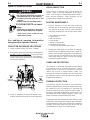
1.b. Operate engines in open, well-ventilated
areas or vent the engine exhaust fumes
outdoors.
____________________________________________________
1.c. Do not add the fuel near an open flame
welding arc or when the engine is running.
Stop the engine and allow it to cool before
refueling to prevent spilled fuel from vaporiz-
ing on contact with hot engine parts and
igniting. Do not spill fuel when filling tank. If
fuel is spilled, wipe it up and do not start
engine until fumes have been eliminated.
____________________________________________________
1.d. Keep all equipment safety guards, covers and devices in
position and in good repair.Keep hands, hair, clothing and
tools away from V-belts, gears, fans and all other moving
parts when starting, operating or repairing equipment.
____________________________________________________
1.e. In some cases it may be necessary to remove safety
guards to perform required maintenance. Remove
guards only when necessary and replace them when the
maintenance requiring their removal is complete.
Always use the greatest care when working near moving
parts.
___________________________________________________
1.f. Do not put your hands near the engine fan.
Do not attempt to override the governor or
idler by pushing on the throttle control rods
while the engine is running.
___________________________________________________
1.g. To prevent accidentally starting gasoline engines while
turning the engine or welding generator during maintenance
work, disconnect the spark plug wires, distributor cap or
magneto wire as appropriate.
i
SAFETY
i
ARC WELDING CAN BE HAZARDOUS. PROTECT YOURSELF AND OTHERS FROM POSSIBLE SERIOUS INJURY OR DEATH.
KEEP CHILDREN AWAY. PACEMAKER WEARERS SHOULD CONSULT WITH THEIR DOCTOR BEFORE OPERATING.
Read and understand the following safety highlights. For additional safety information, it is strongly recommended that you
purchase a copy of “Safety in Welding & Cutting - ANSI Standard Z49.1” from the American Welding Society, P.O. Box
351040, Miami, Florida 33135 or CSA Standard W117.2-1974. A Free copy of “Arc Welding Safety” booklet E205 is available
from the Lincoln Electric Company, 22801 St. Clair Avenue, Cleveland, Ohio 44117-1199.
BE SURE THAT ALL INSTALLATION, OPERATION, MAINTENANCE AND REPAIR PROCEDURES ARE
PERFORMED ONLY BY QUALIFIED INDIVIDUALS.
WARNING
Mar ‘95
ELECTRIC AND
MAGNETIC FIELDS
may be dangerous
2.a. Electric current flowing through any conductor causes
localized Electric and Magnetic Fields (EMF). Welding
current creates EMF fields around welding cables and
welding machines
2.b. EMF fields may interfere with some pacemakers, and
welders having a pacemaker should consult their physician
before welding.
2.c. Exposure to EMF fields in welding may have other health
effects which are now not known.
2.d. All welders should use the following procedures in order to
minimize exposure to EMF fields from the welding circuit:
2.d.1.
Route the electrode and work cables together - Secure
them with tape when possible.
2.d.2. Never coil the electrode lead around your body.
2.d.3. Do not place your body between the electrode and
work cables. If the electrode cable is on your right
side, the work cable should also be on your right side.
2.d.4. Connect the work cable to the workpiece as close as
possible to the area being welded.
2.d.5. Do not work next to welding power source.
1.h. To avoid scalding, do not remove the
radiator pressure cap when the engine is
hot.
CALIFORNIA PROPOSITION 65 WARNINGS
Diesel engine exhaust and some of its constituents
are known to the State of California to cause can-
cer, birth defects, and other reproductive harm.
The engine exhaust from this product contains
chemicals known to the State of California to cause
cancer, birth defects, or other reproductive harm.
The Above For Diesel Engines
The Above For Gasoline Engines

ii
SAFETY
ii
ARC RAYS can burn.
4.a. Use a shield with the proper filter and cover
plates to protect your eyes from sparks and
the rays of the arc when welding or observing
open arc welding. Headshield and filter lens
should conform to ANSI Z87. I standards.
4.b. Use suitable clothing made from durable flame-resistant
material to protect your skin and that of your helpers from
the arc rays.
4.c. Protect other nearby personnel with suitable, non-flammable
screening and/or warn them not to watch the arc nor expose
themselves to the arc rays or to hot spatter or metal.
ELECTRIC SHOCK can
kill.
3.a. The electrode and work (or ground) circuits
are electrically “hot” when the welder is on.
Do not touch these “hot” parts with your bare
skin or wet clothing. Wear dry, hole-free
gloves to insulate hands.
3.b. Insulate yourself from work and ground using dry insulation.
Make certain the insulation is large enough to cover your full
area of physical contact with work and ground.
In addition to the normal safety precautions, if welding
must be performed under electrically hazardous
conditions (in damp locations or while wearing wet
clothing; on metal structures such as floors, gratings or
scaffolds; when in cramped positions such as sitting,
kneeling or lying, if there is a high risk of unavoidable or
accidental contact with the workpiece or ground) use
the following equipment:
• Semiautomatic DC Constant Voltage (Wire) Welder.
• DC Manual (Stick) Welder.
• AC Welder with Reduced Voltage Control.
3.c. In semiautomatic or automatic wire welding, the electrode,
electrode reel, welding head, nozzle or semiautomatic
welding gun are also electrically “hot”.
3.d. Always be sure the work cable makes a good electrical
connection with the metal being welded. The connection
should be as close as possible to the area being welded.
3.e. Ground the work or metal to be welded to a good electrical
(earth) ground.
3.f.
Maintain the electrode holder, work clamp, welding cable and
welding machine in good, safe operating condition. Replace
damaged insulation.
3.g. Never dip the electrode in water for cooling.
3.h. Never simultaneously touch electrically “hot” parts of
electrode holders connected to two welders because voltage
between the two can be the total of the open circuit voltage
of both welders.
3.i. When working above floor level, use a safety belt to protect
yourself from a fall should you get a shock.
3.j. Also see Items 6.c. and 8.
FUMES AND GASES
can be dangerous.
5.a. Welding may produce fumes and gases
hazardous to health. Avoid breathing these
fumes and gases.When welding, keep
your head out of the fume. Use enough
ventilation and/or exhaust at the arc to keep
fumes and gases away from the breathing zone. When
welding with electrodes which require special
ventilation such as stainless or hard facing (see
instructions on container or MSDS) or on lead or
cadmium plated steel and other metals or coatings
which produce highly toxic fumes, keep exposure as
low as possible and below Threshold Limit Values (TLV)
using local exhaust or mechanical ventilation. In
confined spaces or in some circumstances, outdoors, a
respirator may be required. Additional precautions are
also required when welding on galvanized steel.
5.b.
Do not weld in locations near chlorinated hydrocarbon
vapors
coming from degreasing, cleaning or spraying operations.
The heat and rays of the arc can react with solvent vapors
to
form phosgene, a highly toxic gas, and other irritating
products.
5.c. Shielding gases used for arc welding can displace air and
cause injury or death. Always use enough ventilation,
especially in confined areas, to insure breathing air is safe.
5.d. Read and understand the manufacturer’s instructions for this
equipment and the consumables to be used, including the
material safety data sheet (MSDS) and follow your
employer’s safety practices. MSDS forms are available from
your welding distributor or from the manufacturer.
5.e. Also see item 1.b.
Mar ‘95

FOR ELECTRICALLY
powered equipment.
8.a. Turn off input power using the disconnect
switch at the fuse box before working on
the equipment.
8.b. Install equipment in accordance with the U.S. National
Electrical Code, all local codes and the manufacturer’s
recommendations.
8.c. Ground the equipment in accordance with the U.S. National
Electrical Code and the manufacturer’s recommendations.
CYLINDER may explode
if damaged.
7.a. Use only compressed gas cylinders
containing the correct shielding gas for the
process used and properly operating
regulators designed for the gas and
pressure used. All hoses, fittings, etc. should be suitable for
the application and maintained in good condition.
7.b. Always keep cylinders in an upright position securely
chained to an undercarriage or fixed support.
7.c. Cylinders should be located:
• Away from areas where they may be struck or subjected to
physical damage.
• A safe distance from arc welding or cutting operations and
any other source of heat, sparks, or flame.
7.d. Never allow the electrode, electrode holder or any other
electrically “hot” parts to touch a cylinder.
7.e. Keep your head and face away from the cylinder valve outlet
when opening the cylinder valve.
7.f. Valve protection caps should always be in place and hand
tight except when the cylinder is in use or connected for
use.
7.g. Read and follow the instructions on compressed gas
cylinders, associated equipment, and CGA publication P-l,
“Precautions for Safe Handling of Compressed Gases in
Cylinders,” available from the Compressed Gas Association
1235 Jefferson Davis Highway, Arlington, VA 22202.
iii
SAFETY
iii
Mar ‘95
WELDING SPARKS can
cause fire or explosion.
6.a.
Remove fire hazards from the welding area.
If this is not possible, cover them to prevent
the welding sparks from starting a fire.
Remember that welding sparks and hot
materials from welding can easily go through small cracks
and openings to adjacent areas. Avoid welding near
hydraulic lines. Have a fire extinguisher readily available.
6.b. Where compressed gases are to be used at the job site,
special precautions should be used to prevent hazardous
situations. Refer to “Safety in Welding and Cutting” (ANSI
Standard Z49.1) and the operating information for the
equipment being used.
6.c. When not welding, make certain no part of the electrode
circuit is touching the work or ground. Accidental contact
can cause overheating and create a fire hazard.
6.d. Do not heat, cut or weld tanks, drums or containers until the
proper steps have been taken to insure that such procedures
will not cause flammable or toxic vapors from substances
inside. They can cause an explosion even
though
they have
been “cleaned”. For information, purchase “Recommended
Safe Practices for the
Preparation
for Welding and Cutting of
Containers and Piping That Have Held Hazardous
Substances”, AWS F4.1 from the American Welding Society
(see address above).
6.e. Vent hollow castings or containers before heating, cutting or
welding. They may explode.
6.f.
Sparks and spatter are thrown from the welding arc. Wear oil
free protective garments such as leather gloves, heavy shirt,
cuffless trousers, high shoes and a cap over your hair. Wear
ear plugs when welding out of position or in confined places.
Always wear safety glasses with side shields when in a
welding area.
6.g. Connect the work cable to the work as close to the welding
area as practical. Work cables connected to the building
framework or other locations away from the welding area
increase the possibility of the welding current passing
through lifting chains, crane cables or other alternate cir-
cuits. This can create fire hazards or overheat lifting chains
or cables until they fail.
6.h. Also see item 1.c.

iv
SAFETY
iv
Mar. ‘93
PRÉCAUTIONS DE SÛRETÉ
Pour votre propre protection lire et observer toutes les instructions
et les précautions de sûreté specifiques qui parraissent dans ce
manuel aussi bien que les précautions de sûreté générales suiv-
antes:
Sûreté Pour Soudage A L’Arc
1. Protegez-vous contre la secousse électrique:
a. Les circuits à l’électrode et à la piéce sont sous tension
quand la machine à souder est en marche. Eviter toujours
tout contact entre les parties sous tension et la peau nue
ou les vétements mouillés. Porter des gants secs et sans
trous pour isoler les mains.
b. Faire trés attention de bien s’isoler de la masse quand on
soude dans des endroits humides, ou sur un plancher
metallique ou des grilles metalliques, principalement dans
les positions assis ou couché pour lesquelles une grande
partie du corps peut être en contact avec la masse.
c. Maintenir le porte-électrode, la pince de masse, le câble
de soudage et la machine à souder en bon et sûr état
defonctionnement.
d.Ne jamais plonger le porte-électrode dans l’eau pour le
refroidir.
e. Ne jamais toucher simultanément les parties sous tension
des porte-électrodes connectés à deux machines à souder
parce que la tension entre les deux pinces peut être le
total de la tension à vide des deux machines.
f. Si on utilise la machine à souder comme une source de
courant pour soudage semi-automatique, ces precautions
pour le porte-électrode s’applicuent aussi au pistolet de
soudage.
2. Dans le cas de travail au dessus du niveau du sol, se protéger
contre les chutes dans le cas ou on recoit un choc. Ne jamais
enrouler le câble-électrode autour de n’importe quelle partie
du corps.
3. Un coup d’arc peut être plus sévère qu’un coup de soliel,
donc:
a. Utiliser un bon masque avec un verre filtrant approprié
ainsi qu’un verre blanc afin de se protéger les yeux du ray-
onnement de l’arc et des projections quand on soude ou
quand on regarde l’arc.
b. Porter des vêtements convenables afin de protéger la
peau de soudeur et des aides contre le rayonnement de
l‘arc.
c. Protéger l’autre personnel travaillant à proximité au
soudage à l’aide d’écrans appropriés et non-inflammables.
4. Des gouttes de laitier en fusion sont émises de l’arc de
soudage. Se protéger avec des vêtements de protection libres
de l’huile, tels que les gants en cuir, chemise épaisse, pan-
talons sans revers, et chaussures montantes.
5. Toujours porter des lunettes de sécurité dans la zone de
soudage. Utiliser des lunettes avec écrans lateraux dans les
zones où l’on pique le laitier.
6. Eloigner les matériaux inflammables ou les recouvrir afin de
prévenir tout risque d’incendie dû aux étincelles.
7. Quand on ne soude pas, poser la pince à une endroit isolé de
la masse. Un court-circuit accidental peut provoquer un
échauffement et un risque d’incendie.
8. S’assurer que la masse est connectée le plus prés possible
de la zone de travail qu’il est pratique de le faire. Si on place
la masse sur la charpente de la construction ou d’autres
endroits éloignés de la zone de travail, on augmente le risque
de voir passer le courant de soudage par les chaines de lev-
age, câbles de grue, ou autres circuits. Cela peut provoquer
des risques d’incendie ou d’echauffement des chaines et des
câbles jusqu’à ce qu’ils se rompent.
9. Assurer une ventilation suffisante dans la zone de soudage.
Ceci est particuliérement important pour le soudage de tôles
galvanisées plombées, ou cadmiées ou tout autre métal qui
produit des fumeés toxiques.
10. Ne pas souder en présence de vapeurs de chlore provenant
d’opérations de dégraissage, nettoyage ou pistolage. La
chaleur ou les rayons de l’arc peuvent réagir avec les vapeurs
du solvant pour produire du phosgéne (gas fortement toxique)
ou autres produits irritants.
11. Pour obtenir de plus amples renseignements sur la sûreté,
voir le code “Code for safety in welding and cutting” CSA
Standard W 117.2-1974.
PRÉCAUTIONS DE SÛRETÉ POUR
LES MACHINES À SOUDER À
TRANSFORMATEUR ET À
REDRESSEUR
1. Relier à la terre le chassis du poste conformement au code de
l’électricité et aux recommendations du fabricant. Le dispositif
de montage ou la piece à souder doit être branché à une
bonne mise à la terre.
2. Autant que possible, I’installation et l’entretien du poste seront
effectués par un électricien qualifié.
3. Avant de faires des travaux à l’interieur de poste, la debranch-
er à l’interrupteur à la boite de fusibles.
4. Garder tous les couvercles et dispositifs de sûreté à leur
place.

v
SAFETY
v

vi
SAFETY
vi

viivii
Thank You
for selecting a QUALITY product by Lincoln Electric. We want you
to take pride in operating this Lincoln Electric Company product
••• as much pride as we have in bringing this product to you!
Read this Operators Manual completely before attempting to use this equipment. Save this manual and keep it
handy for quick reference. Pay particular attention to the safety instructions we have provided for your protection.
The level of seriousness to be applied to each is explained below:
WARNING
This statement appears where the information must be followed exactly to avoid serious personal injury or
loss of life.
This statement appears where the information must be followed to avoid minor personal injury or damage to
this equipment.
CAUTION
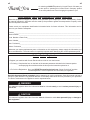
Please Examine Carton and Equipment For Damage Immediately
When this equipment is shipped, title passes to the purchaser upon receipt by the carrier. Consequently, Claims
for material damaged in shipment must be made by the purchaser against the transportation company at the
time the shipment is received.
Please record your equipment identification information below for future reference. This information can be
found on your machine nameplate.
Product _________________________________________________________________________________
Model Number ___________________________________________________________________________
Code Number or Date Code_________________________________________________________________
Serial Number____________________________________________________________________________
Date Purchased___________________________________________________________________________
Where Purchased_________________________________________________________________________
Whenever you request replacement parts or information on this equipment, always supply the information you
have recorded above. The code number is especially important when identifying the correct replacement parts.
On-Line Product Registration
- Register your machine with Lincoln Electric either via fax or over the Internet.
• For faxing: Complete the form on the back of the warranty statement included in the literature packet
accompanying this machine and fax the form per the instructions printed on it.
• For On-Line Registration: Go to our
WEB SITE at www.lincolnelectric.com. Choose “Quick Links” and then
“Product Registration”. Please complete the form and submit your registration.

viii viii
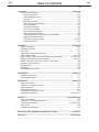
TABLE OF CONTENTS
Page
Installation .......................................................................................................Section A
Technical Specifications ........................................................................................A-1
Safety Precautions ..........................................................................................A-2
Select Suitable Location..................................................................................A-2
Stacking ..........................................................................................................A-2
Machine Grounding.........................................................................................A-2
High Frequency Connections..........................................................................A-2
Input Connections ...........................................................................................A-2
Connection Diagram .......................................................................................A-3
Input Fuse and Supply ....................................................................................A-3
Input Voltage Change Over ............................................................................A-3
Electrode and Work Cable ..............................................................................A-3
Cable Inductance and Its Effects on Pulse Welding .......................................A-4
Negative Electrode Polarity.............................................................................A-4
Connection of Wire Feeders....................................................................A-5, A-6
Parallel Operations..........................................................................................A-6
________________________________________________________________________
Operation .........................................................................................................Section B
Safety Precautions ................................................................................................B-1
General Description ..............................................................................................B-1
Duty Cycle .............................................................................................................B-1
Operational Features and Controls........................................................................B-1
Upper Control Panel.......................................................................................B-1, B-2
Hidden Middle Control Panel and Advance Process Panel.....................B-2 thru B-5
Weld Mode Details and Pulse Programs .......................................................B-6, B-7
Middle and Lower Case Panel Controls, Connections ..........................................B-8
Remote Control Selection......................................................................................B-8
Auxiliary Power......................................................................................................B-9
Limitations..............................................................................................................B-9
Recommended Processes ....................................................................................B-9
_______________________________________________________________________
Accessories.....................................................................................................Section C
Options / Accessories............................................................................................C-1
Field Installed Options...........................................................................................C-1
________________________________________________________________________
Maintenance ....................................................................................................Section D
Safety Precautions ................................................................................................D-1
Capacitor Discharge Procedure ............................................................................D-1
Visual Inspection ...................................................................................................D-1
Routine Maintenance.............................................................................................D-1
Overload and Thermal Protection..........................................................................D-1
Calibration Procedures............................................................................D-2 thru D-4
________________________________________________________________________
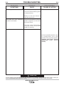
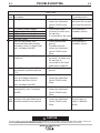
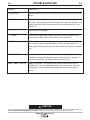
Section E ..............................................................................................Troubleshooting
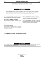
Safety Precautions.................................................................................................E-1
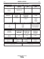
How to Use Troubleshooting Guide.......................................................................E-1
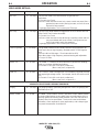
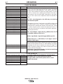
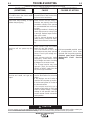
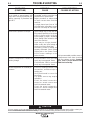
Troubleshooting Guide ...........................................................................E-2 Thru E-4
Fault Codes ...........................................................................................................E-5
Displays and Description .......................................................................................E-6
________________________________________________________________________
Connection, Wiring Diagrams and Dimension Prints ..................................Section F
________________________________________________________________________
Parts List ......................................................................................................P525 Series
________________________________________________________________________

INVERTEC V450-PRO (CE)
A-1
INSTALLATION
A-1
TECHNICAL SPECIFICATIONS -
INVERTEC V450-PRO (CE)
OUTPUT
RECOMMENDED INPUT WIRE AND FUSE SIZES
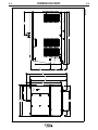
PHYSICAL DIMENSIONS
TEMPERATURE RANGES
INPUT AT RATED OUTPUT - THREE PHASE ONLY
INPUT VOLTS
380-415V
50/60HZ.
INPUT
VOLTAGE /
FREQUENCY
380-415
50/60 Hz
HEIGHT
26.10 in
663 mm
WIDTH
19.86 in
505 mm
DEPTH
32.88 in
835 mm
WEIGHT
278 lbs.
126 kg.
TYPE 75°C
(SUPER LAG)
OR BREAKER
SIZE (AMPS)
63 AMP
TYPE 75°C
GROUND WIRE IN
CONDUIT AWG
(MM
2
) SIZES
10 (6)
TYPE 75°C
COPPER WIRE IN
CONDUIT AWG
(MM
2
) SIZES
8 (10)
PULSE
VOLTAGE
RANGE
5 - 55 VDC
AUXILIARY
POWER
220 VAC AT
5 AMPS
24VAC
42VAC at
10 AMPS
PULSE AND
BACKGROUND
TIME RANGE
100 MICRO SEC. -
3.3 SEC.
PULSE
FREQUENCY
0.15 - 1000 Hz
INPUT
CURRENT
I
1
max
48
INPUT
CURRENT
I
1
eff
37
OUTPUT
CONDITIONS
400A@36V 100%
500A@40V 60%
OPERATING TEMPERATURE RANGE
-20°C to +40°C
STORAGE TEMPERATURE RANGE
-40°C to +40°C
MIG/MAG
FCAW
SMAW
GTAW
Pulse
50-500 Average Amps
40-500 Average Amps
55-500 Average Amps
5-500 Average Amps
5-750 Peak Amps
30-76
76
76
18-76
76
OPEN CIRCUIT VOLTAGE PROCESS CURRENT RANGE (DC) CURRENT

A-2
INSTALLATION
A-2
INVERTEC V450-PRO (CE)
LIFTING
Lift the machine by the lift bail only. The lift bail is
designed to lift the power source only. Do not attempt
to lift the V450-PRO (CE) with accessories attached to
it.
STACKING
V450-PRO (CE) machines can be stacked to a maxi-
mum of 3 high.
The bottom machine must always be placed on a
firm, secure, level surface. There is a danger of
machines toppling over if this precaution is not
taken.
-------------------------------------------------------------
MACHINE GROUNDING
The frame of the welder must be grounded. A ground
terminal marked with the symbol is located inside
the reconnect/input access door for this purpose. See
your local and national electrical codes for proper
grounding methods.
HIGH FREQUENCY PROTECTION
Locate the V450-PRO (CE) away from radio con-
trolled machinery.
The normal operation of the V450-PRO (CE) may
adversely affect the operation of RF controlled
equipment, which may result in bodily injury or
damage to the equipment.
INPUT CONNECTION
Only a qualified electrician should connect the
input leads to the V450-PRO (CE). Connections
should be made in accordance with all local and
national electrical codes and the connection dia-
gram located on the inside of the reconnect/input
access door of the machine. Failure to do so may
result in bodily injury or death.
-------------------------------------------------------------
Use a three-phase supply line. A 1.75 inch (45 mm)
diameter access hole for the input supply is located on
the upper left case back next to the input access door.
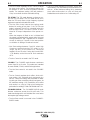
Connect L1, L2, L3 and ground according to the Input
Supply Connection Diagram decal located on the
inside of the input access door or refer to Figure A.1
on the following page.
SAFETY PRECAUTIONS
Read this entire installation section before you start
installation.
ELECTRIC SHOCK can kill.
• Only qualified personnel should
perform this installation.
• Turn the input power OFF at the
disconnect switch or fuse box
before working on this equipment.
Turn off the input power to any other equipment con-
nected to the welding system at the disconnect
switch or fuse box before working on the equipment.
• Do not touch electrically hot parts.
• Always connect the V450-PRO (CE) grounding lug
(located inside the reconnect input access door) to
a proper safety (Earth) ground.
----------------------------------------------------------
SELECT SUITABLE LOCATION
Do not use the Invertec in outdoor environments without
appropriate protection. The V450-PRO (CE) power
source should not be subjected to falling water, nor
should any parts of it be submerged in water. Doing so
may cause improper operation as well as pose a safety
hazard. The best practice is to keep the machine in a dry,
sheltered area.
Do not mount the V450-PRO (CE) over combustible
surfaces. Where there is a combustible surface
directly under stationary or fixed electrical equip-
ment, that surface shall be covered with a steel plate
at least .060" (1.6mm) thick, which shall extend not
less than 5.90" (150mm) beyond the equipment on all
sides.
-------------------------------------------------------------
Place the welder where clean cooling air can freely circu-
late in through the rear louvers and out through the case
sides and bottom. Water, Dirt, dust, or any foreign materi-
al that can be drawn into the welder should be kept at a
minimum. Failure to observe these precautions can result
in excessive operating temperatures and nuisance shut-
downs.
Machines are equipped with F.A.N. (fan as needed) cir-
cuitry. The fan runs whenever the output is enabled,
whether under loaded or open circuit conditions. The fan
also runs for a period of time (approximately 5 minutes)
after the output is disabled, to ensure all components are
properly cooled.
If desired, the F.A.N. feature can be disabled (causing the
fan to run whenever the power source is on). To disable
F.A.N., connect leads 444 and X3A together at the output
of the solid state fan control relay, located on the back of
the Control PC board enclosure. (See Wiring Diagram)
WARNING
WARNING
WARNING
CAUTION
CAUTION

A-3
INSTALLATION
INVERTEC V450-PRO (CE)
A-3
INPUT FUSE AND SUPPLY WIRE
CONSIDERATIONS
Refer to the Technical Specifications at the beginning
of this Installation section for recommended fuse and
wire sizes. Fuse the input circuit with the recommend-
ed super lag fuse or delay type breakers (also called
“inverse time” or “thermal/magnetic” circuit breakers).
Choose an input and grounding wire size according to
local or national electrical codes. Using fuses or circuit
breakers smaller than recommended may result in
“nuisance” shut-offs from welder inrush currents, even
if the machine is not being used at high currents.
INPUT VOLTAGE CONNECTION
PROCEDURE
Only a qualified electrician should connect the
input leads to the V450-PRO (CE). Connections
should be made in accordance with all local and
national electrical codes and the connection dia-
gram located on the inside of the reconnect/input
access door of the machine. Failure to do so may
result in bodily injury or death.
------------------------------------------------------------------------
Use a three-phase supply line. A 1.75 inch (45 mm)
diameter access hole for the input supply is located on
the case back. Connect L1, L2, L3 and ground accord-
ing to the Input Supply Connection Diagram decal
located on the inside of the input access door.
NOTE: Turn main input power to the machine OFF before performing connection procedure. Failure to
do so will result in damage to the machine.
FIGURE A.1 - CONNECTION DIAGRAM ON CONNECTION/INPUT ACCESS DOOR
W / L3
V / L2
U / L1
THE LINCOLN ELECTRIC CO. CLEVELAND, OHIO U.S.A.
XA
S24190
use or service this equipment.
Do not touch electrically live parts.
removed.
Only qualified persons should install,
Do not operate with covers
inspecting or servicing machine.
Disconnect input power before
.
.
.
.
CR1
INPUT SUPPLY CONNECTION DIAGRAM
ELECTRODE AND WORK CABLE
CONNECTIONS
Connect a work lead of sufficient size and length (Per
Table 1) between the proper output terminal on the
power source and the work. Be sure the connection to
the work makes tight metal-to-metal electrical contact.
To avoid interference problems with other equipment
and to achieve the best possible operation, route all
cables directly to the work and wire feeder. Avoid
excessive lengths and do not coil excess cable.
Minimum work and electrode cable sizes are as follows:
TABLE A.1
(Current (60% Duty Cycle)
MINIMUM COPPER
WORK CABLE SIZE AWG
Up To-100 Ft. Length (30 m)
400 Amps 2/0 (67 mm
2
)
500 Amps 3/0 (85 mm
2
)
600 Amps 3/0 (85 mm
2
)
NOTE: K1796 coaxial welding cable is recommended
to reduce the cable inductance in long cable lengths.
This is especially important when Pulse welding up to
350 amps.
When using inverter type power sources like the
V450-PRO (CE), use the largest welding (electrode
and work) cables that are practical. At least 2/0 (67
mm
2
) copper wire - even if the average output cur-
rent would not normally require it. When pulsing,
the pulse current can reach very high levels.
Voltage drops can become excessive, leading to
poor welding characteristics, if undersized weld-
ing cables are used.
------------------------------------------------------------------------
CAUTION
WARNING

A-4
INSTALLATION
INVERTEC V450-PRO (CE)
A-4
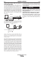
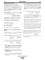
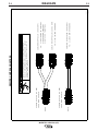
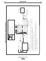
CABLE INDUCTANCE, AND ITS EFFECTS
ON PULSE WELDING
For Pulse Welding processes, cable inductance will
cause the welding performance to degrade. For the
total welding loop length less than
50 ft.(15.24m), tradi-
tional welding cables may be used without any effects
on welding performance. For the total welding loop
length greater than
50 ft.(15.24m)), the K1796 Coaxial
Welding Cables are recommended. The welding loop
length is defined as the total of electrode cable length
(A) + work cable length (B) + work length (C) (See
Figure A.2).
For long work piece lengths, a sliding ground should
be considered to keep the total welding loop length
less than
50 ft.(15.24m). (See Figure A.3.)
Output connections on some V450-PRO (CE) are
made via 1/2-13 threaded output studs located
beneath the spring loaded output cover at the bottom
of the case front.
Most welding applications run with the electrode being
positive (+). For those applications, connect the elec-
trode cable between the wire feeder and the positive
(+) output stud on the power source (located beneath
the spring loaded output cover near the bottom of the
case front). Connect the other end of the electrode
cable to the wire drive feed plate. The electrode cable
lug must be against the feed plate. Be sure the con-
nection to the feed plate makes tight metal-to-metal
electrical contact. The electrode cable should be sized
according to the specifications given in the work cable
connections section. Connect a work lead from the
negative (-) power source output stud to the work
piece. The work piece connection must be firm and
secure, especially if pulse welding is planned.
For additional Safety information regarding the elec-
trode and work cable set-up, See the standard "SAFE-
TY INFORMATION" located in the front of the
Instruction Manuals.
Excessive voltage drops caused by poor work
piece connections often result in unsatisfactory
welding performance.
------------------------------------------------------------------------
NEGATIVE ELECTRODE POLARITY
When negative electrode polarity is required, such as
in some Innershield applications, switch the output
connections at the power source (electrode cable to
the negative (-) stud, and work cable to the positive (+)
stud).
CAUTION
B
A
C
FIGURE A.2
WORK
V450-PRO
A
C
B
FIGURE A.3
K1796 COAXIAL CABLE
MEASURE FROM END
OF OUTER JACKET OF
CABLE
C
A
B
WORK
SLIDING
WORK
V450-PRO

A-5
INSTALLATION
INVERTEC V450-PRO (CE)
A-5
CONNECTIONS OF WIRE FEEDERS TO V450-PRO (CE)
LF-72, 74 Connection Instructions
• Turn the Invertec power switch "off".
• Connect the K1797-[ ] control cable from the LF-72, 74
to the 14-pin MS-style connector.
• Connect the electrode cable to the output terminal of
the polarity required by electrode. Connect the work
lead to the other terminal.
• If a remote control such as K857 is to be used with the
LF-72, 74 the remote can be connected directly to the
6-pin MS-style connector on the front of the Invertec or
use a K864 adapter to connect the LF-72, 74 and the
remote to the 14-pin MS-style connector.
LN-10, DH-10 Connection Instructions
• Turn the Invertec power switch "off"
• Connect the K1505 control cable from the LN-10 to the
14-pin MS-style connector.
• Connect the electrode cable to the output terminal of
polarity required by the electrode. Connect the work
lead to the other terminal.
• Set the meter polarity switch on the front of the Invertec
to coincide with wire feeder polarity used.
• See the LN-10 manual for details on accessing Control
DIP Switch. Dip Switches for the V350 and the same
settings may be used for the V450.
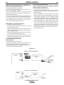
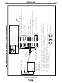
LN-15 Connection Instructions
(See Figure A.4)
• Turn the Invertec power switch "off".
• Connect the electrode cable to the output terminal of
polarity required by electrode. (See Figures below)
• Set the meter polarity switch on the front of the Invertec to
coincide with wire feeder polarity used.
LN-25 Connection Instructions
-Not recommended for Pulse Welding with the
Advanced Process Panel Kit).
• Turn the Invertec power switch "off".
• Connect the electrode cable to the output terminal of
polarity required by electrode. Connect the work lead to
the other terminal.
• LN-25 with Remote Control 6-Pin (K444-1) and 14-pin
(K444-2) remotes can be connected directly to the 6-pin &
14-pin MS-style connectors. The 42 Volt Remote Voltage
and Output Control (K624-1) Kit can be connected to the
V450’s 14-pin MS-style connector using Remote Control
Cable assembly K627- [ ]. LN-25s with a K431-1 remote
kit can be connected to the V450’s 14-pin MS-style con-
nector using a K432 cable and K876 adapter. (See con-
nection diagram S19899). Or the K432 cable could be
modified with a K867 Universal Adapter Plug (See con-
nection diagram S19405) to connect it to the V450’s 14-
pin MS-style connector.
CONTROL CABLE MODEL
Electrode Cable
V450-PRO
STUD
14-PIN
Electrode Cable
Work
Clamp
semiautomatic
wire feeder
K1870-1
Output T
erminals
erminals
Always Hot.
Power source contactor
switch must be in the
"ON" position or use a
K848 Junper Plug Kit.
ACROSS THE ARC MODEL
V450-PRO
STUD
FIGURE A.4

A-6
INSTALLATION
INVERTEC V450-PRO (CE)
A-6
LN-742 Connection Instructions
• Turn the Invertec power switch "off"
• Either a K1819-1 Input cable assembly is required
to connect the LN-742 to the Invertec.
• Connect the control cable from the LN-742 to the
14-pin MS-style connector.
• Connect the electrode cable to the output terminal
of the polarity required by electrode. Connect the
work lead to the other terminal.
• Set the meter polarity switch on the front of the
Invertec to coincide with wire feeder polarity used.
The wire feeder will now display the welding volt-
age.
• If a remote control such as K857 is to be used with the
LN-742, the remote can be connected directly to the 6-
pin MS-style connector on the front of the Invertec or use
a K864 adapter to connect the LN-742 and the remote to
the 14-pin MS-style connector.
Cobramatic Connection Instructions
• Turn the Invertec power switch "off"
• Connect the control cable from the Cobramatic to
the 14-pin MS-style connector.
• Connect the electrode cable to the output terminal
of the polarity required by electrode. Connect the
work lead to the other terminal.
• Set the meter polarity switch on the front of the
Invertec to coincide with wire feeder polarity used.
• If a remote control such as K857 is to be used with
the Cobramatic, the remote can be connected
directly to the 6-pin MS-style connector on the front
of the Invertec or use a K864 adapter to connect
the cobramatic and the remote to the 14-pin MS-
style connector.
General Instructions for Connection of Wire
Feeders to V450-Pro
Wire feeders other than those listed above may be
used provided that the auxiliary power supply rating of
the V450-Pro is not exceeded and the V450Pro output
is not actively controlled by the wire feeder. (Like an
LN-9). K867 universal adapter plug is required. See
connection diagram S24985 on page F-4.
REMOTE CONTROL OF INVERTEC
Remote Control K857, Hand Amptrol K963 and Foot
Amptrol K870 may be used.
PARALLEL OPERATION
The V450-Pro are operable in parallel in CC mode.
For best results, the currents of each machine should
be reasonably equally balanced. As an example, with
two machines set up in parallel for a 800 amps proce-
dure, each machine should be set to deliver approxi-
mately 400 amps, not 450 amps from one and 350
amps from the other. This will minimize nuisance shut-
down conditions. In general, more than two machines
in parallel will not be effective due to the voltage
requirements of procedures in that power range.
To set machine outputs, start with output control pots
and arc control pots in identical positions. Use the out-
put control pots to balance the currents and maintain
the desired current. The arc control pots should be
kept identical on the two machines.

B-1
OPERATION
INVERTEC V450-PRO (CE)
B-1
SAFETY PRECAUTIONS
ELECTRIC SHOCK can kill.
• Do not touch electrically live parts or
electrode with skin or wet clothing.
• Insulate yourself from work and
ground.
• Always wear dry insulating gloves.
------------------------------------------------------------------------
FUMES AND GASES can be danger-
ous.
• Keep your head out of fumes.
• Use ventilation or exhaust to remove
fumes from breathing zone.
------------------------------------------------------------------------
WELDING SPARKS can cause fire or
explosion.
• Keep flammable material away.
• Do not weld on closed containers.
------------------------------------------------------------------------
ARC RAYS can burn eyes and skin.
• Wear eye, ear and body
protection.
------------------------------------------------------------
See additional warning information at
front of this operator’s manual.
-----------------------------------------------------------
WARNING
GENERAL DESCRIPTION
The Invertec V450-PRO (CE) offers multi-process CV,
CC, and DC welding and is rated 570 amps, 43 volts
at a 60% duty cycle.
DUTY CYCLE
The V450-PRO (CE) is rated at 570 amps, 60% duty
cycle (based on a 10 minute cycle). It is also rated at
450 amps, 100% duty cycle.
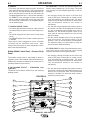
OPERATIONAL FEATURES and CONTROLS:
UPPER CONTROL PANEL
1. ON, OFF- SWITCH
2. AMPS Meter
• Prior to STICK or TIG operation (current flow), the
meter displays preset current value (either +/- 2
amps or +/- 3% (e.g. 3 amps on 100), whichever is
greater).
• Prior to CV operation, the meter displays four dash-
es indicating non-presettable AMPS.
• During welding, this meter displays actual average
amps.
• After welding, the meter holds the actual current
value for 5 seconds. Output adjustment while in the
"hold" period results in the "prior to operation" char-
acteristics stated above. The displays blink indicat-
ing that the machine is in the "Hold" period.
3. VOLT METER
• Prior to CV operation (current flow), the meter dis-
plays desired preset voltage value (+/- .5V).
• Prior to STICK or TIG operation, the meter displays
the Open Circuit Voltage of the Power Source or
four dashes if the output has not been turned on.
• During welding, this meter displays actual average
volts.
• After welding, the meter holds the actual voltage
value for 5 seconds. The displays blink indicating
that the machine is in the "Hold" period.
• Output adjustment while in the "hold" period results
in the "prior to operation" characteristics stated
above.
4. OUTPUT CONTROL
• Output control is conducted via a single turn poten-
tiometer.
• Adjustment is indicated by the meters as stated
above.
• When in TIG modes, this control sets the maximum
welding current. Full depression of a foot or hand
Amptrol results in the preset level of current.
5. WELD TERMINALS-REMOTE / ON
• Two status lights indicate the location of trigger con-
trol as determined by the "WELD TERMINALS"
push button.
• If trigger control is local "weld terminals on", the ON
display will be lit.
• If trigger control is remote "weld terminals remotely
controlled", the REMOTE display will be lit.
• The unit will power up in "pre-determined preferred"
trigger modes.
STICK = ON
CV = REMOTE
TIG = REMOTE if remote output controls are
attached to the machine.
TIG = 0N if remote output controls are not attached to
the machine.
For all versions, these trigger modes can be over-ridden
(switched) with the WELD TERMINALS push button. When
changed, the unit will power up in the configuration it was in
when it was last powered down.

B-2
OPERATION
B-2
6.
THERMAL
• This status light indicates when the power source has
been driven into thermal overload. If the output terminals
were "ON", the "ON" light will blink indicating that the out-
put will be turned back on once the unit cools down to an
acceptable temperature level. If the unit was operating in
the "REMOTE" mode, the trigger will need to be opened
before or after the thermal has cleared and closed after
the machine has cooled down to an acceptable tempera-
ture to establish output.
7.
CONTROL-REMOTE / LOCAL
• Two status lights indicate the location of output control as
pre-determined by the power sources auto-configure sys-
tem.
• The LOCAL display will be lit when control is at the power
source.
• The REMOTE display will be lit when a remote pot/control
is detected.
These Output Control configurations can be overridden
(switched) with the CONTROL push button. When
changed, the unit will power up in the configuration it was in
when it was last powered down.
Hidden Middle Control Panel – Process Set Up
Panel
The middle control panel is removable to allow for
upgrades (see Field Installed Options/Accessories).
Additionally, this panel is hidden by an access door to
provide protection to the controls.
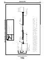
8. WELD MODE SELECT - STANDARD (See
Figure B.1)
The Mode Control button selects from the following
welding modes.
CC-STICK SOFT: The Stick Soft process features con-
tinuous control ranging from 5 to 570 amps. This mode
was intended for most SMAW applications, and Arc
Gouging.
• Arc Gouging: Setting the output of the Stick Soft
mode to 570 amps or setting the arc control to maxi-
mum will enable the arc-gouging mode. The actual
output current will depend on the size of carbon used.
The recommended maximum size carbon is
3/8"(9.5mm).
• The Hot Start control regulates the starting current at
arc initiation. Hot Start can be adjusted from minimum
(0), with no additional current added at arc start, to
maximum (10), with double the preset current or 570
amps (max of machine) added for the first second
after arc initiation.
• The Arc Control regulates the Arc Force to adjust the
short circuit current. The minimum setting (-10) will
produce a "soft" arc and will produce minimal spatter.
The maximum setting (+10) will produce a "crisp" arc
and will minimize electrode sticking.
CC-STICK CRISP:The Stick Crisp mode features contin-
uous control from 5 to 570 amps with a crisp shorting
response optimized for E6010 type electrodes.
• Arc Gouging: Setting the output of the Stick Crisp
mode to 570 amps or setting the arc control to maxi-
mum will enable the arc-gouging mode. The actual
output current will depend on the size of carbon used.
The recommended maximum size carbon is
3/8"(9.5mm).
• The Hot Start control regulates the starting current at
arc initiation. Hot Start can adjust starting current up or
down by 25% of the preset value. The recommended
setting for Hot Start is 5 where the initial current is
equal to the preset current.
IINVERTEC V450-PRO (CE)
OUTPUT
MPSMPS
A
OLOLTSTS
V
REMOTEREMOTE
LOCALLOCAL
CONTROLCONTROL
SELECTSELECT
SOFT
CRIP
HI-FREQ
TIG
TOUCH
START
TIG
2
7
6
3
1
4
5
8
9
13
12
14
15
11
10
FIGURE B.1

B-3
OPERATION
B-3
• The Arc Control regulates the Arc Force to adjust
the short circuit current. The minimum setting (-10)
will produce a "soft" arc and will produce minimal
spatter. The maximum setting (+10) will produce a
"crisp" arc and will minimize electrode sticking.
TIG GTAW: The TIG mode features continuous con-
trol from 5 to 570 amps. The TIG mode can be run in
either the TIG touch start or high frequency (optional
equipment required) assisted start mode.
• The Hot Start control selects the starting mode
desired. A setting of less than 5, the TIG lift start
mode is selected. The OCV is controlled below 10v
and the short circuit "TIG touch" current is main-
tained at 25 amps independent of the preset cur-
rent.
When the tungsten is lifted, an arc is initiated and
the output is regulated at the preset value. Hot start
settings between 0 and 5 regulate the arc initiation
current. A setting of 5 results in the most positive
arc initiation. A setting of 0 reduces hot start.
• Hot Start settings between 5 and 10, select high
frequency assisted starting TIG mode. In this
range, the OCV of the machine is controlled
between 50 and 70 volts. If using the Lincoln K930-
1 TIG Module, set the Hot start to 10 for maximum
OCV.
• The Arc Control is not used in the TIG mode.
CV-WIRE: The CV-WIRE mode features continuous
control from 10 to 40 volts. This mode was intended
for most GMAW, FCAW, and MCAW applications.
• The Hot Start control is not used in the CV-WIRE
mode.
• The Arc Control regulates pinch effect. At the mini-
mum setting (-10), minimizes pinch and results in a
soft arc. Low pinch settings are preferable for weld-
ing with gas mixes containing mostly inert gases. At
the maximum setting (+10), maximizes pinch effect
and results in a crisp arc. High pinch settings are
preferable for welding FCAW and GMAW with CO
2.
CV-INNERSHIELD: The CV-INNERSHIELD mode
features continuous control from 10 to 45 volts. This
mode was designed for self-shielded flux cored wires
that require tight voltage control.
• The Hot Start control is not used in the CV-INNER-
SHIELD mode.
IINVERTEC V450-PRO (CE)
• The Arc Control regulates pinch effect. At the mini-
mum setting (-10), minimizes pinch and results in a
soft arc. At the maximum setting (+10), maximizes
pinch effect and results in a crisp arc. Most self-
shielded wires work well at an Arc Control setting of 5.

B-4
OPERATION
B-4
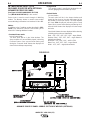
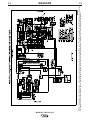
8A. WELD MODE SELECT-FOR
MACHINES EQUIPPED WITH OPTIONAL
ADVANCED PROCESS PANEL
(See Figure B.2 UPPER AND MIDDLE SECTION)
See (WELD MODE DETAILS) in this section.
Select knob is used to scroll through all Welding
modes. The Memory button is used to store and/or
access Welding information into locations M1 thru M8.
Modes:
In addition to the 5 welding modes described in SEC-
TION 7, the Advance Process Panel allows you to
select the Following additional modes.
• Constant Power mode
In the Power Mode;
The work point will be in the Volts window. The
Amp window will have CP displayed indicating
Constant Power. Once current starts flowing and
during the 5 second “Hold” feature the displays will
show Volts and Amps respectively.
IINVERTEC V450-PRO (CE)
• Gouge Mode
The gouging mode is specifically designed for car-
bon arc gouging with electrodes up to 3/8”.
• Pulsed Modes
In Pulse Modes;
The work point will be in the Amps window and
should be set close to the wire feed speed of the
wire feeder in inches per minute. The Volts window
will have SPd displayed indicating Wire Feed
Speed. Once current starts flowing and during the 5
second “Hold” feature the displays will show amps
and volts.
Pulse Mode features that are displayed while selecting
a Welding pulse mode are listed below;
Steel - .030”, .035”, .045”, .052”, 1/16”– Argon Blends
Stainless Steel - .030”, .035”, .045”– Argon Blends &
Helium/Argon Blends
Aluminum - .035”, 3/64”, 1/16”– 4043 & 5356
Metal Core - .045”, .052”, 1/16”– Argon Blends
Nickel - .035”, .045”– Argon/Helium blends
OUTPUT KNOB
REMOTE
REMOTE
ON
ON
REMOTE
REMOTE
LOCAL
LOCAL
WELD
WELD
TERMINALS
TERMINALS
CONTR
CONTR
OL
OL
SELECT
SELECT
SELECT
SELECT
MPS
MPS
A
OL
OL
TS
TS
V
ADVANCE PROCESS PANEL- MIDDLE SECTION OF WELDER (OPTIONAL)
MEMOR
MEMORY
MEMORY BUTTON
(M1 THRU M8)
SELECT BUTTON
(HOT START OR ARC CONTROL)
ADJUST KNOB
(0 THRU +
10 HOT START)
(-10 THRU 0 AND 0 THRU +10 ARC CONTROL)
SELECT KNOB
(SCOLLS WELDING PROC
ESSES)
SELECT
SELECT
ADJUST
ADJUST
SELECT
SELECT
FIGURE B.2

B-5
OPERATION
B-5
IINVERTEC V450-PRO (CE)
MEMORY SELECTIONS:
(See Figure B.2 for location of controls)
The MEMORY button and SELECT knob are used
together to select a welding process and store it in
memory (M1 thru M8). The SELECT knob scrolls
through the, welding process modes and memory M1
thru M8. The MEMORY button stores the welding
process in memory.
• SELECT button (The right button) selects between
the "Hot Start" or "Arc Control". The < will indicate
the active feature shown below.
Right Digital Window
"Hot Start" (-10 to 0 +10)
"Arc Control" (0 to 10) <
• The ADJUST knob adjusts the desired settings for
the Hot Start or Arc Control feature that is active.
WELDING PROCESS MODES AVAILABLE
Stick SMAW, TIG GTAW
Gouge CAG, CV MIG GMAW
CV Flux Core, Pulse MIG
ELECTRODE MATERIAL
Steel, Metal Core, Stainless, Aluminum, Nickel
EXAMPLE OF SAVING WELDING MODES TO
MEMORY
The following example is how to select Pulse MIG
using .035 steel and store it into memory.
1. Turn the Select knob until welding process is dis-
played.
RIGHT WINDOW LEFT WINDOW
Pulse MIG Argon Blends
Steel .035
2. Wait two seconds and the right window will display
Arc Control on the second line on the right side.
Pulse MIG Argon Blends
Steel .035 Arc Cntrl ### <
3. SPd is displayed in the upper right Volts window.
The left Amps window matches the desired wire
feed speed that is set on the wire feeder. Adjust the
Output knob until desired number is displayed.
4. Start welding. If the arc length is too short turn the
Output knob up. If the arc length is too long turn
the Output knob down.
The Arc Control which is displayed in the right digital
window can be used to fine-tune the arc length and
characteristics.
5. After all adjustments have been made press and
hold the Memory button until the display changes.
The right and the left window will display a memory
position, lets say M1(or turn knob to select memory
of your choice. To store in M1 push the Memory
button again to save the Pulse Mig mode to memo-
ry M1.
6. The display in the digital windows read as follows:
M1 Pulse MIG Argon Blends
Steel .035 Arc Cntrl 1.2
7. To save a second welding mode to a memory posi-
tion of your choice, turn the Select knob until the
desired welding process mode is displayed in right
digital window. Then follow steps 2 thru 6.
8. Adjust the output control to the correct wire feed
setting and the V450-PRO (CE) is ready to weld
again. (Note: The wire feed speed setting is not
stored in memory and will need to be reset.)
9. Adjust the Arc Control and note that the M1 goes
away indicating that the V450-PRO (CE) settings
no longer match what is stored in memory. Going
back to the original settings will not bring the M1
back. You will need to push the Memory button to
recall the original settings in M1.
Note: After all memory’s M1 thru M8 are used and the
welder needs to store another welding process, a new
welding process will overwrite what was originally in
the memory and will read,
Save to MEM
M1 Overwrite
M1 which stored Pulse Mig is Overwritten with the
new welding process.
La page est en cours de chargement...
La page est en cours de chargement...
La page est en cours de chargement...
La page est en cours de chargement...
La page est en cours de chargement...
La page est en cours de chargement...
La page est en cours de chargement...
La page est en cours de chargement...
La page est en cours de chargement...
La page est en cours de chargement...
La page est en cours de chargement...
La page est en cours de chargement...
La page est en cours de chargement...
La page est en cours de chargement...
La page est en cours de chargement...
La page est en cours de chargement...
La page est en cours de chargement...
La page est en cours de chargement...
La page est en cours de chargement...
La page est en cours de chargement...
La page est en cours de chargement...
La page est en cours de chargement...
La page est en cours de chargement...
La page est en cours de chargement...
-
 1
1
-
 2
2
-
 3
3
-
 4
4
-
 5
5
-
 6
6
-
 7
7
-
 8
8
-
 9
9
-
 10
10
-
 11
11
-
 12
12
-
 13
13
-
 14
14
-
 15
15
-
 16
16
-
 17
17
-
 18
18
-
 19
19
-
 20
20
-
 21
21
-
 22
22
-
 23
23
-
 24
24
-
 25
25
-
 26
26
-
 27
27
-
 28
28
-
 29
29
-
 30
30
-
 31
31
-
 32
32
-
 33
33
-
 34
34
-
 35
35
-
 36
36
-
 37
37
-
 38
38
-
 39
39
-
 40
40
-
 41
41
-
 42
42
-
 43
43
-
 44
44


Lincoln Electric INVERTEC V450-PRO Mode d'emploi
- Catégorie
- Système de soudage
- Taper
- Mode d'emploi
dans d''autres langues
Documents connexes
-
Lincoln Electric POWER MIG 180 Manuel utilisateur
-
-
-
Lincoln Electric LN-25 Pro Mode d'emploi
-
-
-
-
-
-