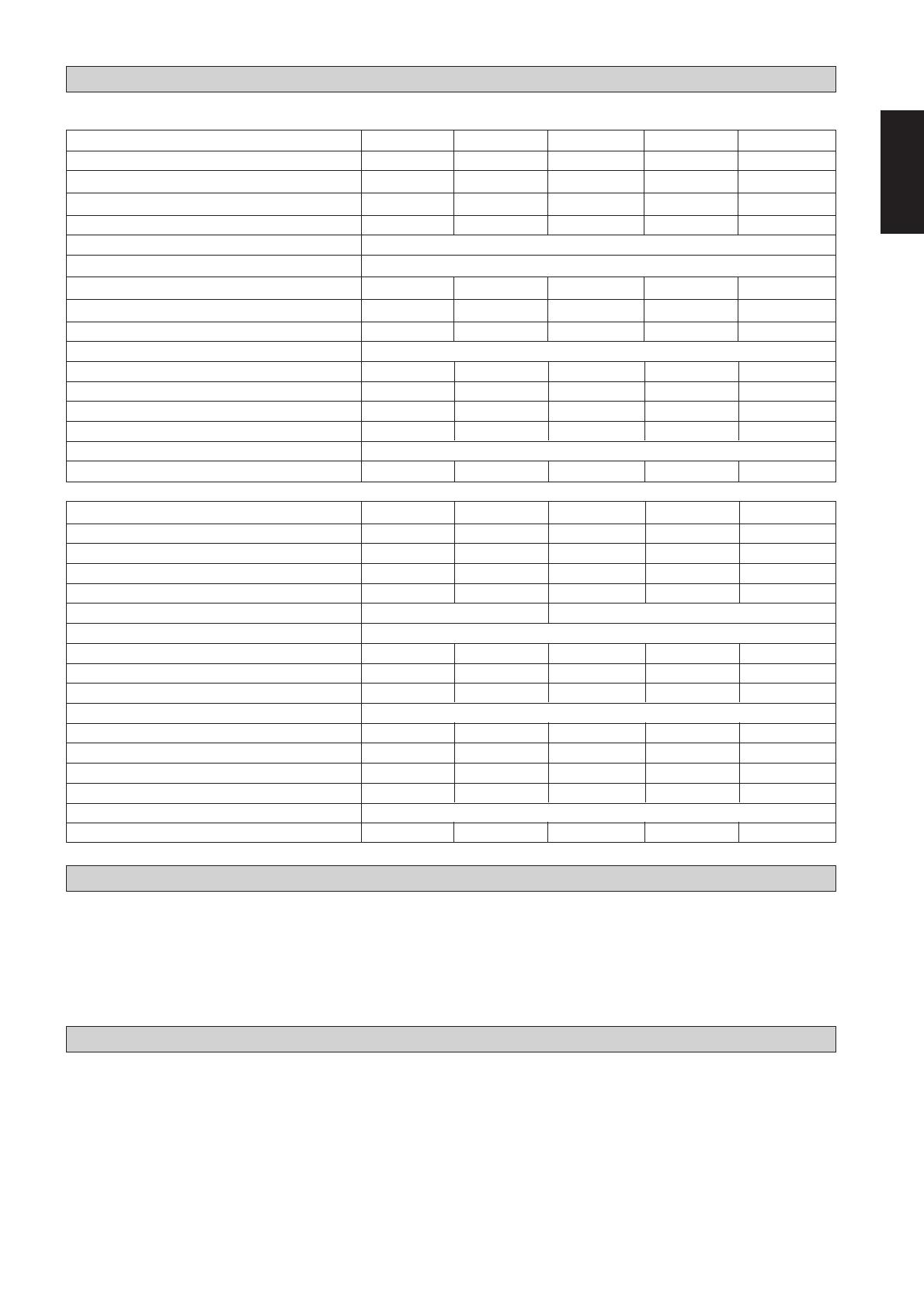
Acson 5WSS40AR Guide d'installation

Taper
Guide d'installation
Water Source Heat Pump
Split Type Air Conditioner
WSHP
INSTALLATION MANUAL
Model: IM-5WSS-1103-ACSON
Part Number: R08019029752
i
OUTLINE AND DIMENSIONS / DISPOSITION ET DIMENSIONS /
AUSLEGUNG UND ADMESSUNG / INGOMBRI E DIMENSIONI / ESQUEMA Y DIMENSIONES /
СХЕМА И РАЗМЕРЫ
700,0
572,096,0 32,0
317,0
357,0
774,0
A
All dimensions in mm
Figure 1
5WSS 07AR / 10AR / 15AR / 16AR / 20AR / 25AR
D
C
60,0
B
280,0
61,5
70,0
Model A B C D E F G H I J K L M N O
5WSS30AR 780 152 556 72 380 418,5 844 385 320 130 61,5 94 80 60 62
5WSS40AR 920 151 692 77 511 549,5 1020 440 450 130 61,5 102 100 80 75
5WSS50AR / 60AR 920 162 682 76 610 648,5 1020 504 550 130 61,5 107 100 80 75
A
C
B
D
E
F
H
G
ON M L
I
K
J
5WSS 30AR / 40AR / 50AR / 60AR
All dimensions in mm
Figure 2
Model A B C D
5WSS 07AR 300,0 55,0 55,0 51,5
5WSS 10AR / 15AR 330,0 55,0 70,0 61,5
5WSS 16AR / 20AR / 25AR 360,0 55,0 70,0 61,5
ii
All dimensions in mm
800
500
800
1200
Figure 3
INSTALLATION LOCATION / SÉLECTION DE L’EMPLACEMENT / INSTALLATION LAGE /
POSIZIONAMENTO ED INSTALLAZIONE / UBICACION DE LA UNIDAD /
МЕСТО УСТАНОВКИ
iii
Figure 4
5WSS 07AR / 10AR / 15AR / 16AR / 20AR / 25AR 5WSS 30AR / 40AR / 50AR / 60AR
BALANCING VALVE
ROBINET D’EQUILIBRAGE
DRUCKAUSGLEICHSVENTIL
VALVOLA DI BILANCIAMENTO
VÁLVULA DE EQUILIBRADO
БАЛАНСИРОВОЧНЫЙ КЛАПАН
Figure 5
1: SHUT OFF VALVE
SOUPAPE D’ARRET
SPERRVENTIL
VALVOLA DI CHIUSURA
LLAVE DE PASO
ОТСЕЧНОЙ КЛАПАН
2: WATER OUT
SORTIE D'EAU
WASSERABLAUF
ACQUA IN USCITA
AGUA FUERA
ВЫХОД ВОДЫ
3: WATER IN
ENTREE D'EAU
WASSERZULAUF
ACQUA IN ENTRATA
AGUA EN
ВХОД ВОДЫ
4: Y-STRAINER
EPURATEUR EN Y
Y-SIEB
FILTRO A Y
FILTRO-Y
У-ОБРАЗНЫЙ ФИЛЬТР
5: SHUT OFF VALVE
SOUPAPE D’ARRET
SPERRVENTIL
VALVOLA DI CHIUSURA
LLAVE DE PASO
ОТСЕЧНОЙ КЛАПАН
THREADED ROD
HEX. NUT
WASHER
VIBRATION ISOLATOR
1
2
3
4
5
WASHER
HEX. NUT
VIBRATION ISOLATOR
HEX. NUT
HEX. NUT
WASHER
WASHER
THREADED ROD
iv
Figure 7
Figure 8
1: VACUUM PUMP
POMPE À VIDE
VAKUUMPUMPE
POMPA A VUOTO
ESTRAER AIRE
ВАКУУМНЫЙ НАСОС
2: LIQUID VALVE
ROBINET DE LIQUIDE
FLÜSSIGKEITSVENTIL
VALVOLA LIQUIDO
VÁLVULA DEL LIQUIDO
ЖИДКОСТНОЙ ВЕНТИЛЬ
3: GAS VALVE (3-WAY)
ROBINET DE GAZ (3 DIRECTIONS)
GASVENTIL (3-WEGE)
VALVOLA GAS (A TRE VIE)
VÁLVULA DE GAS (3-DIRECCIONES)
ГАЗОВЫЙ ВЕНТИЛЬ (трехходовой)
=
2
3
HANDLE
Lo
POIGNÉE
Lo
SCHALTER
Lo
MANOPOLA
Lo
HANDLE
LO
КЛАПАН Низ
HANDLE
Hi
(ALWAYS CLOSED)
POIGNÉE
Hi
(TOUJOURS FERMÉE)
SCHALTER
Hi
(STETS GESCHLOSSEN)
MANOPOLA
Hi
(SEMPRE CHIUSA)
HANDLE
HI
(SIEMPRE CERRADO)
КЛАПАН Выс. (ВСЕГДА ЗАКРЫТ)
1
R
U
BBER B
USH
ENSURE WATER VALVE ADAPTORS ARE
ALIGNED TO THE CENTER WITHOUT TOUCHING
(min 2mm) THE RUBBER BUSH WHEN MAKING
PIPING CONNECTION.
Figure 6
v
1
5WSS 07AR / 10AR / 16AR / 20AR / 25AR
5WSS 15AR
SCHEMATIC DIAGRAM / SCHÉMA DE PRINCIPE / SCHEMATISCHE DARSTELLUNG /
DISEGNO SCHEMATICO / ESQUEMA / ПРИНЦИПИАЛЬНАЯ СХЕМА
Figure 9
Figure 10
2
3
4
5
!
6
$
5
&
%
1
2
3
4
7
11
8
7
$
9
COOLING OPERATION
HEATING OPERATION
7
8
7
SCHEMATIC DIAGRAM
6
&
%
SCHEMATIC DIAGRAM
COOLING OPERATION
HEATING OPERATION
11
)
(
)
(
vi
1
5WSS 30AR / 40AR / 50AR / 60AR
Figure 11
2
3
4
6
$
5
&
%
#
COOLING OPERATION
HEATING OPERATION
SCHEMATIC DIAGRAM
NOTE:
1. GAS PIPING / TUYAUTERIE DU GAZ / GASLEITUNG / TUBATURE DEL GAS / TUBOS DE GAS / ГАЗОВЫЙ ТРУБОПРОВОД
2. FAN COIL UNIT / VENTILO-CONVECTEUR / LUFTBEHANDLUNGSAGGREGAT / UNITÀ FAN COIL / VENTILOCONVECTOR /
ФАНКОЙЛ
3. FAN MOTOR / MOTEUR DU VENTILATEUR / GEBLÄSEMOTOR / MOTORE VENTOLA / MOTOR DE VENTILADOR /
ДВИГАТЕЛЬ ВЕНТИЛЯТОРА
4. LIQUID PIPING / TUYAUTERIE LIQUIDE / FLÜSSIGKEITSLEITUNG / TUBATURE DEL LIQUIDO / TUBOS DE LÍQUIDO /
ЖИДКОСТНЫЙ ТРУБОПРОВОД
5. 4 WAY VALVE / ROBINET A 4 VOIES / VIERWEGEVENTIL / VALVOLA A 4 VIE / VÁLVULA DE 4 VÍAS / 4-ХОДОВЫЙ ВЕНТИЛЬ
6. COMPRESSOR / COMPRESSEUR / KOMPRESSOR / COMPRESSORE / COMPRESOR / КОМПРЕССОР
7. STRAINER / EPURATEUR / SIEB / FILTRO / FILTRO / СЕТЧАТЫЙ ФИЛЬТР
8. COOLING & HEATING CAP. TUBE / TUYAUX CAP. REFRIGERATION ET CHAUFFAGE / KÜHL- UND HEIZKAPILLARROHR /
TUBO CAPILLARE RAFFREDDAMENTO & RISCALDAMENTO / TUBO CAP. DE REFRIGERACIÓN Y CALEFACCIÓN /
КАП. ТРУБКА ОХЛАЖДЕНИЯ И ОБОГРЕВА
9. COOLING CAP. TUBE / TUYAU CAP. REFRIGERATION / KÜHLKAPILLARROHR / TUBO CAPILLARE RAFFREDDAMENTO /
TUBO CAP. DE REFRIGERACIÓN / ЭЛЕКТРИЧЕСКИЕ СОЕДИНЕНИЯ
10. HEATING CAP. TUBE / TUYAU CAP. CHAUFFAGE / HEIZKAPILLARROHR / TUBO CAPILLARE RISCALDAMENTO /
TUBO CAP. DE CALEFACCIÓN / КАП. ТРУБКА ОБОГРЕВА
11. CHECK VALVE / CLAPET DE NON-RETOUR / ABSPERRVENTIL / VALVOLA DI NON RITORNO / VÁLVULA DE RETENCIÓN / АТ
12. THERMOSTATIC EXPANSION VALVE / DÉTENDEUR THERMOSTATIQUE / THERMOSTATISCHES EXPANSIONSVENTIL /
VALVOLA DI ESPANSIONE TERMOSTATICA / VÁLVULA TERMOSTÁTICA DE ESPANSIÓN / ТЕРМОРЕГУЛИРУЮЩИЙ ВЕНТИЛЬ
13.TUBE IN TUBE HEAT EXCHANGER / TUBE D’ECHANGEUR THERMIQUE / DOPPELROHRWÄRMETAUSCHER /
SCAMBIATORE DI CALORE TUBO IN TUBO / TUBO EN TERMOPERMUTADOR / ТЕПЛООБМЕННИК “ТРУБА В ТРУБЕ”
14. WATER INLET / PRISE D’ENTRÉE D’EAU / WASSEREINTRITTSÖFFNUNG / INGRESSO ACQUA / ENTRADA DEL AGUA /
ВОДОПРИЕМНИК
15. WATER OUTLET / PRISE DE SORTIE D’EAU / WASSERAUSTRITTSÖFFNUNG / USCITA ACQUA / SALIDA DEL AGUA /
ВОДОВЫПУСК
16. WATER SENSOR / CAPTEUR D’EAU / WASSERSENSOR / SENSORE ACQUA / SENSOR DEL AGUA / WATER SENSOR /
ДАТЧИК ВОДЫ
17. HIGH PRESSURE SWITCH / PRESSOSTAT HAUTE PRESSION / HOCHDRUCKSCHALTER / INTERRUTTORE ALTA PRESSIONE/
INTERRUPTOR DE ALTA PRESIÓN / ПЕРЕКЛЮЧАТЕЛЬ ВЫСОКОГО ДАВЛЕНИЯ
18. LOW PRESSURE SWITCH / PRESSOSTAT BASSE PRESSION / NIEDERDRUCKSCHALTER /
INTERRUTTORE BASSA PRESSIONE / INTERRUPTOR DE BAJA PRESIÓN / ПЕРЕКЛЮЧАТЕЛЬ НИЗКОГО ДАВЛЕНИЯ
19. TXV BY PASS CAP. TUBE / CONDENSATEUR DE DÉCOUPLAGE TXV / TXV BYPASS KAPILLARROHR /
TUBO COPERTO BY-PASS TXV / TXV POR PASS CAP. TUBO / TXV ОБХОД ЕМНОСТИ ТРУБКИ
77
+
)
~
(
vii
5WSS 20AR / 25AR
5WSS 07AR / 10AR / 15AR / 16AR
Figure 12
Figure 13
viii
5WSS 30AR
TH
HIGH PRESSURE
SWITCH
CM
C
R
S
4WV
A 4WV
COMP
N
Figure 14
LOW PRESSURE
SWITCH
5WSS 40AR / 50AR / 60AR
TH
HIGH PRESSURE
SWITCH
COMP.
4WV
A 4WV
COMP
LN
Figure 15
LOW PRESSURE
SWITCH
POWER SUPPLY 380-415V/3PH/50Hz
7A
CRANKCASE
HEATER
A1
A2
1L1 3L2 5L3 1
2T1 4T2 6T3 2
RS TN
POWER SUPPLY
220-240V / 1PH / 50Hz
English
This manual provides the procedures of installation to ensure a safe and good standard of operation for Water
Source Heat Pump split type unit.
Special adjustment may be necessary to suit local requirements.
Before using the Water Source Heat Pump split type unit, please read this instruction manual carefully and keep
it for future reference.
INSTALLATION MANUAL
WATER SOURCE HEAT PUMP SPLIT TYPE
AIR CONDITIONER
Part No.: R08019029752
MODEL
R410A
5WSS07AR / A5WSS07AR
5WSS10AR / A5WSS10AR
5WSS15AR / A5WSS15AR
5WSS16AR / A5WSS16AR
5WSS20AR / A5WSS20AR
5WSS25AR / A5WSS25AR
5WSS30AR / A5WSS30AR
5WSS40AR / A5WSS40AR
5WSS50AR / A5WSS50AR
5WSS60AR / A5WSS60AR
IM-5WSS-1103 (1)-Acson
! WARNING
Installation and maintenance should be performed by qualified persons who are familiar with local code and
regulation, and experienced with this type of appliance.
1-1
! CAUTION
Please take note of the following important points when installing.
Do not install the unit where leakage of flammable gas may occur.
If gas leaks and accumulates around the unit, it may cause fire ignition.
Do not overcharge the unit.
This unit is factory pre-charged. Overcharge will cause over-current or damage to the compressor.
INDEX
- Outline And Dimensions page i
- Installation Location page ii
- Schematic diagram page v
- Installation Location page 1
- Unit Installation page 1
- Physical Data page 2
- Water Piping And Fitting page 2
- Refrigerant Piping page 2
- Flare work page 3
- Vacuuming page 4
- Tightening Torque page 4
- Vacuuming And Charging page 4
- Electrical And Wiring page 5
- Electrical Data page 5
- Recommended Cable Sizes page 5
-
Special Precautions When Dealing With R410A Unit
page 6
- Control Operation Guide page 6
- Unit Operation Limits page 6
- System Cleaning And Flushing page 7
- Unit Start Up And Operation page 8
- Service And Maintenance page 8
- Troubleshooting page 9
INSTALLATION LOCATION
This unit is designed for indoor installation only.
Installation work should be done by authorized dealer or qualified contractor.
Install the unit at a suitable minimum distance or shortest path to the coupling fan coil unit.
There should be sufficient space for piping connection, service and maintenance. (Refer to Figure 3)
The area should be isolated from vibration and noise.
Ensure the area is free from water leakage.
UNIT INSTALLATION
This unit will be mounted on the ceiling by the support of four threaded rods. (Refer to Figure 4)
Ensure that the supports are strong enough and properly anchored to withstand the weight of the unit.
Use isolator rubber (natural rubber) with hardness of 35° for better noise and vibration control.
Do not locate the drainage system at any point above the drain connection.
1-2
English
PHYSICAL DATA
R410A - Heat Pump
Model 5WSS07AR 5WSS10AR 5WSS15AR 5WSS16AR 5WSS20AR
Nominal Cooling Capacity kW 2.37 2.93 3.58 4.63 6.01
Nominal Heating Capacity kW 2.58 3.08 3.75 4.63 6.74
Unit Weight kg 32.9 34.9 35.5 39.7 49.1
Refrigerant Charge R410A kg 0.600 0.600 0.700 0.725 0.975
Compressor Rotary Compressor
Refrigerant Circuit
Liquid valve connection inches 1/4 1/4 1/4 1/4 1/4
Gas valve connection inches 3/8 3/8 1/2 1/2 1/2
Service port connection (UNF-20) inches 1/2 1/2 1/2 1/2 1/2
Refrigerant - Water Heat Exchanger Tube In Tube
Water inlet (male) inches 1/2 1/2 1/2 1/2 1/2
Water outlet (male) inches 1/2 1/2 1/2 1/2 1/2
Water pressure drop kPa 5.36 5.88 8.12 10.35 14.54
Water flow rate m
3
/h 0.45 0.51 0.75 0.95 1.25
Drain Pipe Connection
Steel Pipe inches 3/4 3/4 3/4 3/4 3/4
Model 5WSS25AR 5WSS30AR 5WSS40AR 5WSS50AR 5WSS60AR
Nominal Cooling Capacity kW 7.62 2.37 2.93 3.58 4.63
Nominal Heating Capacity kW 7.80 2.58 3.08 3.75 4.63
Unit Weight kg 50.0 64.1 95.7 119.6 123.4
Refrigerant Charge R410A kg 1.000 1.200 1.475 1.950 2.300
Compressor Rotary Compressor Scroll Compressor
Refrigerant Circuit
Liquid valve connection inches 1/4 3/8 3/8 3/8 3/8
Gas valve connection inches 5/8 5/8 5/8 5/8 3/4
Service port connection (UNF-20) inches 1/2 1/2 1/2 1/2 1/2
Refrigerant - Water Heat Exchanger Tube In Tube
Water inlet (BSP)MALE inches 1/2 3/4 3/4 3/4 3/4
Water outlet (BSP)MALE inches 1/2 3/4 3/4 3/4 3/4
Water pressure drop kPa 19.03 30.59 9.49 9.59 18.84
Water flow rate m
3
/h 1.4 1.8 2.1 2.55 3.17
Drain Pipe Connection
Steel Pipe inches 3/4 3/4 3/4 3/4 3/4
WATER PIPING AND FITTING
Install a 40 – 60 mesh strainer to ensure water quality is good.
Water pipe materials recommended are black steel pipe and copper pipe.
All piping connections must be properly and firmly connected. Do not over-tighten the connections.
Users are recommended to install the pipes as shown in Figure 5 & 6.
The piping need to be cleaned and flushed prior to operation.
Air vents must be installed at the highest position while a drainage system at the lowest position of the water circuit.
REFRIGERANT PIPING
Do not use contaminated, dented or used copper tubing.
Do not use copper tubes with less than 0.8 mm thickness.
Use a flare tool specially for R410A.
Do not use mineral oil on flare part.
Use proper torque wrench to tight the flare nuts. If the torque strength is weak, gas leakage may occur. If it is too tight, the
flare nut may crack and it may be non-removable.
Use a vacuum pump with a back flow preventing adapter to prevent the vacuum pump oil mix with R410A which will
create sludge and damage the equipment.
Vacuum unit thoroughly to -76cmHg.
Insulate the piping to prevent capacity losses and water condensation.
1-3
!!
!!
! CAUTION
Connection service port at the gas valve is 1/2" UNF-20. It is different from the conventional R22 or R407C connec-
tion. This is to prevent wrong refrigerant charging into the system.
Beware that R410A standard operating pressure is about 1.6 times higher than R22.
Refrigerant Piping Length, Elevation And Bends
When piping length becomes too long, both the capacity and compressor reliability drop.
As the number of bends increases, system-piping resistance to the refrigerant flow increase thus lowering the capacity of the
unit and as a result the compressor may become defective.
Always choose the shortest path and follow the recommendation as tabulated below.
5WSS07AR 5WSS10AR 5WSS15AR 5WSS16AR 5WSS20AR
Max. Length, L 12 m 12 m 12 m 12 m 12 m
Max. Elevation, H 5 m 5 m 5 m 5 m 5 m
Max. No. of bends 10 10 10 10 10
Liquid Valve Size 6.35 mm (1/4") 6.35 mm (1/4") 6.35 mm (1/4") 6.35 mm (1/4") 6.35 mm (1/4")
Gas Valve Size 9.52 mm (3/8") 9.52 mm (3/8") 12.7 mm (1/2") 12.7 mm (1/2") 12.7 mm (1/2")
FLARE WORK
Use either a flare tool specially for R410A or a conventional type. Head project dimension may differ according to type of
flare tool.
Flare end diameter is also different for R410A. Flare section should be uniform or even. Crack on the flare section or burr
on the flare edge is not acceptable. Make new flare tubing again to prevent potential gas leak.
HEAD PROJECTION DIMENSION
Diameter A(mm)
in mm
Clutch Type Conventional
For R410A Clutch type
1/4 6.35 0 – 0.5 0.7 – 1.3
3/8 9.52 0 – 0.5 0.7 – 1.3
1/2 12.7 0 – 0.5 0.7 – 1.3
5/8 15.88 0 – 0.5 0.7 – 1.3
3/4 19.05 0 – 0.5 0.7 – 1.3
FLARE DIE
COPPER TUBE
COPPER TUBE
FLARE NUT
B
D
Diameter, D Flare End Diameter, B
in mm
1/4 6.35 9.1
3/8 9.52 13.2
1/2 12.7 16.6
5/8 15.88 19.7
3/4 19.05 24.0
Models gram/meter
5WSS07AR 18.5
5WSS10AR 18.5
5WSS15AR 18.5
5WSS16AR 18.5
5WSS20AR 18.5
5WSS25AR 18.5
5WSS30AR 18.5
5WSS40AR 47.5
5WSS50AR 47.5
5WSS60AR 47.5
Additional Charge
The pre-charged of R410 in the Water Source Heat Pump unit is suitable for standard pipe of length up:-
a) 2 meter for 5WSS07/10/15/16/20/25/30/40/50AR
b) 5 meter for 5WSS60AR
When the piping is more than the above stated standard pipe length, kindly add additional charge referring to the table below.
5WSS25AR 5WSS30AR 5WSS40AR 5WSS50AR 5WSS60AR
Max. Length, L 12 m 12 m 35 m 35 m 35 m
Max. Elevation, H 5 m 5 m 10 m 10 m 10 m
Max. No. of bends 10 10 10 10 10
Liquid Valve Size 6.35 mm (1/4") 9.52 mm (3/8") 9.52 mm (3/8") 9.52 mm (3/8") 9.52 mm (3/8")
Gas Valve Size 15.88 mm (5/8") 15.88 mm (5/8") 15.88 mm (5/8") 15.88 mm (5/8") 19.05 mm (3/4")
1-4
English
VACUUMING AND CHARGING
Use a vacuum pump with a back flow preventing adapter to prevent the vacuum pump oil mix with R410A which will
create sludge and damage the equipment. Use only gauge manifold exclusive for R410A for vacuuming and charging.
a) Gauge Manifold
Gauge Manifold (R410A) Connection Port Size
High Pressure Gauge (Red) -0.1 ~ 5.3 MPa
-76 cmHg ~ 53 kgf/cm
2
1/2 UNF -20
Low Pressure Gauge (Blue) -0.1 ~ 3.8 MPa
thread per inch
-76 cmHg ~ 38 kgf/cm
2
Charge Hose (R410A)
Operating Pressure 5.1 MPa (51 kgf/cm
2
)
Burst Pressure 27.4 MPa (274 kgf/cm
2
)
Connection size 1/2 UNF -20 thread per inch
b) Charge Hose
TIGHTENING TORQUE
Use proper torque wrench to tight the flare nuts. If the torque strength is weak, gas leakage may occur. If it is too tight, the flare
nut may crack and it may be non-removable.
Diameter
Torque (Nm)
in mm
1/4 6.35 18
3/8 9.52 42
1/2 12.7 55
5/8 15.88 65
3/4 19.05 100
Unit has to be sufficiently vacuumed to -0.1MPa (-76cmHg). Leave the vacuum for 5 minutes to ascertain the gauge pointer
do not raise again. (Refer to Figure 7 & 8)
VACUUMING
The different size of connection port from the conventional is to prevent wrong refrigerant charging instead of R410A.
c) Refrigerant Cylinder
A typical R410A charging cylinder will be identified with the refrigerant name and is coated with pink in colour as designated
by ARI.
R410A is mixture of refrigerant which have different evaporating temperature. So when charging, make sure only liquid is
being withdrawn from the charging cylinder. Charging gas refrigerant R410A in state will affect the performance and operat-
ing condition of the system. Invert the cylinder that does not come with dip pipe during charging.
Additional Charge Operation
This operation must be done by using a gas cylinder and a precise weighing machine. The additional charge is topped-up into
the outdoor unit using the suction valve via service port.
- Remove the service port cap.
- Connect the low pressure side of the charging gauge to the suction service port, center of the cylinder tank and close the
high pressure side of the gauge. Purge the air from the service hose.
- Start the air conditioner unit.
- Open the gas cylinder and low pressure charging valve.
- When the required refrigerant quantity is pumped into the unit, close the low pressure side and the gas cylinder valve.
- Disconnect the service hose from service port. Put back the service port cap.
1-5
RECOMMENDED CABLE SIZES
ELECTRICAL DATA
!!
!!
! CAUTION
Ensure the rated voltage and phase of the unit corresponds to the unit name plate before carrying out wiring work.
The unit must be GROUNDED to prevent hazards due to insulation failures.
Do not ground any electrical equipment to the water piping.
Ensure all electrical wiring do not touch the refrigerant piping, compressor, pump or any moving parts.
Do not operate unit with wet hand(s). It will result in electrical shock.
Model 5WSS07AR 5WSS10AR 5WSS15AR 5WSS16AR 5WSS20AR
Rated Voltage Range**
220-240/1Ph/50Hz
Supply Cable Size
mm
2
1.5 1.5 1.5 1.5 2.5
Number of Cables
333 33
Interconnection Cable Size*
mm
2
1.5 1.5 1.5 1.5 2.5
Number of Cables
555 55
Heat Pump
Model 5WSS25AR 5WSS30AR 5WSS40AR 5WSS50AR 5WSS60AR
Rated Voltage Range**
220-240/1Ph/50Hz 380-415/3Ph/50Hz
Supply Cable Size
mm
2
2.5 4.0 2.5 2.5 2.5
Number of Cables
335 55
Interconnection Cable Size*
mm
2
2.5 4.0 1.5 1.5 1.5
Number of Cables
556 66
ELECTRICAL AND WIRING
Refer to the wiring diagram provided on the unit when making electrical wiring connection. (Refer to Figure 12, 13, 14 & 15)
Power supply is from fan coil unit connection.
All field wiring must comply with your national or local wiring regulation.
All terminal wiring must be firmly connected. Improper connection can cause electric shock, short circuit or fire breakout.
A circuit breaker must be provided for over current protection.
All safety precautions need to be strictly adhere.
R410A - HEAT PUMP
Model 5WSS07AR 5WSS10AR 5WSS15AR 5WSS16AR 5WSS20AR
Power Supply
V/Ph/Hz
220-240/1/50
Nominal Power Input (Cooling) W 502 642 916 980 1370
Nominal Power Input (Heating) W 512 662 906 940 1520
Nominal Current (Cooling) A 2.3 2.8 4.4 4.4 6.1
Nominal Current (Heating) A 2.3 2.9 4.3 4.3 6.8
Capacitor (440 VAC) µf2030253050
Model 5WSS25AR 5WSS30AR 5WSS40AR 5WSS50AR 5WSS60AR
Power Supply
V/Ph/Hz
220-240/1/50 380-415/3/50
Nominal Power Input (Cooling) W 1444 1967 2485 3101 3629
Nominal Power Input (Heating) W 1594 2047 2475 3041 3329
Nominal Current (Cooling) A 6.5 9.8 4.8 5.8 6.9
Nominal Current (Heating) A 7.2 10 4.7 5.7 6.6
Capacitor (440 VAC) µf50 45 - - -
Fuse Amp - - 7 7 7
1-6
English
UNIT OPERATION LIMITS
Environment
This unit is designed for indoor installation and operation only. This unit also limited to water loop application only as the heat
exchanger can only cater for this application.
Power Supply
A voltage variation of +/- 10% of rated voltage stated in the unit label is acceptable.
Allowable Operation Conditions
Ensure the operating temperature and condition are in allowable range. Extreme variations in temperature, humidity and
corrosive water or air will adversely affect unit performance, reliability and service life.
CONTROL OPERATION GUIDE
Controller of water source heat pump split type unit is located in the fan coil unit.
Refer to fan coil unit installation manual for control guide operation.
!!
!!
! CAUTION
R410A must be charged in liquid phase. Usually R410A cylinder is equipped with a dip pipe for liquid withdrawal. If
there is no dip pipe, invert the cylinder to withdraw R410A liquid.
If leak occurs, do not top-up any additional R410A refrigerant as this will reduce the unit performance. Instead
evacuate the refrigerant and fix the leakage before vacuuming it thoroughly. Then charge with new R410A refriger-
ant according to the recommended specification.
If refrigerant gas leak occurs during installation / servicing, make sure the area is ventilate fully.
Do not allow the piping and unit exposed to air or moisture.
Install a bi-flow filter dryer (two way) along the liquid line.
Heat Pump
Water Entering Temp. (
o
C)
Water Entering Temp. (
o
C)
32
20
12
45
30
13
STD
Heating Cooling
Indoor Temp. (
o
C DB)
15 20 27 15 19 24
STD
Indoor Temp. (
o
C WB)
SPECIAL PRECAUTIONS WHEN DEALING WITH R410A UNIT
R410A is a near azeotrope refrigerant mixture of hydro fluorocarbon (HFC) which is environmental friendly. It has Zero
Ozone Depletion Potential (ODP=0) and this conform to Montreal Protocol regulations.
R410A system has a operating pressure of about 1.6 times higher than R22 at the same temperature.
Never use copper tubes thinner than 0.8mm.
R410A compressor uses polyol-ester oil (POE) as lubricant which is prone to moisture contamination (hydroscopic).
Hydrolysis may occur that will generate acid when mix with moisture or water and will damage the compressor winding.
It has to be treated in a more cautiously manner than other conventional mineral oil.
Do not expose the system for too long. POE oil will absorb moisture into the system that will generate acid and cause
capillary clogging or compressor motor winding damage. Cover temporary the refrigerant valve or copper tube opening
when performing installation or servicing. Install a bi-flow filter dryer (two-way) along the liquid piping to absorb the
unwanted moisture. Residue POE oil in the piping and components can absorb moisture from the air.
Do not mix R410A with other refrigerant into the system.
Identified refrigerant before charging. R410A refrigerant cylinder is pink coated. Charge only R410A liquid phase into the units.
Do not add any additional oil into the compressor.
Use only exclusive tools and equipment for R410A:
i) Manifold gauge and charging hose
ii) Gas leak detector
iii) Refrigerant cylinder (usually pink coated)
iv) Vacuum pump c/w adaptor
v) Flare tools
vi) Refrigerant recovery machine
1-7
Water Pressure Drop Table
Model Water Flow Rate Pressure Drop
m
3
/hr kPa
0.2 3.71
5WSS07AR 0.4 5.00
0.6 6.65
0.3 4.28
5WSS10AR 0.5 5.80
0.7 7.63
0.5 5.80
5WSS15AR 0.7 7.63
0.9 9.72
0.7 2.93
5WSS16AR 0.9 4.58
1.1 7.46
1.0 13.06
5WSS20AR 1.2 15.35
1.4 19.03
The water circulating loop system must be cleaned and flushed to remove all construction debris and dirts before operating the units.
1. If the connection is equipped with water shut-off valve, either electric or pressure operated, the individual supply and
return pipes must be connected together first. This will prevent the introduction of dirt into the unit.
2. Fill the water loop system with your local water supply with all air vents open. After filling, close all air vents. The
contractor should start the main circulator pump with the pressure reducing valve open. Check all vents in sequence to
bleed off any trapped air, ensuring circulation through all components of the system. Power to the heat rejector unit should
be off and the supplementary heat control set at 27
o
C (80
o
F).
3. While the water is circulating, the contractor should check and repair any leaks in the piping. Drains at the lowest point(s)
in the system should be opened for initial flush and blow down. Make sure the local supply water valves are set to make up
for the required flow rate. Check the pressure gauge at the pump suction and manually adjust the make up to hold the same
positive steady pressure both before and after opening the drain valves. Flush should be continuously for two hours or
longer if required to obtain a clean and clear drain water.
4. Shut off all supplemental heater and circulator pump and open all drains and vents to complete drain down the system.
Now, the short-circuited water connection to the supply and return pipes should be removed and connected to the indi-
vidual water inlet and outlet of the unit. Use proper tape to seal off at the valve connection. Do not use sealant at the valves
connection.
5. Trisodium phosphate was formerly recommended as a cleaning agent during flushing. However, some of the local authori-
ties ban the usage of the phosphate into the sewage systems. The current recommendation is to simply flush longer with
warm at 27
o
C (80
o
F) water.
6. Refill the water loop system with clean water. Test the water for acidity by using a litmus paper. Treat the water if required
to obtain the pH level between 7.5 to 8.5 (slightly alkaline). If antifreeze is required, use only antifreeze designed for
HVAC. Do not use automotive grade antifreeze.
7. Once the water system is ready, ensure at all times only clean water is supply to the system. Dirty water will result in wide
degradation of performance and solids may clog valves, strainers, flow regulator, etc. Pump work will increase and may
damage the pumps. The heat exchanger may become clogged as well which will reduce the compressor service life or
causes premature failure.
8. Finally set the loop water controller heat addition point to 21
o
C (70
o
F) and the heat rejection set point to 29
o
C (85
o
F).
Supply power to all motors and start the circulating pumps. After full flow has been established through all components
including heat rejector (regardless of season) and air vented and loop temperature stabilized, each of the air conditioners
will be ready for check, test and start up, air balancing and water balancing.
SYSTEM CLEANING AND FLUSHING
Model Water Flow Rate Pressure Drop
m
3
/hr kPa
1.2 14.86
5WSS25AR 1.4 19.46
1.6 23.72
1.6 24.76
5WSS30AR 1.8 30.59
2 36.42
1.9 7.53
5WSS40AR 2.1 9.49
2.3 12.03
2.3 6.67
5WSS50AR 2.5 8.98
2.7 11.83
3 16.31
5WSS60AR 3.2 19.28
3.4 22.21
1-8
English
1. Make sure all wiring connection is correct and power supply is compatible to the rated voltage.
2. Open all valves in full open position and start the circulating pump. Make sure there is water running through the water
loop before operating the unit.
3. Set to mode ‘Cool’. Then set the temperature to the coolest. The unit has time delay which protects the compressor for
short cycling. Wait for a few minutes before check on the air discharge for cool air delivery.
4. Measure the temperature difference between entering and leaving water. It should before approximately 1.3 to 1.5 times
greater than the heating mode temperature difference.
Example: If water temperature difference in cooling mode is 5°C (9°F), the heating mode difference should be 3.3°C
(6°F).
5. If without automatic flow control valves, target the cooling mode water temperature difference between 5°C (9°F) to 8°C
(14.4°F). This can be achieved by adjusting shut-off / balancing valve in the return piping to a suitable water flow rate to
achieve the desire temperature difference.
6. Set to mode ‘Heat’. Set the temperature to the warmest. Again the air conditioner has built in time delay that prevents the
compressor to start immediately. The fan will start first before the compressor. Check for warm air discharge. If it is a ‘cold
building’ start-up, leave the unit running until return air to the unit is at least 18°C (65°F).
7. Measure the temperature difference between entering and leaving water. With entering water temperature of 16°C to 27°C
(60°F to 80°F), leaving water temperature should be 3.3°C to 6°C (6°F to 12°F) cooler and the air temperature rise through
the machine should not exceed 19°C (35°F). If the air temperature exceeds 19°C (35°F), then the water flow rate is
inadequate.
8. Check for vibration refrigerant piping, fan wheels, etc.
NOTE
Water source heat pump split type unit is controlled by fan coil unit.
The controller is located on the fan coil unit.
!!
!!
! CAUTION
Ensure there is water supply into the unit at all times before operating.
UNIT START UP AND OPERATION
SERVICE AND MAINTENANCE
Service and maintenance should be performed by authorized dealer or qualified contractor.
Internal components can be accessed through two service panels (front and back). External control box for easy access of
electrical components.
Regular checks on the water strainer are recommended. Clean the strainer if dirty or clogged.
Maintain a log data on measurement of volts, amps, and water temperature difference (heating & cooling) is recommended.
A comparison of the data during start-up and periodic data is useful as indicator of general condition of equipment.
!!
!!
! CAUTION
Do not attempt to do any service or maintenance when the unit is operating.
Unauthorized modification of the unit is not allowed.
1-9
TROUBLESHOOTING
Troubleshooting must be performed by authorized dealer or qualified contractor.
Fault Cause / Check Point
Unit cannot start 1. Power supply plug disconnected.
2. Circuit breaker or fuse tripped / blown.
3. Wiring connection
4. If fault persist, contact your installer.
Neither fan coil unit and 1. The fuse may be blown or circuit breaker opened.
compressor run 2. Check electrical circuit or motor winding for shorts or grounds. Investigate for
possible over loading. Replace fuse if necessary.
3. Check wiring connections. Wire may be loosening. Replace or tighten.
4. Control system may be faulty.
Compressor does not 1. Check capacitor if available. Replace capacitor if faulty.
operate. 2. Check wiring connection. Wire may be loosening. Replace or tighten.
3. The high pressure switch may tripped due to:
a) No or insufficient water flows into and leaves heat exchanger. May be clogged.
b) Water entering temperature higher than the maximum operating conditions.
c) Not enough air flow into fan coil unit. May be due to dirty filter or block by object,
cardboard and etc (heating mode).
d) Fan coil motor failure (heating mode).
e) Unit over-charged. Release some of the refrigerant charge.
4. The compressor internal/external overload protection is opened. If the compressor body
is extremely hot, the overload will not reset until it cooled down.
5. The compressor winding may be grounded to the compressor shell. If so, replace
the compressor.
Insufficient cooling 1. Check controller temperature setting.
or heating. 2. Filter may be clogged. Check and clean the filter.
3. Check capillary tube for possible restriction of refrigerant flow. Replace capillary tube
if proven so.
4. The reversing valve may be defective (valve position is not shifted properly), creating
a bypass of refrigerant. Check the reversing valve coil connection.
5. Check for restriction of air and water flow.
6. Refrigerant leakage. Check all piping bends and connection for leakage. Repair the
leakage area or replace with new piping.
7. Window or door wide open.
8. Unit may be under-sized.
Insufficient water flow 1. Valves are not opened fully.
through heat exchanger 2. Circulating water pump is faulty.
3. Water pipes or strainers are clogged.
Noisy operation 1. Check for loose bolts or screws.
2. Make sure rubber isolators are used for installation.
3. Check for water balance to unit for proper water flow rate.
4. Check for tubing touching compressor or other surface. Readjust tubing by bending
it slightly.
5. Fan (fan coil unit) knocking / hitting on its housing.
6. May be due to worn compressor bearing.
  • Page 1 1
  • Page 2 2
  • Page 3 3
  • Page 4 4
  • Page 5 5
  • Page 6 6
  • Page 7 7
  • Page 8 8
  • Page 9 9
  • Page 10 10
  • Page 11 11
  • Page 12 12
  • Page 13 13
  • Page 14 14
  • Page 15 15
  • Page 16 16
  • Page 17 17
  • Page 18 18
  • Page 19 19
  • Page 20 20
  • Page 21 21
  • Page 22 22
  • Page 23 23
  • Page 24 24
  • Page 25 25
  • Page 26 26
  • Page 27 27
  • Page 28 28
  • Page 29 29
  • Page 30 30
  • Page 31 31
  • Page 32 32
  • Page 33 33
  • Page 34 34
  • Page 35 35
  • Page 36 36
  • Page 37 37
  • Page 38 38
  • Page 39 39
  • Page 40 40
  • Page 41 41
  • Page 42 42
  • Page 43 43
  • Page 44 44
  • Page 45 45
  • Page 46 46
  • Page 47 47
  • Page 48 48
  • Page 49 49
  • Page 50 50
  • Page 51 51
  • Page 52 52
  • Page 53 53
  • Page 54 54
  • Page 55 55
  • Page 56 56
  • Page 57 57
  • Page 58 58
  • Page 59 59
  • Page 60 60
  • Page 61 61
  • Page 62 62
  • Page 63 63
  • Page 64 64
  • Page 65 65
  • Page 66 66
  • Page 67 67
  • Page 68 68
  • Page 69 69
  • Page 70 70
  • Page 71 71
  • Page 72 72
  • Page 73 73
  • Page 74 74
  • Page 75 75
  • Page 76 76
  • Page 77 77
  • Page 78 78
  • Page 79 79
  • Page 80 80
  • Page 81 81
  • Page 82 82
  • Page 83 83
  • Page 84 84
  • Page 85 85
  • Page 86 86
  • Page 87 87
  • Page 88 88
  • Page 89 89
  • Page 90 90
  • Page 91 91
  • Page 92 92
  • Page 93 93
  • Page 94 94

Acson 5WSS40AR Guide d'installation

Taper
Guide d'installation