24A06G-124A06G-1
24A06G-124A06G-1
24A06G-1
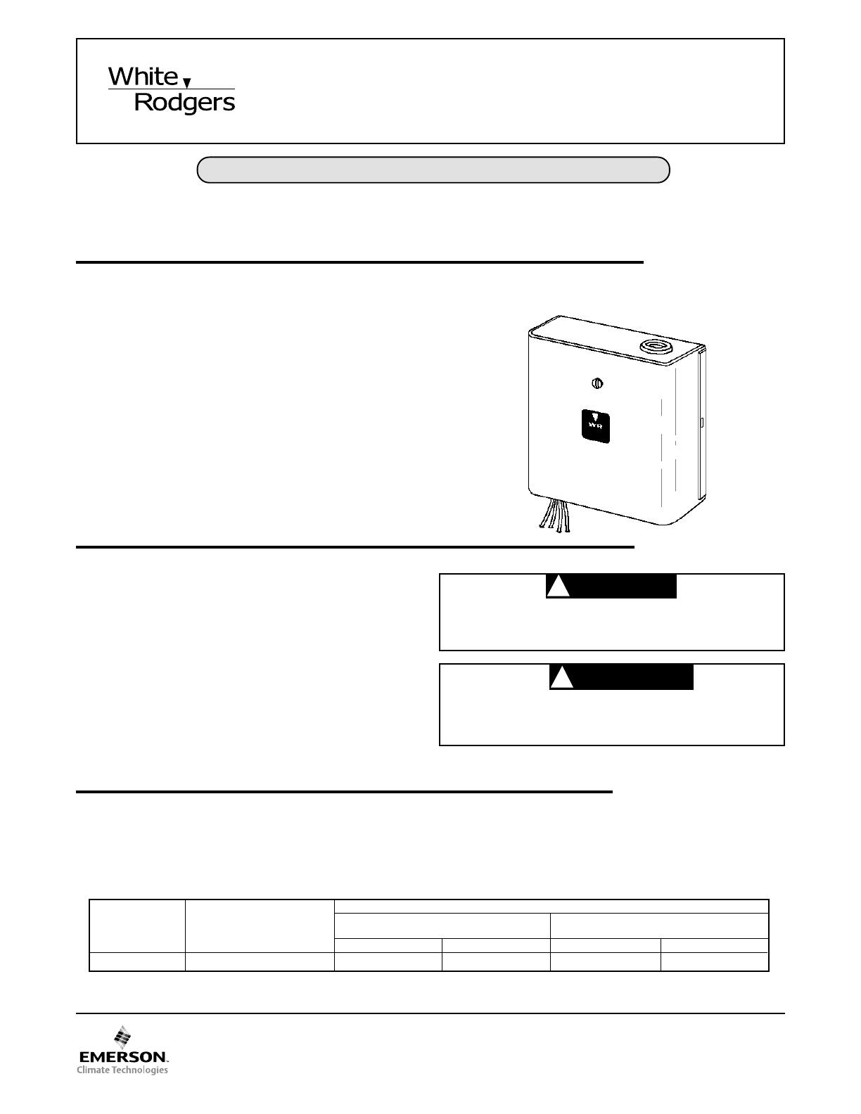
DUAL LEVEL-TEMP
SILENT OPERATOR RELAY
(Normally Open Contacts)
PART NO. 37-4165CPART NO. 37-4165C
PART NO. 37-4165CPART NO. 37-4165C
PART NO. 37-4165C
Replaces 37-4165B
0504
INSTALLATION INSTRUCTIONSINSTALLATION INSTRUCTIONS
INSTALLATION INSTRUCTIONSINSTALLATION INSTRUCTIONS
INSTALLATION INSTRUCTIONS
Operator: Save these instructions for future use!Operator: Save these instructions for future use!
Operator: Save these instructions for future use!Operator: Save these instructions for future use!
Operator: Save these instructions for future use!
FAILURE TO READ AND FOLLOW ALL INSTRUCTIONS CAREFULLY BEFOREFAILURE TO READ AND FOLLOW ALL INSTRUCTIONS CAREFULLY BEFORE
FAILURE TO READ AND FOLLOW ALL INSTRUCTIONS CAREFULLY BEFOREFAILURE TO READ AND FOLLOW ALL INSTRUCTIONS CAREFULLY BEFORE
FAILURE TO READ AND FOLLOW ALL INSTRUCTIONS CAREFULLY BEFORE
INSTALLING OR OPERATING THIS CONTROL COULD CAUSE PERSONALINSTALLING OR OPERATING THIS CONTROL COULD CAUSE PERSONAL
INSTALLING OR OPERATING THIS CONTROL COULD CAUSE PERSONALINSTALLING OR OPERATING THIS CONTROL COULD CAUSE PERSONAL
INSTALLING OR OPERATING THIS CONTROL COULD CAUSE PERSONAL
INJURY AND/OR PROPERTY DAMAGE.INJURY AND/OR PROPERTY DAMAGE.
INJURY AND/OR PROPERTY DAMAGE.INJURY AND/OR PROPERTY DAMAGE.
INJURY AND/OR PROPERTY DAMAGE.
PRECAUTIONSPRECAUTIONS
PRECAUTIONSPRECAUTIONS
PRECAUTIONS
To prevent electrical shock and/or equipment damage,To prevent electrical shock and/or equipment damage,
To prevent electrical shock and/or equipment damage,To prevent electrical shock and/or equipment damage,
To prevent electrical shock and/or equipment damage,
disconnect electric power to system at main fuse ordisconnect electric power to system at main fuse or
disconnect electric power to system at main fuse ordisconnect electric power to system at main fuse or
disconnect electric power to system at main fuse or
circuit breaker box until installation is complete.circuit breaker box until installation is complete.
circuit breaker box until installation is complete.circuit breaker box until installation is complete.
circuit breaker box until installation is complete.
CAUTION
!
WARNING
!
Do not use on circuits exceeding specified voltage.Do not use on circuits exceeding specified voltage.
Do not use on circuits exceeding specified voltage.Do not use on circuits exceeding specified voltage.
Do not use on circuits exceeding specified voltage.
Higher voltage will damage control and could causeHigher voltage will damage control and could cause
Higher voltage will damage control and could causeHigher voltage will damage control and could cause
Higher voltage will damage control and could cause
shock or fire hazard.shock or fire hazard.
shock or fire hazard.shock or fire hazard.
shock or fire hazard.
This Dual Level-Temp Silent Operator Relay is designed for
controlling two separate loads with a single low voltage
thermostat. It is especially suitable for use with electric heating
equipment.
The Dual Level-Temp relay may be used to operate two
separate heating loads by means of a single low voltage
thermostat. It is equally well suited for use with a heating-
cooling thermostat to control heating and cooling loads alter-
nately as in motels, apartments, office buildings, etc.
This model Dual Level-Temp relay has a voltage input of 240
volts. Since this relay is equipped with a self-contained trans-
former, the supply voltage used must agree with the voltage
rating of the relay. This model has both an inductive and non-
inductive rating.
If in doubt about whether your wiring is millivolt, line, or low
voltage, have it inspected by a qualified heating and air
conditioning contractor, electrician, or someone familiar with
basic electricity and wiring.
Do not exceed the specification ratings.
All wiring must conform to local and national electrical codes
and ordinances.
This control is a precision instrument, and should be handled
carefully. Rough handling or distorting components could
cause the control to malfunction.
DESCRIPTIONDESCRIPTION
DESCRIPTIONDESCRIPTION
DESCRIPTION
SPECIFICATIONSSPECIFICATIONS
SPECIFICATIONSSPECIFICATIONS
SPECIFICATIONS
ELECTRICAL DATAELECTRICAL DATA
ELECTRICAL DATAELECTRICAL DATA
ELECTRICAL DATA
Switch Action:Switch Action:
Switch Action:Switch Action:
Switch Action: Two SPST switches, normally open
Thermal:Thermal:
Thermal:Thermal:
Thermal: Average time delay – 45 seconds
Ambient Temperature:Ambient Temperature:
Ambient Temperature:Ambient Temperature:
Ambient Temperature: -20° to 120°F (-24° to 49°C)
Mounting:Mounting:
Mounting:Mounting:
Mounting: 1/2" conduit hub or two key slot mounting holes
Thermostat Circuit Current:Thermostat Circuit Current:
Thermostat Circuit Current:Thermostat Circuit Current:
Thermostat Circuit Current:
Bimetal Heater #1 (Red & White Leads)Bimetal Heater #1 (Red & White Leads)
Bimetal Heater #1 (Red & White Leads)Bimetal Heater #1 (Red & White Leads)
Bimetal Heater #1 (Red & White Leads) –
0.21 Amps
Bimetal Heater #2 (Red & Black with White StripeBimetal Heater #2 (Red & Black with White Stripe
Bimetal Heater #2 (Red & Black with White StripeBimetal Heater #2 (Red & Black with White Stripe
Bimetal Heater #2 (Red & Black with White Stripe
Leads)Leads)
Leads)Leads)
Leads) –
0.21 Amps
The Silent Operator relay has been carefully adjusted at the
factory, and no attempt should be made to adjust them in the
field.
TYPE INPUT
NUMBER VOLTAGE /FREQUENCY
ELECTRICAL RATING
FOR SWITCH #1 FOR SWITCH #2
(Red and Black Leads) (Red Striped and Black Striped Leads)
NON-INDUCTIVE INDUCTIVE* NON-INDUCTIVE INDUCTIVE*
24A06G-1 240VAC, 60 Hz 25A, 6000W 12 FLA (72 LRA) 25A, 6000W 12 FLA (72 LRA)
*FLA - Full Load Amps.; LRA - Locked Rotor Amps.
White-Rodgers is a division
of Emerson Electric Co.
www.white-rodgers.com


