Simplicity 030488-0 Manuel utilisateur
- Catégorie
- Groupes électrogènes
- Taper
- Manuel utilisateur
Ce manuel convient également à

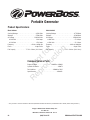
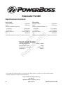
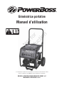
Portable Generator
Operator’s Manual
BRIGGS & STRATTON POWER PRODUCTS GROUP, LLC
MILWAUKEE, WISCONSIN, U.S.A.
Manual No. 311866GS Revision -
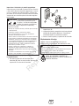
This generator is rated in accordance with CSA (Canadian Standards
Association) standard C22.2 No. 100-04 (motors and generators).
Not for
Reproduction

2 BRIGGSandSTRATTON.COM
Copyright © 2009. Briggs & Stratton Power Products Group, LLC
Milwaukee, WI, USA. All rights reserved.
BRIGGS & STRATTON POWER PRODUCTS is a registered
trademark of Briggs & Stratton Corporation
Milwaukee, WI, USA
Thank you for purchasing this quality-built Briggs & Stratton generator. We are pleased that you’ve placed your confidence in
the PowerBoss® brand. When operated and maintained according to the instructions in this manual, your Briggs & Stratton
generator will provide many years of dependable service.
This manual contains safety information to make you aware of the hazards and risks associated with generator products and
how to avoid them. This generator is designed and intended only for supplying electrical power for operating compatible
electrical lighting, appliances, tools and motor loads, and is not intended for any other purpose. It is important that you read
and understand these instructions thoroughly before attempting to start or operate this equipment. Save this original manual
for future reference.
This generator requires final assembly before use. Refer to the Assembly section of this manual for instructions on final
assembly procedures. Follow the instructions completely.
Where to Find Us
You never have to look far to find Briggs & Stratton support and service for your generator. Consult your Yellow Pages. There
are over 30,000 Briggs & Stratton authorized service dealers worldwide who provide quality service. You can also contact
Briggs & Stratton Customer Service by phone at (800) 743-4115, or on the Internet at BRIGGSandSTRATTON.COM. For
engine related questions, call American Honda Motor Company, Inc. at (800) 426-7701 or visit www.honda-engines.com for a
dealer locator.
Generator
Model Number
Revision
Serial Number
Date Purchased
Not for
Reproduction

3
Table of Contents
Operator Safety . . . . . . . . . . . . . . . . . . . . . . . . . . . . . . . . . 4
Equipment Description. . . . . . . . . . . . . . . . . . . . . . . . . . . . . . . . . . . . . . . . . 4
Important Safety Information. . . . . . . . . . . . . . . . . . . . . . . . . . . . . . . . . . . . 4
Assembly . . . . . . . . . . . . . . . . . . . . . . . . . . . . . . . . . . . . . 7
Unpack Generator . . . . . . . . . . . . . . . . . . . . . . . . . . . . . . . . . . . . . . . . . . . . 7
Shipment Contents . . . . . . . . . . . . . . . . . . . . . . . . . . . . . . . . . . . . . . . . . . . 7
Install Wheel Kit. . . . . . . . . . . . . . . . . . . . . . . . . . . . . . . . . . . . . . . . . . . . . . 7
Moving Generator . . . . . . . . . . . . . . . . . . . . . . . . . . . . . . . . . . . . . . . . . . . . 8
Add Engine Oil . . . . . . . . . . . . . . . . . . . . . . . . . . . . . . . . . . . . . . . . . . . . . . . 8
Add Fuel. . . . . . . . . . . . . . . . . . . . . . . . . . . . . . . . . . . . . . . . . . . . . . . . . . . . 8
System Ground . . . . . . . . . . . . . . . . . . . . . . . . . . . . . . . . . . . . . . . . . . . . . . 9
Connecting to a Building’s Electrical System. . . . . . . . . . . . . . . . . . . . . . . . 9
Generator Location . . . . . . . . . . . . . . . . . . . . . . . . . . . . . . . . . . . . . . . . . . . 9
Features and Controls . . . . . . . . . . . . . . . . . . . . . . . . . . . . 10
Cord Sets and Receptacles . . . . . . . . . . . . . . . . . . . . . . . . . . . . . . . . . . . . 11
Ground Fault Protection. . . . . . . . . . . . . . . . . . . . . . . . . . . . . . . . . . . . . . . 12
Operation . . . . . . . . . . . . . . . . . . . . . . . . . . . . . . . . . . . . 13
Starting the Engine . . . . . . . . . . . . . . . . . . . . . . . . . . . . . . . . . . . . . . . . . . 13
Connecting Electrical Loads. . . . . . . . . . . . . . . . . . . . . . . . . . . . . . . . . . . . 13
Stopping the Engine. . . . . . . . . . . . . . . . . . . . . . . . . . . . . . . . . . . . . . . . . . 14
Operating Automatic Idle Control. . . . . . . . . . . . . . . . . . . . . . . . . . . . . . . . 14
Using the Center Point Lift. . . . . . . . . . . . . . . . . . . . . . . . . . . . . . . . . . . . . 14
Don’t Overload Generator . . . . . . . . . . . . . . . . . . . . . . . . . . . . . . . . . . . . . 15
Maintenance . . . . . . . . . . . . . . . . . . . . . . . . . . . . . . . . . . 16
General Recommendations . . . . . . . . . . . . . . . . . . . . . . . . . . . . . . . . . . . . 16
Generator Maintenance . . . . . . . . . . . . . . . . . . . . . . . . . . . . . . . . . . . . . . . 16
Engine Maintenance. . . . . . . . . . . . . . . . . . . . . . . . . . . . . . . . . . . . . . . . . . 17
Storage . . . . . . . . . . . . . . . . . . . . . . . . . . . . . . . . . . . . . . . . . . . . . . . . . . . 18
Troubleshooting . . . . . . . . . . . . . . . . . . . . . . . . . . . . . . . . 19
Schematic - Model 030488 (5500 Watt) . . . . . . . . . . . . . . . . . . . . . . . . . . 20
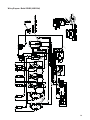
Wiring Diagram - Model 030488 (5500 Watt). . . . . . . . . . . . . . . . . . . . . . 21
Schematic - Model 030489 (6500 Watt) . . . . . . . . . . . . . . . . . . . . . . . . . . 22
Wiring Diagram - Model 030489 (6500 Watt). . . . . . . . . . . . . . . . . . . . . . 23
Warranties. . . . . . . . . . . . . . . . . . . . . . . . . . . . . . . . . . . . 24
Generator Owner Warranty . . . . . . . . . . . . . . . . . . . . . . . . . . . . . . . . . . . . 24
Specifications . . . . . . . . . . . . . . . . . . . . . . . . . . . . . . . . . 28
Product Specifications. . . . . . . . . . . . . . . . . . . . . . . . . . . . . . . . . . . . . . . . 28
Common Service Parts . . . . . . . . . . . . . . . . . . . . . . . . . . . . . . . . . . . . . . . 28
Not for
Reproduction

Operator Safety
Equipment Description
Read this manual carefully and become familiar
with your generator. Know its applications, its
limitations and any hazards involved.
The generator is an engine–driven, revolving field, alternating
current (AC) generator. It was designed to supply electrical
power for operating compatible electrical lighting,
appliances, tools and motor loads. The generator’s revolving
field is driven at about 3,600 rpm by a single-cylinder
engine.
This generator incorporates GFCI (Ground Fault Circuit
Interrupter) outlet protection and has its neutral bonded to
ground to comply to OSHA inspections on job sites. This
generator will not function when connected to a 2 pole
transfer switch since the home or building main breaker box
also has a neutral bonded to ground. When both the
generator and the home or building breaker box contains a
neutral bonded to ground, the generators GFCI will open and
no outlets will function.
NOTICE
Exceeding generators wattage/amperage capacity
can damage generator and/or electrical devices connected to
it.
• DO NOT exceed the generator’s wattage/amperage capacity. See
Don’t Overload Generator in the Operation section.
Every effort has been made to ensure that the information in
this manual is both accurate and current. However, the
manufacturer reserves the right to change, alter or otherwise
improve the generator and this documentation at any time
without prior notice.
The Emission Control System for this generator is warranted
for standards set by the Environmental Protection Agency
and the California Air Resources Board.
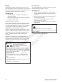
Important Safety Information
The manufacturer cannot possibly anticipate every possible
circumstance that might involve a hazard. The warnings in
this manual, and the tags and decals affixed to the unit are,
therefore, not all-inclusive. If you use a procedure, work
method or operating technique that the manufacturer does
not specifically recommend, you must satisfy yourself that it
is safe for you and others. You must also make sure that the
procedure, work method or operating technique that you
choose does not render the generator unsafe.
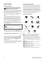
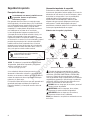
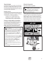
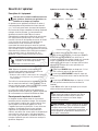
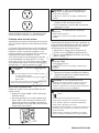
Safety Symbols and Meanings
The safety alert symbol indicates a potential personal
injury hazard. A signal word (DANGER, WARNING, or
CAUTION) is used with the alert symbol to designate a
degree or level of hazard seriousness. A safety symbol may
be used to represent the type of hazard. The signal word
NOTICE is used to address practices not related to personal
injury.
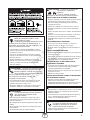
DANGER indicates a hazard which, if not avoided, will
result in death or serious injury.
WARNING indicates a hazard which, if not avoided,
could result in death or serious injury.
CAUTION indicates a hazard which, if not avoided, could
result in minor or moderate injury.
NOTICE address practices not related to personal injury.
4 BRIGGSandSTRATTON.COM
Fire
Explosion
Toxic Fumes
Hot Surface
Moving Parts
Electrical Shock
Kickback
Flying Objects
Operator’s Manual
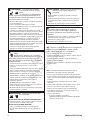
WARNING
Removing the neutral bond could result in
death, bodily injury and/or property damage.
• DO NOT remove the neutral bond.
Lift Point
Hand Crush
Not for
Reproduction

5
WARNING Running engine gives off carbon
monoxide, an odorless, colorless, poison gas.
Breathing carbon monoxide can cause headache,
fatigue, dizziness, vomiting, confusion, seizures,
nausea, fainting or death.
• Operate generator ONLY outdoors.
• Install a battery operated carbon monoxide alarm near the
bedrooms.
• Keep exhaust gas from entering a confined area through
windows, doors, ventilation intakes, or other openings.
• DO NOT start or run engine indoors or in an enclosed area,
(even if windows and doors are open), including the generator
compartment of a recreational vehicle (RV).
WARNING The engine exhaust from this product
contains chemicals known to the State of California to
cause cancer, birth defects, or other reproductive harm.
WARNING Certain components in this product and
related accessories contain chemicals known to the State
of California to cause cancer, birth defects or other
reproductive harm. Wash hands after handling.
WARNING Starter cord kickback (rapid retraction) can
result in bodily injury. Kickback will pull hand
and arm toward engine faster than you can let
go.
Broken bones, fractures, bruises, or sprains could result.
• When starting engine, pull cord slowly until resistance is felt
and then pull rapidly to avoid kickback.
• NEVER start or stop engine with electrical devices plugged in
and turned on.
WARNING
• This generator does not meet U. S. Coast Guard Regulation
33CFR-183 and should not be used on marine applications.
• Failure to use the appropriate U. S. Coast Guard approved
generator could result in death or serious injury and/or property
damage.
WARNING Fuel and its vapors are extremely
flammable and explosive.
Fire or explosion can cause severe
burns or death.
WHEN ADDING OR DRAINING FUEL
• Turn generator OFF and let it cool at least 2 minutes before
removing fuel cap. Loosen cap slowly to relieve pressure in
tank.
• Fill or drain fuel tank outdoors.
• DO NOT overfill tank. Allow space for fuel expansion.
• If fuel spills, wait until it evaporates before starting engine.
• Keep fuel away from sparks, open flames, pilot lights, heat, and
other ignition sources.
• DO NOT light a cigarette or smoke.
WHEN STARTING EQUIPMENT
• Ensure spark plug, muffler, fuel cap, and air cleaner are in
place.
• DO NOT crank engine with spark plug removed.
WHEN OPERATING EQUIPMENT
• DO NOT tip engine or equipment at angle which causes fuel to
spill.
• This generator is not for use in mobile equipment or marine
applications.
WHEN TRANSPORTING, MOVING OR REPAIRING EQUIPMENT
• Transport/move/repair with fuel tank EMPTY or with fuel shutoff
valve OFF.
• DO NOT tip engine or equipment at angle which causes fuel to
spill.
• Disconnect spark plug wire.
WHEN STORING FUEL OR EQUIPMENT WITH FUEL IN TANK
• Store away from furnaces, stoves, water heaters, clothes
dryers, or other appliances that have pilot light or other ignition
source because they can ignite fuel vapors.
WARNING Lifting Hazard.
Falling generator can result in death, bodily
injury, and/or property damage.
• Stand clear of generator. Center point lift is designed to carry
only the weight of the generator.
• DO NOT overload center point lift bracket.
• DO NOT lift from center point lift gusset.
• DO NOT lift from folding handle.
WARNING Crush Hazard.
Center point lift bracket can crush and cut
resulting in bodily injury.
• Keep hands clear of area between bracket and folding handle.
Not for
Reproduction

NOTICE
Exceeding generators wattage/amperage capacity
can damage generator and/or electrical devices connected to
it.
• DO NOT exceed the generator’s wattage/amperage capacity. See
Don’t Overload Generator in the Operation section.
• Start generator and let engine stabilize before connecting
electrical loads.
• Connect electrical loads in OFF position, then turn ON for
operation.
• Turn electrical loads OFF and disconnect from generator before
stopping generator.
NOTICE
Improper treatment of generator can damage it
and shorten its life.
• Use generator only for intended uses.
• If you have questions about intended use, ask dealer or contact
local service center.
• Operate generator only on level surfaces.
• DO NOT expose generator to excessive moisture, dust, dirt, or
corrosive vapors.
• DO NOT insert any objects through cooling slots.
• If connected devices overheat, turn them off and disconnect them
from generator.
• Shut off generator if:
-electrical output is lost;
-equipment sparks, smokes, or emits flames;
-unit vibrates excessively.
6 BRIGGSandSTRATTON.COM
WARNING
Generator produces hazardous voltage.
Failure to isolate generator from power utility
can result in death or injury to electric utility
workers due to backfeed of electrical energy.
• When using generator for backup power, notify utility company.
Use approved transfer equipment to isolate generator from
electric utility.
• Use a ground fault circuit interrupter (GFCI) in any damp or
highly conductive area, such as metal decking or steel work.
• DO NOT touch bare wires or receptacles.
• DO NOT use generator with electrical cords which are worn,
frayed, bare or otherwise damaged.
• DO NOT operate generator in the rain or wet weather.
• DO NOT handle generator or electrical cords while standing in
water, while barefoot, or while hands or feet are wet.
• DO NOT allow unqualified persons or children to operate or
service generator.
WARNING Contact with muffler area can result in
serious burns.
Exhaust heat/gases can ignite
combustibles, structures or damage
fuel tank causing a fire.
• DO NOT touch hot parts and AVOID hot exhaust gases.
• Allow equipment to cool before touching.
• Keep at least 5 feet (152 cm) of clearance on all sides of
generator including overhead.
• It is a violation of California Public Resource Code, Section
4442, to use or operate the engine on any forest-covered,
brush-covered, or grass-covered land unless the exhaust
system is equipped with a spark arrester, as defined in Section
4442, maintained in effective working order. Other states or
federal jurisdictions may have similar laws.
Contact the original equipment manufacturer, retailer, or dealer
to obtain a spark arrester designed for the exhaust system
installed on this engine.
• Replacement parts must be the same and installed in the same
position as the original parts.
WARNING Unintentional sparking can result in fire or
electric shock.
WHEN ADJUSTING OR MAKING REPAIRS TO YOUR GENERATOR
• Disconnect the spark plug wire from the spark plug and place
the wire where it cannot contact spark plug.
WHEN TESTING FOR ENGINE SPARK
• Use approved spark plug tester.
• DO NOT check for spark with spark plug removed.
WARNING Starter and other rotating parts can
entangle hands, hair, clothing, or accessories.
• NEVER operate generator without protective housing or covers.
• DO NOT wear loose clothing, jewelry or anything that may be
caught in the starter or other rotating parts.
• Tie up long hair and remove jewelry.
CAUTION
Excessively high operating speeds increase
risk of injury and damage to generator.
Excessively low speeds impose a heavy load.
• DO NOT tamper with governed speed. Generator supplies
correct rated frequency and voltage when running at governed
speed.
• DO NOT modify generator in any way.
Not for
Reproduction

Assembly
Your generator requires some assembly and is ready for use
after it has been properly serviced with the recommended oil
and fuel.
If you have any problems with the assembly of your generator,
please call the generator helpline at (800) 743-4115. If calling
for assistance, please have the model, revision, and serial
number from the identification label available. See Generator
Controls and Features for identification label location.
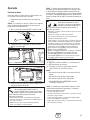
Unpack Generator
1. Set the carton on a rigid, flat surface.
2. Remove everything from carton except generator.
3. Open carton completely by cutting each corner from
top to bottom.
4. Leave generator on carton to install wheel kit.
Shipment Contents
The generator is supplied with:
• Engine oil bottles
• Operator’s manual
• Engine operator’s manual
• Wheel kit
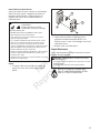
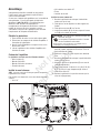
Install Wheel Kit
NOTICE Wheel kit is not intended for over-the-road use.
You will need the following tools to install these
components:
• 1/2” wrench
• Socket wrench with a 1/2” socket
• Pliers
• Safety glasses
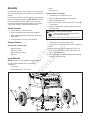
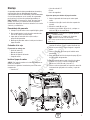
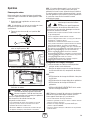
Install the wheel kit as follows:
1. Tip generator so that engine end is up.
2. Slide axle (A) through both mounting brackets.
3. Slide a wheel (B) over axle.
4. Place a washer (C) on axle and then place an e-ring (D)
in axle groove.
5. Install e-ring with pliers, squeezing from top of e-ring
to bottom of axle.
6. Repeat steps 3 through 5 to secure second wheel.
7. Tip generator so that engine side is down.
8. Line up holes in support leg (E) with holes in generator
frame.
9. Attach support leg using 4 carriage bolts (5/16-18 x
0.75) (F) and 4 lock hex nuts (G). Tighten with a 1/2”
wrench and socket wrench.
10. Return generator to normal operating position (resting
on wheels and support leg).
7
CAUTION
E-rings can cause eye injury.
E-rings can spring back and become airborne
when installing or removing.
• Always wear eye protection when installing/removing e-rings.
G
G
F
D
B
F
C
B
C
E
A
D
Not for
Reproduction

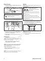
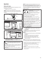
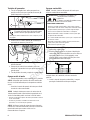
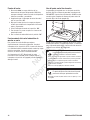
Moving Generator
1. Pull folding handle to the upright position until spring
pin (A) locks into place.
2. Place your foot onto the round bar (B) located under
the recoil starter and pull back on the handle.
3. Push or pull generator to desired location.
4. Place foot on round bar and gently let generator tip
forward to rest on support leg.
5. Pull on spring pin and push handle forward to fold
down handle.
Add Engine Oil
• Place generator on a level surface.
NOTICE Verify provided oil bottles are the correct viscosity
for current ambient temperature.
• Refer to engine operator’s manual and follow oil
recommendations and instructions.
NOTICE
Any attempt to crank or start the engine before it
has been properly filled with the recommended oil will
result in equipment failure.
• Refer to engine manual for oil information.
• Damage to equipment resulting from failure to follow this
instruction will void warranty.
NOTICE Check oil often during engine break–in. Refer to
engine operator’s manual for recommendations.
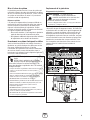
Add Fuel
NOTICE Refer to engine operator’s manual and follow fuel
recommendations.
1. Clean area around fuel fill cap, remove cap.
2. Slowly add unleaded gasoline to fuel tank. Be careful
not to overfill. Allow minimum 3/4” (2 cm) (C) from top
of strainer to avoid fuel spillage from cap.
NOTICE Occasionally clear the fuel strainer of any dirt, rust,
or other particulate matter.
3. Install fuel cap and let any spilled fuel evaporate before
starting engine.
WARNING Crush Hazard.
Center point lift bracket can crush and cut
resulting in bodily injury.
• Keep hands clear of area between bracket and folding handle.
A
8 BRIGGSandSTRATTON.COM
WARNING Fuel and its vapors are extremely
flammable and explosive.
Fire or explosion can cause severe
burns or death.
WHEN ADDING FUEL
• Turn generator OFF and let it cool at least 2 minutes before
removing fuel cap. Loosen cap slowly to relieve pressure in
tank.
• Fill fuel tank outdoors.
• DO NOT overfill tank. Allow space for fuel expansion.
• If fuel spills, wait until it evaporates before starting engine.
• Keep fuel away from sparks, open flames, pilot lights, heat, and
other ignition sources.
• DO NOT light a cigarette or smoke.
B
C
Not for
Reproduction

System Ground
The generator has a system ground that connects the
generator frame components to the ground terminals on the
AC output receptacles. The system ground is connected to
the AC neutral wire (the neutral is bonded to the generator
frame).
Special Requirements
There may be Federal or State Occupational Safety and
Health Administration (OSHA) regulations, local codes, or
ordinances that apply to the intended use of the generator.
Please consult a qualified electrician, electrical inspector, or
the local agency having jurisdiction:
• In some areas, generators are required to be registered
with local utility companies.
• If the generator is used at a construction site, there
may be additional regulations which must be observed.
Connecting to a Building’s Electrical System
Connections for standby power to a building’s electrical
system must be made by a qualified electrician. The
connection must isolate the generator power from utility
power or other alternative power sources and must comply
with all applicable laws and electrical codes.
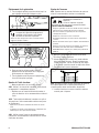
Generator Location
Clearances and Air Movement
Place generator outdoors in an area that will not accumulate
deadly exhaust gas. DO NOT place generator where exhaust
gas (A) could accumulate and enter inside or be drawn into
a potentially occupied building. Ensure exhaust gas is kept
away from any windows, doors, ventilation intakes, or other
openings that can allow exhaust gas to collect in a confined
area. Prevailing winds and air currents should be taken into
consideration when positioning generator.
A
9
WARNING
Generator produces hazardous voltage.
Failure to isolate generator from power utility
can result in death or injury to electric utility
workers due to backfeed of electrical energy.
• When using generator for backup power, notify utility company.
Use approved transfer equipment to isolate generator from
electric utility.
• Use a ground fault circuit interrupter (GFCI) in any damp or
highly conductive area, such as metal decking or steel work.
• DO NOT touch bare wires or receptacles.
• DO NOT use generator with electrical cords which are worn,
frayed, bare or otherwise damaged.
• DO NOT operate generator in the rain or wet weather.
• DO NOT handle generator or electrical cords while standing in
water, while barefoot, or while hands or feet are wet.
• DO NOT allow unqualified persons or children to operate or
service generator.
WARNING Exhaust heat/gases can ignite
combustibles, structures or damage fuel tank
causing a fire.
• Keep at least 5 ft. (152 cm) clearance on all sides of generator
including overhead.
Not for
Reproduction

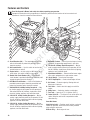
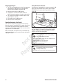
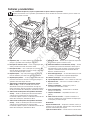
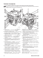
Features and Controls
Read this Operator’s Manual and safety rules before operating your generator.
Compare the illustrations with your generator, to familiarize yourself with the locations of various controls and
adjustments. Save this manual for future reference.
10 BRIGGSandSTRATTON.COM
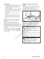
A - Circuit Breakers (AC) — The receptacles are provided
with circuit breakers to protect the generator against
electrical overload.
B - Idle Control Switch — Use this switch to turn the idle
control feature on and off.
C - Engine Switch — Set this switch to “On” before using
recoil starter. Set switch to “Off” to stop engine.
D - Double Pole Circuit Breaker (AC) — A double pole
circuit breaker is provided to protect the 120/240V, 30A
receptacle against electrical overload.
E - GFCI Main Circuit Breaker — A GFCI circuit breaker is
provided to protect against electrical ground fault and
protect the generator against electrical overload.
F - 120/240 Volt AC, 30 Amp Locking Receptacle — May
be used to supply electrical power for the operation of
120 and/or 240 Volt AC, 30 Amp, single phase, 60 Hz
electrical, lighting, appliance, tool and motor loads.
G - 120 Volt AC, 30 Amp Locking Receptacle — May be
used to supply electrical power for the operation of 120
Volt AC, 30 Amp, single phase, 60 Hz electrical lighting,
appliance, tool and motor loads.
H - 120 Volt AC, 20 Amp Locking Receptacle — May be
used to supply electrical power for the operation of 120
Volt AC, 20 Amp, single phase, 60 Hz electrical lighting,
appliance, tool and motor loads.
J - Grounding Fastener — Consult your local agency having
jurisdiction for grounding requirements in your area.
K - 120 Volt AC, 20 Amp, Duplex Receptacles — May be
used to supply electrical power for the operation of 120
Volt AC, 20 Amp, single phase, 60 Hz electrical, lighting,
appliance, tool, and motor loads.
L - Spark Arrester Muffler — Exhaust muffler lowers engine
noise and is equipped with a spark arrester screen.
M - Recoil Starter — Used to start the engine.
N - Oil Fill Cap/Dipstick — Check and add engine oil here.
P - Air Cleaner — Protects engine by filtering dust and
debris out of intake air.
R - Fuel Valve — Used to turn fuel supply on and off to
engine.
S - Choke Lever — Used when starting a cold engine.
T - Fuel Tank — Capacity of 7.5 U.S. gallons (28.4 L).
U - Center Point Lift — The lift point in the center of the unit
makes lifting the machine for transportation and/or
relocation easy.
Items Not Shown:
Identification Label — Provides model, revision, and serial
number of generator. Please have these readily available
when calling for assistance.
Oil Drain Plug — Drain engine oil here.
A
C
U
M
B
D
E
F
G
H
J
R
S
N
K
L
P
T
Not for
Reproduction

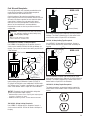
Cord Sets and Receptacles
Use only high quality, well-insulated, grounded extension
cords with the generator’s 120 Volt duplex receptacle.
Inspect extension cords before each use.
Check the ratings of all extension cords before you use
them. Extension cord sets used should be rated for 125 Volt
AC loads at 20 Amps or greater for most electrical devices.
Some devices, however, may not require this type of
extension cord. Check the operator’s manuals of those
devices for the manufacturer’s recommendations.
Keep extension cords as short as possible to minimize
voltage drop.
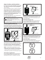
120/240 Volt AC, 30 Amp, Locking Receptacle
Use a NEMA L14-30 plug with this receptacle. Connect a
4-wire cord set rated for 250 Volt AC loads at 30 Amps (or
greater). You can use the same 4-wire cord if you plan to run
a 120 Volt load.
This receptacle powers 120/240 Volt AC, 60 Hz, single phase
loads requiring up to 6,500 watts of power (6.5 kW) at
27.0 Amps for 240 Volts or two independent 120 Volt loads
at 27.0 Amps each. The outlet is protected by a 2 pole rocker
switch circuit breaker and/or a 2 pole GFCI circuit breaker.
NOTICE
Receptacles may be marked with rating value
greater than generator output capacity.
• NEVER attempt to power a device requiring more amperage than
generator or receptacle can supply.
• DO NOT overload the generator. See Don’t Overload Generator.
120 Volt AC, 30 Amp Locking Receptacle
Use a NEMA L5–30 plug with this receptacle. Connect a
3–wire cord set rated for 125 Volt AC loads at 30 Amps to
the plug.
Use this receptacle to operate 120 Volt AC, 60 Hz, single
phase loads requiring up to 3,600 watts (3.6 kW) of power at
30 Amps. The outlet is protected by a 2 pole rocker switch
circuit breaker and/or a 2 pole GFCI circuit breaker.
120 Volt, 20 Amp Locking Type Receptacle
Use a NEMA L5–20 plug with this receptacle. Connect a
3–wire cord set rated for 125 Volt AC loads at 20 Amps to
the plug.
Use this receptacle to operate 120 Volt AC, 60 Hz, single
phase loads requiring up to 2,400 watts (2.4 kW) of power at
20 Amps. The outlet is protected by a rocker switch circuit
breaker and/or a 2 pole GFCI circuit breaker.
120 Volt AC, 20 Amp, Duplex Receptacles
The duplex receptacles are protected against overload by
rocker switch circuit breakers and/or a 2 pole GFCI circuit
breaker.
3-Wire Cord Set
Neutral
120V
Hot
Ground (Green)
NEMA L5-20
WARNING
Overloaded electrical cords can overheat,
arc, and burn resulting in death, bodily injury,
and/or property damage.
• ONLY use cords rated for your loads.
• Follow all safeties on electrical cords.
11
4-Wire Cord Set
240V
120V
120V
NEMA L14-30
W (Neutral)
X (Hot)
Y (Hot)
Ground (Green)
3-Wire Cord Set
Neutral
120V
Hot
Ground (Green)
NEMA L5-30
Not for
Reproduction

Use each receptacle to operate 120 Volt AC, single-phase,
60 Hz electrical loads requiring up to 2,400 watts (2.4 kW) at
20 Amps of current. Use cord sets that are rated for 125 Volt
AC loads at 20 Amps (or greater). Inspect cord sets before
each use.
Ground Fault Protection
This unit is equipped with a Ground Fault Circuit Interrupter
(GFCI). This device meets applicable federal, state and local
codes.
The GFCI protects against electrical shock that may be
caused if your body becomes a path which electricity travels
to reach ground. This could happen if you touch a “Live”
appliance or wire, or are touching plumbing or other
materials that connect to the ground.
When protected by a GFCI, one may still feel a shock, but the
GFCI should cut current off quickly enough so that a person
in normal health should not suffer any serious electrical
injury.
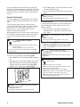
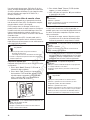
Test GFCI Circuit Breaker
Test your GFCI circuit breaker every month, as follows:
1. Press “Reset” button. The green power LED should be
on.
2. While generator is running, press “Test” button. The
green LED should turn off, the red LED should start
blinking, and the circuit breaker should trip to “Off”
position), which will disconnect power to outlets.
3. Press “Reset” button. The red LED should turn off and
the green LED should turn on.
4. Press circuit breaker to “On” position to restore circuit
power.
During Generator Use
If circuit breaker trips during use, it usually indicates faulty
electrical equipment or cords. However, test the circuit
breaker as follows;
1. Disconnect loads, reset and test circuit breaker as
described earlier. Let generator run without any loads
for 1 minute.
2. If circuit breaker tests correctly, the electrical
equipment or extension cords may be faulty. Replace
faulty electrical equipment and cords before further
use.
WARNING
Generator produces hazardous
voltage/current.
• DO NOT touch bare wires or receptacles.
• DO NOT use generator with electrical cords which are worn,
frayed, bare or otherwise damaged.
• DO NOT operate generator in the rain or wet weather.
• DO NOT handle generator or electrical cords while standing in
water, while barefoot, or while hands or feet are wet.
• DO NOT allow unqualified persons or children to operate or
service generator or electrical loads.
CAUTION
If circuit breaker trips in the 1 minute
period:
• DO NOT use generator.
• Call a Briggs & Stratton Power Products service center.
CAUTION
If circuit breaker tests correctly:
• Have qualified personnel check all electrical equipment and
cords for any defects.
• Replace electrical equipment and cords or take to a qualified
repair center.
12 BRIGGSandSTRATTON.COM
CAUTION
If sensing module LED’s do not change or
circuit breaker does not trip:
• DO NOT use generator.
• Call a Briggs & Stratton Power Products service center.
WARNING
WARNING
Generator produces hazardous
voltage/current.
• The GFCI will not protect you against the following situations:
-Line-to-line shocks;
-Current overloads or line-to-line short circuits.
• The fuse or circuit breaker at the control panel must provide
such protection.
CAUTION
If circuit breaker does not reset properly:
• DO NOT use generator.
• Call a Briggs & Stratton Power Products service center.
Not for
Reproduction

Operation
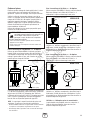
Starting the Engine
Disconnect all electrical loads from the generator. Use the
following start instructions:
1. Make sure unit is on a level surface.
NOTICE Failure to start and operate the unit on a level
surface will cause the unit not to start or shut down during
operation.
2. Turn the fuel valve (A) to the “On” position.
3. Make sure idle control switch is in “Off” position.
4. Push engine switch to “On” position.
5. Start engine according to instructions given in the
engine operator’s manual.
NOTICE If engine starts after 3 pulls but fails to run, or if
unit shuts down during operation, make sure unit is on a
level surface and check for proper oil level in crankcase. This
unit may be equipped with a low oil protection device. If so,
oil must be at proper level for engine to start. See engine
operator’s manual.
Connecting Electrical Loads
1. Let engine stabilize and warm up for a few minutes
after starting.
2. Plug in and turn on the desired 120 and/or 240 Volt
AC, single phase, 60 Hz electrical loads.
NOTICE
• DO NOT connect 240 Volt loads to the 120 Volt duplex
receptacles.
• DO NOT connect 3-phase loads to the generator.
• DO NOT connect 50 Hz loads to the generator.
• DO NOT OVERLOAD THE GENERATOR. See Don’t
Overload Generator.
NOTICE
Exceeding generators wattage/amperage capacity
can damage generator and/or electrical devices connected to
it.
• DO NOT exceed the generator’s wattage/amperage capacity. See
Don’t Overload Generator in the Operation section.
• Start generator and let engine stabilize before connecting
electrical loads.
• Connect electrical loads in OFF position, then turn ON for
operation.
• Turn electrical loads OFF and disconnect from generator before
stopping generator.
A
13
WARNING Contact with muffler area can result in
serious burns.
Exhaust heat/gases can ignite
combustibles, structures or damage
fuel tank causing a fire.
• DO NOT touch hot parts and AVOID hot exhaust gases.
• Allow equipment to cool before touching.
• Keep at least 5 feet (152 cm) of clearance on all sides of
generator including overhead.
• It is a violation of California Public Resource Code, Section
4442, to use or operate the engine on any forest-covered,
brush-covered, or grass-covered land unless the exhaust
system is equipped with a spark arrester, as defined in Section
4442, maintained in effective working order. Other states or
federal jurisdictions may have similar laws.
Contact the original equipment manufacturer, retailer, or dealer
to obtain a spark arrester designed for the exhaust system
installed on this engine.
• Replacement parts must be the same and installed in the same
position as the original parts.
WARNING Starter cord kickback (rapid retraction) can
result in bodily injury. Kickback will pull hand
and arm toward engine faster than you can let
go.
Broken bones, fractures, bruises, or sprains could result.
• When starting engine, pull cord slowly until resistance is felt
and then pull rapidly to avoid kickback.
• NEVER start or stop engine with electrical devices plugged in
and turned on.
Not for
Reproduction

14 BRIGGSandSTRATTON.COM
Stopping the Engine
1. Turn OFF and unplug all electrical loads from generator
panel receptacles. NEVER start or stop engine with
electrical devices plugged in and turned ON.
2. Move idle control switch to “Off” position.
3. Let engine run at no-load for several minutes to
stabilize internal temperatures of engine and generator.
4. Turn engine off according to instructions given in the
engine operator’s manual.
5. Push engine switch to “Off” position.
6. Move fuel valve to “Off” position.
Operating Automatic Idle Control
This feature is designed to greatly improve fuel economy.
When this switch is turned to AUTO, the engine will only run
at its normal high governed engine speed when electrical
loads are connected. When electrical loads are removed, the
engine will run at a reduced speed.
With the switch OFF, the engine will run at the normal high
engine speed. Always have the switch off when starting and
stopping the engine.
Using the Center Point Lift
Your generator is equipped with a single center point lift (A).
Always lift your generator from the center point lift ONLY.
NEVER lift from the center point lift gusset (B) or folding
handle (C).
When lifting the generator, make sure no additional weight
has been added or is hanging from the generator. Adding
weight to the generator can cause damage to the center
point lift causing an unsafe condition.
C
A
B
WARNING Lifting Hazard.
Falling generator can result in death, bodily
injury, and/or property damage.
• Stand clear of generator. Center point lift is designed to carry
only the weight of the generator.
• DO NOT overload center point lift bracket.
• DO NOT lift from center point lift gusset.
• DO NOT lift from folding handle.
WARNING Crush Hazard.
Center point lift bracket can crush and cut
resulting in bodily injury.
• Keep hands clear of area between bracket and folding handle.
Not for
Reproduction

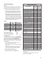
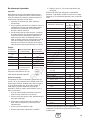
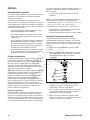
Don’t Overload Generator
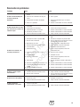
Capacity
You must make sure your generator can supply enough
rated (running) and surge (starting) watts for the items you
will power at the same time. Follow these simple steps:
1. Select the items you will power at the same time.
2. Total the rated (running) watts of these items. This is
the amount of power your generator must produce to
keep your items running. See the table on the right.
3. Estimate how many surge (starting) watts you will need.
Surge wattage is the short burst of power needed to
start electric motor-driven tools or appliances such as a
circular saw or refrigerator. Because not all motors start
at the same time, total surge watts can be estimated by
adding only the item(s) with the highest additional surge
watts to the total rated watts from step 2.
Example:
Total Rated (Running) Watts = 3275
Highest Additional Surge Watts = 2350
Total Generator Output Required = 5625
Power Management
To prolong the life of your generator and attached devices, it
is important to take care when adding electrical loads to your
generator. There should be nothing connected to the
generator outlets before starting its engine. The correct and
safe way to manage generator power is to sequentially add
loads as follows:
1. With nothing connected to the generator, start the
engine as described in this manual.
2. Plug in and turn on the first load, preferably the largest
load you have.
3. Permit the generator output to stabilize (engine runs
smoothly and attached device operates properly).
4. Plug in and turn on the next load.
5. Again, permit the generator to stabilize.
6. Repeat steps 4 and 5 for each additional load.
NEVER add more loads than the generator capacity. Take
special care to consider surge loads in generator capacity, as
described above.
* Wattages listed are approximate only. Check tool or
appliance for actual wattage.
15
Tool or Appliance
Running (Rated)
Watts
Additional Starting
(Surge) Watts
Water Well Pump 1200 2100
Refrigerator 700 2200
Furnace Fan 800 2350
Television 500 —
Light (75 Watts) 75 —
3275 Total
Running Watts
2350 Highest
Starting Watts
Wattage Reference Guide
Tool or Appliance
Running*
(Rated)
Watts
Additional
Starting
(Surge)
Watts
Essentials
Light Bulb - 75 watt 75 —
Furnace Fan Blower - 1/2 HP 800 2350
Sump Pump - 1/3 HP 800 1300
Refrigerator/Freezer 700 2200
Water Well Pump - 1/2 HP 1000 2100
Heating/Cooling
Window AC - 10,000 BTU 1200 3600
Humidifier - 13 Gal 175 —
Central AC - 24,000 BTU 3800 11400
Kitchen
Microwave Oven - 1000 Watt 1000 —
Coffee Maker 1000 —
Electric Stove - 8” Element 2100 —
Toaster 850 —
Family Room
DVD/CD Player 100 —
VCR 100 —
Stereo Receiver 450 —
Color Television - 27 in 500 —
Personal Computer w/17 in
monitor
800 —
Other
Security System 500 —
AM/FM Clock Radio 100 —
Garage Door Opener - 1/2 HP 875 2350
Electric Water Heater 4700 11700
DIY/Job Site
Quartz Halogen Work Light 1000 —
Airless Sprayer - 1/3 HP 600 1200
Reciprocating Saw 960 —
Electric Drill - 1/2 HP, 5.4 Amps 600 900
Circular Saw - 7-1/4 in 1400 2300
Miter Saw - 10 in 1800 1800
Table Planer - 6 in 1800 1800
Table Saw/Radial Arm Saw - 10 in 2000 2000
Air Compressor - 1 HP 1600 4500
Not for
Reproduction

Maintenance
General Recommendations
Regular maintenance will improve the performance and
extend the life of the generator. See an authorized dealer for
service.
The generator’s warranty does not cover items that have
been subjected to operator abuse or negligence. To receive
full value from the warranty, the operator must maintain the
generator as instructed in this manual and the engine
operator’s manual.
• Some adjustments will need to be made periodically to
properly maintain your generator.
• All maintenance in this manual and the engine
operator’s manual should be made at least once each
season.
• Once a year you should clean or replace the spark plug,
clean or replace the air filter. A new spark plug and
clean air filter assure proper fuel-air mixture and help
your engine run better and last longer. Please refer to
your engine operator’s manual for more details.
Generator Maintenance
Generator maintenance consists of keeping the unit clean
and dry. Operate and store the unit in a clean dry
environment where it will not be exposed to excessive dust,
dirt, moisture, or any corrosive vapors. Cooling air slots in
the generator must not become clogged with snow, leaves,
or any other foreign material.
NOTICE DO NOT use water or other liquids to clean
generator. Liquids can enter engine fuel system, causing
poor performance and/or failure to occur. In addition, if
liquid enters generator through cooling air slots, some of the
liquid will be retained in voids and cracks of the rotor and
stator winding insulation. Liquid and dirt buildup on the
generator internal windings will eventually decrease the
insulation resistance of these windings.
Cleaning
Daily or before use, look around and underneath the
generator for signs of oil or fuel leaks. Clean accumulated
debris from inside and outside the generator. Keep the
linkage, spring and other engine controls clean. Keep the
area around and behind the muffler free from any
combustible debris. Inspect cooling air slots and openings
on generator. These openings must be kept clean and
unobstructed.
Engine parts should be kept clean to reduce the risk of
overheating and ignition of accumulated debris:
• Use a damp cloth to wipe exterior surfaces clean.
NOTICE
Improper treatment of generator can damage it
and shorten its life.
• DO NOT expose generator to excessive moisture, dust, dirt, or
corrosive vapors.
• DO NOT insert any objects through cooling slots.
• Use a soft bristle brush to loosen caked on dirt or oil.
• Use a vacuum cleaner to pick up loose dirt and debris.
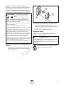
Fuel Valve Maintenance
The fuel valve is equipped with a fuel sediment cup, screen,
retaining ring and o-ring that need to be cleaned every 100
hours or once a year (whichever occurs first).
1. Move fuel valve to “Off” position.
2. Remove sediment cup (A) from fuel valve. Remove
o-ring (B), retaining ring (C) and screen (D) from fuel
valve.
3. Wash sediment cup, o-ring, retaining ring, and screen
in a nonflammable solvent. Dry them thoroughly.
4. Place screen, retaining ring, and o-ring into fuel valve.
Install sediment cup and tighten securely.
5. Move fuel valve to “On” position, and check for leaks.
Replace o-ring if there is any leakage.
16 BRIGGSandSTRATTON.COM
A
B
C
D
Not for
Reproduction

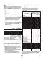
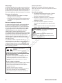
Inspect Muffler and Spark Arrester
Inspect the muffler for cracks, corrosion, or other damage.
Remove the spark arrester, if equipped, and inspect for
damage or carbon blockage. If replacement parts are
required, make sure to use only original equipment
replacement parts.
Clean and inspect the spark arrester every 100 hours as
follows:
1. To remove muffler heat shield (A) from muffler (B),
remove four screws that connect guard to muffler
bracket.
2. Remove four screws that attach spark arrester screen (C).
3. Inspect screen and obtain a replacement if torn,
perforated or otherwise damaged. DO NOT use a
defective screen. If screen is not damaged, clean it with
commercial solvent.
4. Reattach screen and muffler guard.
Engine Maintenance
See the engine operator’s manual for instructions on how to
properly maintain the engine.
KEEP OUT OF REACH OF CHILDREN. DON’T
POLLUTE. CONSERVE RESOURCES. RETURN
USED OIL TO COLLECTION CENTERS.
17
A
B
C
WARNING Contact with muffler area can result in
serious burns.
Exhaust heat/gases can ignite
combustibles, structures or damage
fuel tank causing a fire.
• DO NOT touch hot parts and AVOID hot exhaust gases.
• Allow equipment to cool before touching.
• Keep at least 5 feet (152 cm) of clearance on all sides of
generator including overhead.
• It is a violation of California Public Resource Code, Section
4442, to use or operate the engine on any forest-covered,
brush-covered, or grass-covered land unless the exhaust
system is equipped with a spark arrester, as defined in Section
4442, maintained in effective working order. Other states or
federal jurisdictions may have similar laws.
Contact the original equipment manufacturer, retailer, or dealer
to obtain a spark arrester designed for the exhaust system
installed on this engine.
• Replacement parts must be the same and installed in the same
position as the original parts.
CAUTION Avoid prolonged or repeated skin contact
with used motor oil.
• Used motor oil has been shown to cause skin cancer in certain
laboratory animals.
• Thoroughly wash exposed areas with soap and water.
Not for
Reproduction

Storage
The generator should be started at least once every seven
days and allowed to run at least 30 minutes. If this cannot be
done and you must store the unit for more than 30 days, use
the following guidelines to prepare it for storage.
Generator Storage
• Clean the generator as outlined in Cleaning in the
Maintenance section.
• Check that cooling air slots and openings on generator
are open and unobstructed.
Long Term Storage Instructions
Fuel can become stale when stored over 30 days. Stale fuel
causes acid and gum deposits to form in the fuel system or
on essential carburetor parts. To keep fuel fresh, use Briggs
& Stratton FRESH START® fuel stabilizer, available as a
liquid additive or a drip concentrate cartridge.
There is no need to drain gasoline from the engine if a fuel
stabilizer is added according to instructions. Run the engine
for 2 minutes to circulate the stabilizer throughout the fuel
system. The engine and fuel can then be stored up to
24 months.
If gasoline in the engine has not been treated with a fuel
stabilizer, it must be drained into an approved container. Run
the engine until it stops from lack of fuel. The use of a fuel
stabilizer in the storage container is recommended to
maintain freshness.
Storing the Engine
See the engine operator’s manual for instructions on how to
properly prepare the engine for storage.
Other Storage Tips
1. DO NOT store fuel from one season to another unless it
has been treated as described in Long Term Storage
Instructions.
2. Replace fuel can if it starts to rust. Contaminated fuel
will cause engine problems.
3. If possible, store unit indoors and cover it to give
protection from dust and dirt.
4. Cover unit with a suitable protective cover that does not
retain moisture.
5. Store generator in clean, dry area.
18 BRIGGSandSTRATTON.COM
WARNING Fuel and its vapors are extremely
flammable and explosive.
Fire or explosion can cause severe
burns or death.
WHEN STORING FUEL OR EQUIPMENT WITH FUEL IN TANK
• Store away from furnaces, stoves, water heaters, clothes dryers
or other appliances that have pilot light or other ignition source
because they can ignite fuel vapors.
WHEN DRAINING FUEL
• Turn generator OFF and let it cool at least 2 minutes before
removing fuel cap. Loosen cap slowly to relieve pressure in
tank.
• Drain fuel tank outdoors.
• Keep fuel away from sparks, open flames, pilot lights, heat, and
other ignition sources.
• DO NOT light a cigarette or smoke.
WARNING
Storage covers can be flammable.
• DO NOT place a storage cover over a hot generator.
• Let equipment cool for a sufficient time before placing the cover
on the equipment.
Not for
Reproduction

19
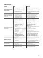
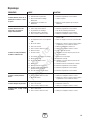
Troubleshooting
Problem Cause Correction
Engine is running, but no AC
output is available.
1. One of the circuit breakers is open.
2. Fault in generator.
3. Poor connection or defective cord set.
4. Connected device is bad.
1. Reset circuit breaker.
2. Contact authorized service facility.
3. Check and repair.
4. Connect another device that is in good
condition.
Engine runs good at no-load
but "bogs down" when loads
are connected.
1. Short circuit in a connected load.
2. Engine speed is too slow.
3. Generator is overloaded.
4. Shorted generator circuit.
5. Clogged or dirty fuel filter.
1. Disconnect shorted electrical load.
2. Contact authorized service facility.
3. See Don't Overload Generator.
4. Contact authorized service facility.
5. Clean or replace fuel filter.
Engine will not start; or starts
and runs rough.
1. Engine switch in "Off" position.
2. Fuel valve is in "Off" position.
3. Low oil level.
4. Dirty air cleaner.
5. Clogged or dirty fuel filter.
6. Out of fuel.
7. Stale fuel.
8. Spark plug wire not connected to spark
plug.
9. Bad spark plug.
10. Water in fuel.
11. Flooded.
12. Excessively rich fuel mixture.
13. Intake valve stuck open or closed.
14. Engine has lost compression.
1. Set switch to "On" position.
2. Turn fuel valve to "On" position.
3. Fill crankcase to proper level or place
generator on level surface.
4. Clean or replace air cleaner.
5. Clean or replace fuel filter.
6. Fill fuel tank.
7. Drain fuel tank and carburetor; fill with
fresh fuel.
8. Connect wire to spark plug.
9. Replace spark plug.
10. Drain fuel tank and carburetor; fill with
fresh fuel.
11. Wait 5 minutes and re-crank engine.
12. Contact authorized service facility.
13. Contact authorized service facility.
14. Contact authorized service facility.
Engine shuts down when
running.
1. Out of fuel.
2. Clogged or dirty fuel filter.
3. Low oil level.
1. Fill fuel tank.
2. Clean or replace fuel filter.
3. Fill crankcase to proper level or place
generator on level surface.
Engine lacks power.
1. Load is too high.
2. Dirty air filter.
3. Clogged or dirty fuel filter.
1. See Don't Overload Generator.
2. Replace air filter.
3. Clean or replace fuel filter.
Engine "hunts" or falters.
1. Carburetor is running too rich or too lean.
2. Clogged or dirty fuel filter.
1. Contact authorized service facility.
2. Clean or replace fuel filter.
Not for
Reproduction

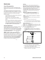
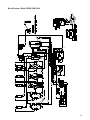
20 BRIGGSandSTRATTON.COM
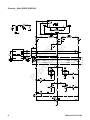
Schematic - Model 030488 (5500 Watt)
Not for
Reproduction
La page est en cours de chargement...
La page est en cours de chargement...
La page est en cours de chargement...
La page est en cours de chargement...
La page est en cours de chargement...
La page est en cours de chargement...
La page est en cours de chargement...
La page est en cours de chargement...
La page est en cours de chargement...
La page est en cours de chargement...
La page est en cours de chargement...
La page est en cours de chargement...
La page est en cours de chargement...
La page est en cours de chargement...
La page est en cours de chargement...
La page est en cours de chargement...
La page est en cours de chargement...
La page est en cours de chargement...
La page est en cours de chargement...
La page est en cours de chargement...
La page est en cours de chargement...
La page est en cours de chargement...
La page est en cours de chargement...
La page est en cours de chargement...
La page est en cours de chargement...
La page est en cours de chargement...
La page est en cours de chargement...
La page est en cours de chargement...
La page est en cours de chargement...
La page est en cours de chargement...
La page est en cours de chargement...
La page est en cours de chargement...
La page est en cours de chargement...
La page est en cours de chargement...
La page est en cours de chargement...
La page est en cours de chargement...
La page est en cours de chargement...
La page est en cours de chargement...
La page est en cours de chargement...
La page est en cours de chargement...
La page est en cours de chargement...
La page est en cours de chargement...
La page est en cours de chargement...
La page est en cours de chargement...
La page est en cours de chargement...
La page est en cours de chargement...
La page est en cours de chargement...
La page est en cours de chargement...
La page est en cours de chargement...
La page est en cours de chargement...
La page est en cours de chargement...
La page est en cours de chargement...
-
 1
1
-
 2
2
-
 3
3
-
 4
4
-
 5
5
-
 6
6
-
 7
7
-
 8
8
-
 9
9
-
 10
10
-
 11
11
-
 12
12
-
 13
13
-
 14
14
-
 15
15
-
 16
16
-
 17
17
-
 18
18
-
 19
19
-
 20
20
-
 21
21
-
 22
22
-
 23
23
-
 24
24
-
 25
25
-
 26
26
-
 27
27
-
 28
28
-
 29
29
-
 30
30
-
 31
31
-
 32
32
-
 33
33
-
 34
34
-
 35
35
-
 36
36
-
 37
37
-
 38
38
-
 39
39
-
 40
40
-
 41
41
-
 42
42
-
 43
43
-
 44
44
-
 45
45
-
 46
46
-
 47
47
-
 48
48
-
 49
49
-
 50
50
-
 51
51
-
 52
52
-
 53
53
-
 54
54
-
 55
55
-
 56
56
-
 57
57
-
 58
58
-
 59
59
-
 60
60
-
 61
61
-
 62
62
-
 63
63
-
 64
64
-
 65
65
-
 66
66
-
 67
67
-
 68
68
-
 69
69
-
 70
70
-
 71
71
-
 72
72


Simplicity 030488-0 Manuel utilisateur
- Catégorie
- Groupes électrogènes
- Taper
- Manuel utilisateur
- Ce manuel convient également à
dans d''autres langues
- English: Simplicity 030488-0 User manual
- español: Simplicity 030488-0 Manual de usuario
Documents connexes
-
Simplicity 030487-0 Manuel utilisateur
-
-
-
Briggs & Stratton OPERATOR'S/WDS MANUAL BRIGGS & STRATTON PRO4000 GENERATOR MODEL- 030335-0 Manuel utilisateur
-
-
-
-
Briggs & Stratton 030206 Manuel utilisateur
-
-