Epson BrightLink 475Wi Guide d'installation
- Catégorie
- Projecteurs de données
- Taper
- Guide d'installation

Installation Guide
Guide d’installation

2
Safety Instructions
For your safety, read all the instructions in this guide before using the wall mount. Incorrect handling that
ignores instructions in this guide could damage the wall mount or could result in personal injury or property
damage. Keep this installation guide on hand for future reference.
Read the safety instructions in the User's Guide for your projector and follow the instructions in this document.
Explanation of Symbols
The warning marks shown below are used throughout this installation guide to prevent personal injury or
property damage. Make sure you understand these warnings when reading this installation guide.
Safety Precautions for Installation
This symbol indicates information that, if ignored, could possibly result in personal injury or even death
due to incorrect handling.
This symbol indicates information that, if ignored, could possibly result in personal injury or physical
damage due to incorrect handling.
This symbol indicates related or useful information.
Symbol indicating an action that must not be done
Symbol indicating an action that should be done
The wall mount is designed specifically for mounting a projector to a wall. If anything other than a
projector is mounted, the weight may result in damage.
If the wall mount falls, it could cause personal injury or property damage.
The installation work (wall mounting) should be performed by specialists who have technical knowledge
and ability. Incomplete or incorrect installation could cause the wall mount to fall and cause personal
injury or property damage.
Follow the instructions in this guide when installing the wall mount.
If the instructions are not followed, the wall mount may fall, resulting in personal injury or property damage.
Handle the power cord carefully.
Incorrect handling may cause fire or electric shock. Observe the following precautions when handling:
• Do not handle the power plug with wet hands.
• Do not use a power cord that is damaged or modified.
• Do not pull the power cord with too much force when routing the cable through the wall mount.
Do not install the wall mount in a place where it might be subjected to vibration or shock.
Vibration or shock could cause damage to the projector or mounting surface. It could also cause the wall mount or
projector to fall and cause personal injury or property damage.
Install the wall mount so that it can sufficiently support the weight of the projector and wall mount, and
resist any horizontal vibration. Use M8 nuts and bolts.
Nuts and bolts smaller than M8 could cause the wall mount to fall. Epson accepts no responsibility for any damage
or injury caused by lack of wall strength or inadequate installation.
The installation work should be performed by at least two qualified service personnel. If you need to
loosen any screws during installation, be careful not to drop the wall mount.
If the wall mount or projector falls, it could cause personal injury or property damage.
Warning
Caution
Warning

3
English
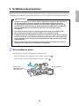
Location
• Before installing the projector, verify the power supply wiring for the installation location.
• Install the projector away from other electric devices such as fluorescent lights or air conditioners. Some
kinds of fluorescent lights could interfere with the remote control of the projector.
• Install the projector away from direct sunlight and other bright light sources.
• It is recommended to keep the VGA computer cable length less than 65 ft (20 meters) to reduce external
noise.
About This Installation Guide
This guide describes how to mount the ultra-short-throw projectors BrightLink Pro 1410Wi, BrightLink 475Wi/
480i/485Wi, and PowerLite 470/475W/480/485W to a wall using the included EPSON wall mount.
When you mount the projector on the wall with the wall mount, the wall requires enough strength to hold
the projector and the wall mount.
This wall mount should be installed on a concrete wall. Confirm the weight of the projector and the wall
mount before installation, and maintain the strength of the wall. If the wall is not strong enough, reinforce
the wall before installation.
Inspect the wall mount on a regular basis to ensure there are no broken parts or loose screws.
If there are any broken parts, stop using the wall mount immediately. If the wall mount or projector falls, it could
cause personal injury or property damage.
Never modify the wall mount.
Do not hang on the wall mount or hang a heavy object on the wall mount.
If the projector or wall mount falls, it could cause personal injury or property damage.
Do not use adhesives, lubricants, or oils to install or adjust the wall mount. If you use adhesives to prevent the
screws from loosening or things such as lubricants or oils on the part of the projector attached to the slide plate,
the case may crack and cause the projector to fall, resulting in personal injury or property damage.
Tighten all screws firmly after adjustment.
Otherwise, the projector or wall mount may fall and cause personal injury or property damage.
Never loosen the bolts and nuts after installation.
Confirm that the screws have not become loose on a regular basis. If you find any loose screws, tighten them
firmly. Otherwise, the projector or wall mount may fall and cause personal injury or property damage.
When performing wiring, make sure the cable does not come into contact with any screws or bolts.
Handling the cable incorrectly may cause fire or electric shock.
Do not install the wall mount in a location where the operating temperature for your projector model may
be exceeded. Such an environment may damage the projector.
Install the wall mount in a place free from excessive dust and humidity to prevent the lens or optical
components from becoming dirty.
Do not use excessive force when adjusting the wall mount.
The wall mount may break, resulting in personal injury.
Warning
Caution

4
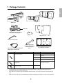
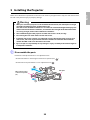
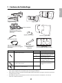
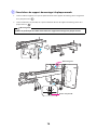
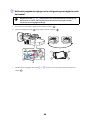
1 Package Contents
s5
2 Specifications
s6
3 Connecting Devices
s8
4 Positioning the Projector
1. Installation worksheet for projecting on a pre-installed wall-mounted board
2. Installation worksheet for projecting on a plain wall
3. Installation measurements in inches
4. Installation measurements in millimeters
s11
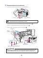
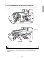
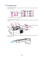
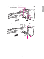
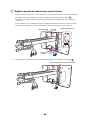
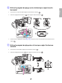
5 Installing the Projector
1. Disassemble the parts
2. Assemble the parts
3. Install the wall plate on the wall
4. Determine the projection distance and pull out the slider
5. Route the cables through the wall mount arm
6. Attach the mount arm to the wall plate
7. Adjust the vertical slide position of the arm
8. Attach the projector to the wall mount
9. Connect the power cord and other cables to the projector
s25
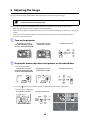
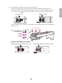
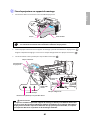
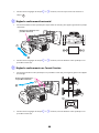
6 Adjusting the Image
1. Turn on the projector
2. Display the mount adjustment test pattern, as described below
3. Change the aspect ratio if necessary
4. Adjust the focus
5. Use the adjustment knob on the left side to adjust the horizontal roll
6. Use the adjustment knob on the right side to adjust the horizontal rotation
7. Use the adjustment knob on the top to adjust the vertical tilt
8. Adjust the horizontal slide
9. Adjust the forward/backward slide
10. Adjust the vertical slide
11. Turn off the display of the test pattern
s36
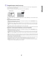
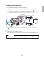
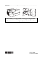
7 Attaching the Covers
1. Attach the wall plate covers and end cap
2. Attach the cable cover to the projector
s42

5
English
1 Package Contents
• Use the bolts or screws supplied with the wall mount to install it as directed in this guide. Do not
substitute these bolts with any other types.
• You need to use commercially available M8 x 50 mm anchors (at least 3) to attach the wall plate to the
wall.
• Gather the tools and parts you need before you begin installation, including a #3 cross-head screwdriver.
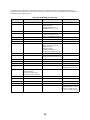
Shape Name Quantity Application
M4 x 12 mm hexagon socket head cap bolt with
washer/spring washer
6 For wall plate assembly
4 For 3-axis adjustment unit/wall mount
installation
4 For slide plate/projector installation
2 For slide plate/3-axis adjustment unit
installation (secured when shipped)
M6 x 20 mm hexagon shoulder bolt with washer/
spring washer
1 For wall mount/wall plate installation
(secured when shipped)
M6 x 20 mm cross recessed head shoulder screw
with plastic washer
3
Hexagon wrench (for M4)
Wall plate cover
Wall mount
Template sheet
(for installing the wall plate)
End cap
3-axis adjustment unit (attached
to slide plate when shipped)
Open-ended wrench
13 mm (for M8 and M6) x
6 mm (for hexagonal
shaft)
Wall plate
VGA computer cable (may be included
with projector or wall mount)
Slide plate

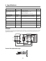
6
2 Specifications
Wall plate
The wall plate is in three piece when shipped, and the middle piece is attached to the wall mount arm. Use the
included M4 x 12 mm bolts (x6) to attach the separate pieces together before mounting the projector. See
page 26 for instructions.
Vertical slide adjustment range
Item Specification Additional information Reference
Page
Wall mount weight (including the
3-axis adjustment unit, slide plate,
wall plate, wall plate cover, and
end cap)
Approx. 16.3 lb
(7.4 kg)
Wall mount: 6.2 lb (2.8 kg)
3-axis adjustment unit: 2.4 lb (1.1 kg)
Slide plate: 1.5 lb (0.7 kg)
Wall plate: 5.5 lb (2.5 kg)
Wall plate cover and end cap: 0.7 lb (0.3 kg)
—
Maximum load capacity 15.4 lb (7 kg) — —
Forward/backward slide
adjustment range
0 to 12.2 in.
(310 mm)
Arm slide adjustment range: 0 to 9.8 in. (248 mm)
Adjustment from 3-axis adjustment unit installation
position: 2.4 in. (62 mm)
Refer to the
illustration
below
Vertical slide adjustment range ± 1.5 in. (38 mm) — Refer to the
illustration
below
Horizontal roll adjustment range ± 3° Fine adjustments possible with adjustment knob
38
Horizontal rotation adjustment
range
± 3° Fine adjustments possible with adjustment knob
39
Vertical tilt adjustment range ± 3° Fine adjustments possible with adjustment knob
39
Horizontal slide adjustment range ± 1.8 in. (45 mm) — Refer to the
illustration
below
4.7 in.
(120 mm)
1.2 in.
(30 mm)
1.3 in.
(33 mm)
2.9 in.
(75 mm)
4.2 in.
(106.5 mm)
3.1 in.
(79 mm)
1.6 in.
(40 mm)
4.4 in.
(112 mm)
8.0 in. (203 mm)
6.3 in. (160 mm)
8.4 in. (213 mm)
18 in. (456 mm)
8.7 in. (222 mm)
9.7 in. (246 mm)
1.5 in. (38 mm)
1.5 in. (38 mm)

7
English
Horizontal slide adjustment range
Forward/backward slide adjustment range
Arm slide adjustment range
Adjustment from 3-axis adjustment unit installation position
By changing the installation position of the 3-axis adjustment unit to the front or back, you can adjust the
installation position of the projector.
When the screen size is less than 70 inches, install it at the position marked with a stamp on the mount arm.
When the screen size is 70 inches or more, install it at the position marked with a stamp on the mount
arm.
To see these stamps, you need to remove the two top screws and slide out the arm extension.
1.8 in. (45 mm)
1.8 in. (45 mm)
9.8 in. (248 mm)
2.4 in.
(62 mm)
stamp
stamp

8
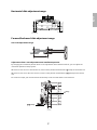
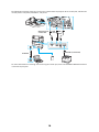
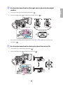
3Connecting Devices
Make sure you have the power cord, computer cable, and other parts at the location where the wall mount is
to be installed.
Make sure you also have all necessary cables for devices, such as a document camera or microphone, that you
will connect to the projector. For details, refer to the User’s Guide on the projector CD or at epson.com/
brightlinkdownloads (U.S.) or epson.ca/brightlinkdownloads (Canada).
Some of the illustrations in this guide may look different from your projector, but the
instructions are the same.
External speakers
LAN device
Microphone
USB cable
(for Interactive Functions on BrightLink
and BrightLink Pro models)
Document camera
(EPSON DC-06)
Power cord
Computer cable
(for computer video output)
Dedicated USB cable
(supplied with
document camera)
Audio cable
(not included)
LAN cable
(not included)
When interacting with a computer, you need a USB cable (unless you are connecting wirelessly to
the BrightLink Pro 1410Wi). When using the projector's built-in tools, you do not need a USB cable.
For Interactive Use (BrightLink 475Wi/480i/485Wi and BrightLink Pro 1410Wi)

9
English
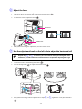
Connecting the Control Pad (BrightLink Pro 1410Wi Only)
The control pad is included with the BrightLink Pro 1410Wi projector. It provides a convenient alternative to
the remote control for turning on the projector, changing the source, and selecting whiteboard mode. You can
also use the control pad to capture, print, and save your projected images.
You must install the control pad on the same surface as the projector, within the range shown in the shaded
area below. You can use the included batteries to power the control pad, or the optional remote control cable
set (ELPKC28).
Remove the top cover and install the batteries. (If you have the optional remote control cable set, you do not
need batteries.)
68.9 in.
(1.75 m)
35.4 in.
(0.9 m)
27.6 in.
(0.7 m)
13.8 in.
(0.35 m)
9.8 in.
(0.25 m)
39.3 in. (1.0 m)
59.0 in. (1.5 m)
78.7 in. (2.0 m)
78.7 in.
(2.0 m)
60-inch
image
100-inch
image
Remote control
light emitting areas

10
The following illustration shows the connections available from the projector to the control pad, and from the
control pad to a computer, thumbdrive, and printer.
For more information on installing and connecting the control pad, see the Control Pad Installation Guide that
came with the projector.
Optional remote
control cable
USB
cable
USB cable (not included)
USB cable
USB
cable

11
English
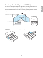
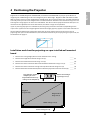
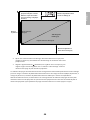
4 Positioning the Projector
BrightLink Pro 1410Wi, BrightLink 475Wi/485Wi, and PowerLite 475W/485W can project up to 100 inches
diagonally for a WXGA image or 88 inches diagonally for an XGA image. BrightLink 480i and PowerLite 470/
480 can project up to 93 inches diagonally for an XGA image. You can project onto a pre-installed whiteboard
or directly onto a plain wall. The height of the included wall mount determines the maximum image size and
how high the image appears on the wall or whiteboard. The distance of the projector from the wall (once it is
mounted on the adjustable arm of the wall mount) also affects image size and position.
If you are planning to project on a whiteboard, the image may not fill the entire board, depending on the
aspect ratio. If you match the image height to the board’s height, gaps may appear on the sides of the board.
Use the following worksheets to determine the proper location of the wall plate on the wall. If you are
projecting onto a pre-installed whiteboard, use the worksheet below. If you are projecting on a plain wall, use
the worksheet on page 12.
Installation worksheet for projecting on a pre-installed wall-mounted
board
1. Measure the ceiling height (distance from the floor to the ceiling) _____
2. Measure the height of the board’s image area (h). _____ (h)
3. Measure the width of the board’s image area (w). _____ (w)
4. Measure the distance from the floor to the bottom of the board’s image area (f). _____ (f)
5. Measure the distance from the ceiling to the top of the board’s image area (d). _____ (d)
6. Measure the thickness of the board (distance from the projection surface to the wall) (x). _____ (x)
10 in. (254 mm)—height of
wall plate plus cover
Required distance from top
of image area to wall plate (c)
Diagonal size of
image area (S)
Height of
image area (h)
Distance from ceiling to
top of image area (d)
Width of image area (w)
Distance from floor to
bottom of image area (f)

12
Installation worksheet for projecting on a plain wall
7. Determine the aspect ratio of the board or of the images that will be projected. For
new computers or laptops, this will most likely be WXGA (16:10). For older
equipment, this will most likely be XGA (4:3). You may need to consult your IT director
for this information.
___ 4:3 XGA ___ 16:10 WXGA ___ 16:9 Widescreen
8. Using the tables on pages 16 to 23 for your aspect ratio and desired image height (h),
find the required distance between the top of the image area and the wall plate (c). _____ (c)
9. Determine the position for your projector installation by adding the values for (f), (h),
and (c), plus an additional 10 inches for the height of the wall plate plus the cover.
If the ceiling height of your room (as noted in step 1) does not meet the minimum
ceiling height required for your board, you may need to select a smaller image size or
move the board to a lower position on the wall.
_____ (f)
_____ (h)
_____ (c)
+10
inches
_____ total
10. After confirming your image size, use tape or a pencil to mark the distance (c) from
the top of the image area on the board to the bottom of the wall plate.
11. Align the line (horizontal) on the template sheet with the (c) mark, then align the
center line on the template sheet with the center of the image area. Follow the
instructions on page 25 to install the projector.
1. Measure the ceiling height (distance from the floor to the ceiling). _____
2. Determine the desired aspect ratio of the image. For new computers or laptops, this
will most likely be WXGA (16:10). For older equipment, this will most likely be XGA
(4:3). You may need to consult your IT director for this information.
___ 4:3 XGA ___ 16:10 WXGA ___ 16:9 Widescreen
3. Using the tables on pages 16 to 23 for your aspect ratio, select the largest image size
available for your ceiling height.
Image height (h)
Image width (w)
_____ (h)
_____ (w)
4. Determine the desired distance from the floor to the bottom of the image area (f).
The recommended minimum distance is 30 inches. Images appearing less than 28
inches from the floor may be obstructed for some viewers.
_____ (f)
5. Find the top of the projected image area by adding distances (f) and (h). _____
6. Use the tables on pages 16 to 23 to determine the required distance from the top of
the image area to the bottom of the wall plate (c). _____ (c)
7. Add:
Required distance from top of image area to wall plate (c)
Height of image area (h)
Distance from floor to bottom of image area (f)
Height of wall plate plus cover
If the total exceeds the ceiling height, you will need to reduce the image size or
reduce the distance from the floor to the bottom of the image area.
_____ (c)
_____ (h)
_____ (f)
+10
inches
_____ total

13
English
The tables on the following pages provide installation information for all supported image sizes. The
minimum ceiling height is based on an image 30 inches from the floor; if the image is lower, the minimum
ceiling height is reduced by the corresponding measurement.
Use the worksheets, the illustrations, and the information in the tables on the following pages to determine
the projection distance and placement of the wall plate. The recommended range for projection distance (a)
as shown on the following pages is 2.5 to 12.2 inches (62 to 311 mm).
8. After confirming your image size, use tape or a pencil to mark the distance (c) from
the top of the image area on the board to the bottom of the wall plate.
9. Align the line (horizontal) on the template sheet with the (c) mark, then align the
center line on the template sheet with the center of the image area. Follow the
instructions on page 25 to install the projector.
10 in. (254 mm) —height
of wall plate plus cover
Required distance from top
of image area to wall plate (c)
Diagonal image
size (S)
Ceiling
height
Distance from ceiling to
top of image area (d)
Width of image area (w)
Distance from floor to
bottom of image area (f)
Height of
image area (h)

14
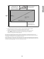
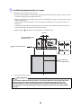
Diagonal image size and mounting position
The numbers on the slider measure (b) are the same as the projection distance (a) when the diagonal image
size (S) is 70 inches or more. Because the installation position of the projector changes when (S) is less than 70
inches, the numbers for (a) and (b) differ.
In order to see the stamp and the numbers on the slider scale, you need to slide out the arm extension.
When the diagonal image size is 70 inches or more, mount the 3-axis adjustment unit at the position marked
with a stamp.
When the diagonal image size is less than 70 inches, mount the 3-axis adjustment unit at the position marked
with a stamp.
Wall plate
Projection surface
Offset value for the position of the
center of the screen and the center of
the wall plate
Distance from wall to
projection surface
2.8 in. (70.5 mm)
8.6 in.
(218 mm)

15
English
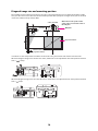
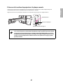
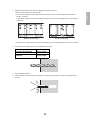
Distance from projection surface to wall plate
The distance (c) from the projection surface to the wall plate is the number given when the vertical slide is set
to the base position, as shown below.
Match the notch on the wall mount to the position of the stamp on the wall plate.
The measurements may differ depending on the location where you place the
projector.
When projecting in Tele, the quality of the projected images may decrease.
When using BrightLink Pro 1410Wi, BrightLink 475Wi/485Wi, or PowerLite 475W/
485W to project images at a 4:3 aspect ratio, the images are resized automatically and
the quality of the projected images may decrease.
Base position
Stamp on plate
Notch on mount arm

16
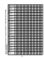
Installation Measurements in Inches for BrighLink Pro 1410Wi, BrightLink 475Wi/485Wi and PowerLite 475W/485W
Diagonal
image size
(S)
16:10 WXGA 4:3 XGA 16:9 Widescreen
Min.
ceiling
height*
Image
width
(w)
Image
height
(h)
Min.
projection
distance (a)
Slider
scale
mark
(b)
Distance
from top of
image to
wall plate
(c)
Min.
ceiling
height*
Image
width
(w)
Image
height
(h)
Min.
projection
distance (a)
Slider
scale
mark
(b)
Distance
from top of
image to
wall plate
(c)
Min.
ceiling
height*
Image
width
(w)
Image
height
(h)
Min.
projection
distance (a)
Slider
scale
mark
(b)
Distance
from top
of image
to wall
plate (c)
53” ———— ——
78.7 42.4 31.8 2.5 4.9 6.9 — — — — — —
54” ———— ——
79.4 43.2 32.4 2.7 5.2 7.0 — — — — — —
55” ———— ——
80.1 44.0 33.0 3.0 5.5 7.1 — — — — — —
56” ———— ——
80.8 44.8 33.6 3.3 5.7 7.2 — — — — — —
57” ———— ——
81.5 45.6 34.2 3.6 6.0 7.3 — — — — — —
58” ———— ——
82.3 46.4 34.8 3.8 6.3 7.5 — — — — — —
59” ———— ——
83.0 47.2 35.4 4.1 6.6 7.6 77.5 51.4 28.9 2.6 5.1 8.5
60”
78.7 50.9 31.8 2.5 4.9 6.9 83.7 48.0 36.0 4.4 6.8 7.7 78.1 52.3 29.4 2.9 5.3 8.7
61”
79.3 51.7 32.3 2.7 5.1 7.0 84.4 48.8 36.6 4.7 7.1 7.8 78.7 53.2 29.9 3.1 5.6 8.8
62”
79.9 52.6 32.9 3.0 5.4 7.1 85.1 49.6 37.2 5.0 7.4 7.9 79.3 54.0 30.4 3.4 5.8 8.9
63”
80.6 53.4 33.4 3.2 5.6 7.2 85.8 50.4 37.8 5.2 7.7 8.0 80.0 54.9 30.9 3.6 6.1 9.1
64”
81.2 54.3 33.9 3.4 5.9 7.3 86.6 51.2 38.4 5.5 7.9 8.2 80.6 55.8 31.4 3.9 6.3 9.2
65”
81.8 55.1 34.4 3.7 6.1 7.4 87.3 52.0 39.0 5.8 8.2 8.3 81.2 56.7 31.9 4.1 6.6 9.3
66”
82.5 56.0 35.0 3.9 6.4 7.5 88.0 52.8 39.6 6.1 8.5 8.4 81.8 57.5 32.4 4.4 6.8 9.5
67”
83.1 56.8 35.5 4.2 6.6 7.6 88.7 53.6 40.2 6.3 8.8 8.5 82.5 58.4 32.9 4.6 7.1 9.6
68”
83.7 57.7 36.0 4.4 6.9 7.7 89.4 54.4 40.8 6.6 9.1 8.6 83.1 59.3 33.3 4.9 7.3 9.7
69”
84.4 58.5 36.6 4.7 7.1 7.8 90.2 55.2 41.4 6.9 9.3 8.8 83.7 60.1 33.8 5.1 7.6 9.9
70”
85.0 59.4 37.1 4.9 4.9 7.9 90.9 56.0 42.0 7.2 7.2 8.9 84.3 61.0 34.3 5.4 5.4 10.0
71”
85.6 60.2 37.6 5.1 5.1 8.0 91.6 56.8 42.6 7.4 7.4 9.0 85.0 61.9 34.8 5.6 5.6 10.2
72”
86.3 61.1 38.2 5.4 5.4 8.1 92.3 57.6 43.2 7.7 7.7 9.1 85.6 62.8 35.3 5.9 5.9 10.3
73”
86.9 61.9 38.7 5.6 5.6 8.2 93.0 58.4 43.8 8.0 8.0 9.2 86.2 63.6 35.8 6.1 6.1 10.4
74”
87.5 62.8 39.2 5.9 5.9 8.3 93.8 59.2 44.4 8.3 8.3 9.4 86.8 64.5 36.3 6.4 6.4 10.6
75”
88.2 63.6 39.7 6.1 6.1 8.4 94.5 60.0 45.0 8.5 8.5 9.5 87.5 65.4 36.8 6.6 6.6 10.7
76”
88.8 64.4 40.3 6.4 6.4 8.5 95.2 60.8 45.6 8.8 8.8 9.6 88.1 66.2 37.3 6.9 6.9 10.8

17
English
* Based on an image 30 inches from the floor; if the image is lower, the minimum ceiling height is reduced by the corresponding measurement.
77” 89.5 65.3 40.8 6.6 6.6 8.6 95.9 61.6 46.2 9.1 9.1 9.7 88.7 67.1 37.8 7.1 7.1 11.0
78”
90.1 66.1 41.3 6.9 6.9 8.8 96.6 62.4 46.8 9.4 9.4 9.8 89.3 68.0 38.2 7.4 7.4 11.1
79”
90.7 67.0 41.9 7.1 7.1 8.9 97.4 63.2 47.4 9.7 9.7 10.0 90.0 68.9 38.7 7.6 7.6 11.2
80”
91.4 67.8 42.4 7.3 7.3 9.0 98.1 64.0 48.0 9.9 9.9 10.1 90.6 69.7 39.2 7.9 7.9 11.4
81”
92.0 68.7 42.9 7.6 7.6 9.1 98.8 64.8 48.6 10.2 10.2 10.2 91.2 70.6 39.7 8.1 8.1 11.5
82”
92.6 69.5 43.5 7.8 7.8 9.2 99.5 65.6 49.2 10.5 10.5 10.3 91.8 71.5 40.2 8.4 8.4 11.6
83”
93.3 70.4 44.0 8.1 8.1 9.3 100.2 66.4 49.8 10.8 10.8 10.4 92.5 72.3 40.7 8.6 8.6 11.8
84”
93.9 71.2 44.5 8.3 8.3 9.4 100.9 67.2 50.4 11.0 11.0 10.5 93.1 73.2 41.2 8.9 8.9 11.9
85”
94.5 72.1 45.0 8.6 8.6 9.5 101.7 68.0 51.0 11.3 11.3 10.7 93.7 74.1
41.7
9.1 9.1 12.0
86”
95.2 72.9 45.6 8.8 8.8 9.6 102.4 68.8 51.6 11.6 11.6 10.8 94.3 75.0
42.2
9.4 9.4 12.2
87”
95.8 73.8 46.1 9.1 9.1 9.7 103.1 69.6 52.2 11.9 11.9 10.9 95.0 75.8
42.7
9.6 9.6 12.3
88”
96.4 74.6 46.6 9.3 9.3 9.8 103.8 70.4 52.8 12.1 12.1 11.0 95.6 76.7
43.1
9.9 9.9 12.5
89”
97.1 75.5 47.2 9.5 9.5 9.9 — — — — — — 96.2 77.6
43.6
10.2 10.2 12.6
90”
97.7 76.3 47.7 9.6 9.6 10.0 — — — — — — 96.8 78.4
44.1
10.4 10.4 12.7
91”
98.3 77.2 48.2 10.0 10.0 10.1 — — — — — — 97.5 79.3
44.6
10.7 10.7 12.9
92”
99.0 78.0 48.8 10.3 10.3 10.2 — — — — — — 98.1 80.2 45.1 10.9 10.9 13.0
93”
99.6 78.9 49.3 10.5 10.5 10.3 — — — — — — 98.7 81.1 45.6 11.2 11.2 13.1
94”
100.3 79.7 49.8 10.8 10.8 10.4 — — — — — — 99.3 81.9 46.1 11.4 11.4 13.3
95”
100.9 80.6 50.3 11.0 11.0 10.5 — — — — — — 100.0 82.8 46.6 11.7 11.7 13.4
96”
101.5 81.4 50.9 11.3 11.3 10.6 — — — — — — 100.6 83.7 47.1 11.9 11.9 13.5
97”
102.2 82.3 51.4 11.5 11.5 10.7 — — — — — — 101.2 84.5 47.6 12.2 12.2 13.7
98”
102.8 83.1 51.9 11.7 11.7 10.9 — — — — — — — — — — — —
99”
103.4 84.0 52.5 12.0 12.0 11.0 — — — — — — — — — — — —
100”
104.1 84.8 53.0 12.2 12.2 11.1 — — — — — — — — — — — —
Diagonal
image size
(S)
16:10 WXGA 4:3 XGA 16:9 Widescreen
Min.
ceiling
height*
Image
width
(w)
Image
height
(h)
Min.
projection
distance (a)
Slider
scale
mark
(b)
Distance
from top of
image to
wall plate
(c)
Min.
ceiling
height*
Image
width
(w)
Image
height
(h)
Min.
projection
distance (a)
Slider
scale
mark
(b)
Distance
from top of
image to
wall plate
(c)
Min.
ceiling
height*
Image
width
(w)
Image
height
(h)
Min.
projection
distance (a)
Slider
scale
mark
(b)
Distance
from top
of image
to wall
plate (c)

18
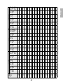
Installation Measurements in Inches for BrightLink 480i and PowerLite 470/480
Diagonal
image size
(S)
4:3 XGA 16:10 WXGA 16:9 Widescreen
Min.
ceiling
height*
Image
width
(w)
Image
height
(h)
Min.
projection
distance (a)
Slider
scale
mark
(b)
Distance
from top of
image to
wall plate
(c)
Min.
ceiling
height*
Image
width
(w)
Image
height
(h)
Min.
projection
distance (a)
Slider
scale
mark
(b)
Distance
from top
of image
to wall
plate (c)
Min.
ceiling
height*
Image
width
(w)
Image
height
(h)
Min.
projection
distance (a)
Slider
scale
mark
(b)
Distance
from top
of image
to wall
plate (c)
52” ———— —— ———— ——
75.8 45.3 25.5 2.6 5.1 10.3
53” ———— ——
77.2 44.9 28.1 2.5 5.0 8.8 76.4 46.2 26.0 2.9 5.4 10.5
54” ———— ——
77.9 45.8 28.6 2.8 5.2 9.0 77.1 47.1 26.5 3.2 5.7 10.7
55” ———— ——
78.6 46.6 29.2 3.1 5.5 9.1 77.8 47.9 27.0 3.5 5.9 10.8
56”
80 44.8 33.6 2.5 4.9 6.0 79.3 47.5 29.7 3.4 5.8 9.3 78.5 48.8 27.5 3.8 6.2 11.0
57”
80 45.6 34.2 2.7 5.2 6.1 80.0 48.3 30.2 3.6 6.1 9.4 79.2 49.7 27.9 4.1 6.5 11.2
58”
81 46.4 34.8 3.0 5.4 6.2 80.7 49.2 30.7 3.9 6.3 9.6 79.8 50.6 28.4 4.4 6.8 11.4
59”
82 47.2 35.4 3.3 5.7 6.3 81.4 50.0 31.3 4.2 6.6 9.7 80.5 51.4 28.9 4.6 7.1 11.6
60”
82 48.0 36.0 3.5 6.0 6.4 82.0 50.9 31.8 4.5 6.9 9.9 81.2 52.3 29.4 4.9 7.4 11.8
61”
83 48.8 36.6 3.8 6.2 6.5 82.7 51.7 32.3 4.7 7.2 10.0 81.9 53.2 29.9 5.2 7.7 12.0
62”
84 49.6 37.2 4.1 6.5 6.6 83.4 52.6 32.9 5.0 7.5 10.2 82.6 54.0 30.4 5.5 7.9 12.2
63”
84 50.4 37.8 4.3 6.7 6.6 84.1 53.4 33.4 5.3 7.7 10.4 83.2 54.9 30.9 5.8 8.2 12.3
64”
85 51.2 38.4 4.6 7.0 6.7 84.8 54.3 33.9 5.6 8.0 10.5 83.9 55.8 31.4 6.1 8.5 12.5
65”
86 52.0 39.0 4.8 7.3 6.8 85.5 55.1 34.4 5.8 8.3 10.7 84.6 56.7 31.9 6.4 8.8 12.7
66”
87 52.8 39.6 5.1 7.5 6.9 86.2 56.0 35.0 6.1 8.6 10.8 85.3 57.5 32.4 6.6 9.1 12.9
67”
87 53.6 40.2 5.4 7.8 7.0 86.9 56.8 35.5 6.4 8.8 11.0 85.9 58.4 32.9 6.9 9.4 13.1
68”
88 54.4 40.8 5.6 8.1 7.1 87.6 57.7 36.0 6.7 9.1 11.1 86.6 59.3 33.3 7.2 9.6 13.3
69”
89 55.2 41.4 5.9 8.3 7.2 88.3 58.5 36.6 7.0 9.4 11.3 87.3 60.1 33.8 7.5 9.9 13.5
70”
89 56.0 42.0 6.1 6.1 7.3 89.0 59.4 37.1 7.2 7.2 11.4 88.0 61.0 34.3 7.8 7.8 13.7
71”
90 56.8 42.6 6.4 6.4 7.4 89.7 60.2 37.6 7.5 7.5 11.6 88.6 61.9 34.8 8.1 8.1 13.8
72”
91 57.6 43.2 6.7 6.7 7.5 90.3 61.1 38.2 7.8 7.8 11.8 89.3 62.8 35.3 8.3 8.3 14.0
73”
91 58.4 43.8 6.9 6.9 7.6 91.0 61.9 38.7 8.1 8.1 11.9 90.0 63.6 35.8 8.6 8.6 14.2
74”
92 59.2 44.4 7.2 7.2 7.7 91.7 62.8 39.2 8.3 8.3 12.1 90.7 64.5 36.3 8.9 8.9 14.4

19
English
* Based on an image 30 inches from the floor; if the image is lower, the minimum ceiling height is reduced by the corresponding measurement.
75” 93 60.0 45.0 7.4 7.4 7.8 92.4 63.6 39.7 8.6 8.6 12.2 91.4 65.4 36.8 9.2 9.2 14.6
76”
94 60.8 45.6 7.7 7.7 7.9 93.1 64.4 40.3 8.9 8.9 12.4 92.0 66.2 37.3 9.5 9.5 14.8
77”
94 61.6 46.2 8.0 8.0 8.0 93.8 65.3 40.8 9.2 9.2 12.5 92.7 67.1 37.8 9.8 9.8 15.0
78”
95 62.4 46.8 8.2 8.2 8.1 94.5 66.1 41.3 9.5 9.5 12.7 93.4 68.0 38.2 10.1 10.1 15.1
79”
96 63.2 47.4 8.5 8.5 8.2 95.2 67.0 41.9 9.7 9.7 12.8 94.1 68.9 38.7 10.3 10.3 15.3
80”
96 64.0 48.0 8.8 8.8 8.3 95.9 67.8 42.4 10.0 10.0 13.0 94.7 69.7 39.2 10.6 10.6 15.5
81”
97 64.8 48.6 9.0 9.0 8.4 96.6 68.7 42.9 10.3 10.3 13.2 95.4 70.6 39.7 10.9 10.9 15.7
82”
98 65.6 49.2 9.3 9.3 8.5 97.3 69.5 43.5 10.6 10.6 13.3 96.1 71.5 40.2 11.2 11.2 15.9
83”
98 66.4 49.8 9.5 9.5 8.6 98.0 70.4 44.0 10.8 10.8 13.5 96.8 72.3 40.7 11.5 11.5 16.1
84”
99 67.2 50.4 9.8 9.8 8.7 98.7 71.2 44.5 11.1 11.1 13.6 97.5 73.2 41.2 11.8 11.8 16.3
85”
100 68.0 51.0 10.1 10.1 8.8 99.3 72.1 45.0 11.4 11.4 13.8 98.1 74.1
41.7
12.1 12.1 16.5
86”
100 68.8 51.6 10.3 10.3 8.9 100.0 72.9 45.6 11.7 11.7 13.9 — —
—
———
87”
101 69.6 52.2 10.6 10.6 9.0 100.7 73.8 46.1 12.0 12.0 14.1 — —
—
———
88”
102 70.4 52.8 10.9 10.9 9.1 101.4 74.6 46.6 12.2 12.2 14.2 — —
—
———
89”
103 71.2 53.4 11.1 11.1 9.2 — — — — — — — —
—
———
90”
103 72.0 54.0 11.4 11.4 9.3 — — — — — — — —
—
———
91”
104 72.8 54.6 11.6 11.6 9.4 — — — — — — — —
—
———
92”
105 73.6 55.2 11.9 11.9 9.5 — — — — — — — — — — — —
93”
105 74.4 55.8 12.2 12.2 9.6 — — — — — — — — — — — —
Diagonal
image size
(S)
4:3 XGA 16:10 WXGA 16:9 Widescreen
Min.
ceiling
height*
Image
width
(w)
Image
height
(h)
Min.
projection
distance (a)
Slider
scale
mark
(b)
Distance
from top of
image to
wall plate
(c)
Min.
ceiling
height*
Image
width
(w)
Image
height
(h)
Min.
projection
distance (a)
Slider
scale
mark
(b)
Distance
from top
of image
to wall
plate (c)
Min.
ceiling
height*
Image
width
(w)
Image
height
(h)
Min.
projection
distance (a)
Slider
scale
mark
(b)
Distance
from top
of image
to wall
plate (c)

20
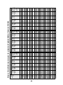
Installation Measurements in MM for BrightLink Pro 1410Wi, BrightLink 475Wi/485Wi and PowerLite 475W/485W
Diagonal
image size
(S)
16:10 WXGA 4:3 XGA 16:9 Widescreen
Min.
ceiling
height*
Image
width
(w)
Image
height
(h)
Min.
projection
distance (a)
Slider
scale
mark
(b)
Distance
from top
of image
to wall
plate (c)
Min.
ceiling
height*
Image
width
(w)
Image
height
(h)
Min.
projection
distance (a)
Slider
scale
mark
(b)
Distance
from top
of image
to wall
plate (c)
Min.
ceiling
height*
Image
width
(w)
Image
height
(h)
Min.
Projection
distance (a)
Slider
scale
mark
(b)
Distance
from top
of image
to wall
plate (c)
53” ———— ——
1998 1077 808 62 124 174 — — — — — —
54” ———— ——
2016 1097 823 69 131 177 — — — — — —
55” ———— ——
2034 1118 838 76 138 180 — — — — — —
56” ———— ——
2052 1138 853 83 145 183 — — — — — —
57” ———— ——
2071 1158 869 91 153 186 — — — — — —
58” ———— ——
2089 1179 884 98 160 189 — — — — — —
59” ———— ——
2107 1199 899 105 167 192 1968 1306 735 66 128 217
60”
1998 1292 808 62 124 174 2125 1219 914 112 174 195 1983 1328 747 73 135 220
61”
2014 1314 821 69 131 177 2144 1240 930 119 181 198 1999 1350 760 79 141 223
62”
2030 1335 835 75 137 179 2162 1260 945 126 188 201 2015 1373 772 86 148 227
63”
2046 1357 848 81 143 182 2180 1280 960 133 195 204 2031 1395 785 92 154 230
64”
2063 1379 862 87 149 185 2198 1300 975 140 202 207 2047 1417 797 98 160 234
65”
2078 1400 875 93 155 187 2217 1321 991 147 209 210 2062 1439 809 105 167 237
66”
2094 1422 888 100 162 190 2235 1341 1006 154 216 213 2079 1461 822 111 173 241
67”
2111 1443 902 106 168 193 2253 1361 1021 161 223 216 2094 1483 834 117 179 244
68”
2126 1465 915 112 174 195 2271 1382 1036 168 230 219 2111 1505 847 124 186 248
69”
2143 1486 929 118 180 198 2290 1402 1052 175 237 222 2126 1528 859 130 192 251
70”
2159 1508 942 124 124 201 2308 1422 1067 182 182 225 2142 1550 872 137 137 254
71”
2175 1529 956 131 131 203 2326 1443 1082 189 189 228 2158 1572 884 143 143 258
72”
2191 1551 969 137 137 206 2345 1463 1097 196 196 232 2174 1594 897 149 149 261
73”
2208 1572 983 143 143 209 2364 1483 1113 203 203 235 2190 1616 909 156 156 265
74”
2223 1594 996 149 149 211 2382 1504 1128 210 210 238 2205 1638 921 162 162 268
75”
2240 1615 1010 155 155 214 2400 1524 1143 217 217 241 2222 1660 934 168 168 272
76”
2256 1637 1023 162 162 217 2418 1544 1158 224 224 244 2237 1682 946 175 175 275
La page est en cours de chargement...
La page est en cours de chargement...
La page est en cours de chargement...
La page est en cours de chargement...
La page est en cours de chargement...
La page est en cours de chargement...
La page est en cours de chargement...
La page est en cours de chargement...
La page est en cours de chargement...
La page est en cours de chargement...
La page est en cours de chargement...
La page est en cours de chargement...
La page est en cours de chargement...
La page est en cours de chargement...
La page est en cours de chargement...
La page est en cours de chargement...
La page est en cours de chargement...
La page est en cours de chargement...
La page est en cours de chargement...
La page est en cours de chargement...
La page est en cours de chargement...
La page est en cours de chargement...
La page est en cours de chargement...
La page est en cours de chargement...
La page est en cours de chargement...
La page est en cours de chargement...
La page est en cours de chargement...
La page est en cours de chargement...
La page est en cours de chargement...
La page est en cours de chargement...
La page est en cours de chargement...
La page est en cours de chargement...
La page est en cours de chargement...
La page est en cours de chargement...
La page est en cours de chargement...
La page est en cours de chargement...
La page est en cours de chargement...
La page est en cours de chargement...
La page est en cours de chargement...
La page est en cours de chargement...
La page est en cours de chargement...
La page est en cours de chargement...
La page est en cours de chargement...
La page est en cours de chargement...
La page est en cours de chargement...
La page est en cours de chargement...
La page est en cours de chargement...
La page est en cours de chargement...
La page est en cours de chargement...
La page est en cours de chargement...
La page est en cours de chargement...
La page est en cours de chargement...
La page est en cours de chargement...
La page est en cours de chargement...
La page est en cours de chargement...
La page est en cours de chargement...
La page est en cours de chargement...
La page est en cours de chargement...
La page est en cours de chargement...
La page est en cours de chargement...
La page est en cours de chargement...
La page est en cours de chargement...
La page est en cours de chargement...
La page est en cours de chargement...
La page est en cours de chargement...
La page est en cours de chargement...
La page est en cours de chargement...
La page est en cours de chargement...
La page est en cours de chargement...
La page est en cours de chargement...
La page est en cours de chargement...
La page est en cours de chargement...
-
 1
1
-
 2
2
-
 3
3
-
 4
4
-
 5
5
-
 6
6
-
 7
7
-
 8
8
-
 9
9
-
 10
10
-
 11
11
-
 12
12
-
 13
13
-
 14
14
-
 15
15
-
 16
16
-
 17
17
-
 18
18
-
 19
19
-
 20
20
-
 21
21
-
 22
22
-
 23
23
-
 24
24
-
 25
25
-
 26
26
-
 27
27
-
 28
28
-
 29
29
-
 30
30
-
 31
31
-
 32
32
-
 33
33
-
 34
34
-
 35
35
-
 36
36
-
 37
37
-
 38
38
-
 39
39
-
 40
40
-
 41
41
-
 42
42
-
 43
43
-
 44
44
-
 45
45
-
 46
46
-
 47
47
-
 48
48
-
 49
49
-
 50
50
-
 51
51
-
 52
52
-
 53
53
-
 54
54
-
 55
55
-
 56
56
-
 57
57
-
 58
58
-
 59
59
-
 60
60
-
 61
61
-
 62
62
-
 63
63
-
 64
64
-
 65
65
-
 66
66
-
 67
67
-
 68
68
-
 69
69
-
 70
70
-
 71
71
-
 72
72
-
 73
73
-
 74
74
-
 75
75
-
 76
76
-
 77
77
-
 78
78
-
 79
79
-
 80
80
-
 81
81
-
 82
82
-
 83
83
-
 84
84
-
 85
85
-
 86
86
-
 87
87
-
 88
88
-
 89
89
-
 90
90
-
 91
91
-
 92
92


Epson BrightLink 475Wi Guide d'installation
- Catégorie
- Projecteurs de données
- Taper
- Guide d'installation
dans d''autres langues
Documents connexes
-
Epson PowerLite 1220 Multimedia Projector Supplemental Information
-
Epson BrightLink Pro 1410Wi Supplement
-
Epson BrightLink Pro 1470Ui Guide d'installation
-
-
-
-
-
Epson BrightLink 450Wi Guide d'installation
-
Epson V11H281020 - PowerLite 400W WXGA LCD Projector Mode d'emploi
-
Epson BrightLink 595Wi Guide d'installation
Autres documents
-
Polk Audio 265-RT Mounting Templates
-
Casio YM-80 Mode d'emploi
-
Casio YM-81 Mode d'emploi
-
-
MCL 8SP-TAB Fiche technique
-
Sharp ANSV100T Mode d'emploi
-
 SCS Sentinel 3245060990107 Le manuel du propriétaire
-
STEINEL IR Quattro 8m DALI-2 APC Manuel utilisateur
-
Infocus INL148HDUST Mode d'emploi
-
Dometic 520300, 520310, 520315, 520316, 521515, 521516, 521700, 521710, 521715, 521716, 531515, 531516, 531715, 531716, 600312, 600315, 620412, 620415, 620425, 620426, 620515, 620525, 620526, 620712, 620715, 620725, 620726, 630515, 630516 Mode d'emploi
