Panasonic NNTK922SS Le manuel du propriétaire

Taper
Le manuel du propriétaire
Installation Instructions
Notice d’installation
Instrucciones para la instalación
Cabinet
Armoire
Gabinete
Trim kit
Nécessaire d’encastrement
Juego de acabados
30" (762 mm)
30 po (762 mm)
30" (762 mm)
NN-TK932S
NN-TK732S
27" (686 mm)
27 po (686 mm)
27" (686 mm)
NN-TK922S
NN-TK722S
© Panasonic Appliances Microwave Oven (Shanghai) Co., Ltd. 2012
Read carefully and keep these installation instructions.
Lisez attentivement et conservez cette notice d'installation.
Lea cuidadosamente y guarde este instructivo de
instalación para su referencia.
IP4103_F0313BE00AP_16_120306.indd 1IP4103_F0313BE00AP_16_120306.indd 1 2012-3-6 Lynn 4:52:312012-3-6 Lynn 4:52:31
1
Contents
Caution ..............................................................................................................................................1-3
Step 1. Unpacking List..........................................................................................................................4
Step 2. Feature Diagram ......................................................................................................................5
Step 3. Cabinet Preparation ..............................................................................................................6-9
Step 4. Microwave Oven Installation .............................................................................................10-11
Step 5. Cabinet Installation............................................................................................................12-14
Step 6. Finishing Installation..........................................................................................................15-17
Caution
1. Read and follow all instructions completely.
2. This trim kit can be installed into a cabinet. The cabinet opening must have the following internal
dimensions as shown in g 1, P6 - P9.
MINIMUM INSTALLATION HEIGHT 36¼" (920 mm).
3. This Trim Kit is designed for use only with the Panasonic Microwave Oven Models listed.
4. For safe use of your oven, DO NOT alter or modify any part of this kit or oven.
5. Oven must be used with a properly grounded receptacle. Refer to operating instructions to
determine the correct electrical requirements.
6. Observe all applicable building and electrical codes.
7. The oven must be unplugged before attempting the installation of this kit.
8. The supporting shelf must be capable of supporting 100 lbs (45 kg).
9. Save these instructions for local inspection and relocation of oven.
TAKE CARE NOT TO KINK OR TRAP THE MICROWAVE ELECTRICAL CABLE.
The diagram may vary from the actual unit and is only for your reference.
Trim kit Oven
NN-TK932S
NN-TK922S
NN-SE9**S
NN-SD9**S
NN-SN9**S
NN-ST9**S
NN-TK732S
NN-TK722S
NN-SE7**S
NN-SD7**S
NN-SN7**S
IP4103_F0313BE00AP_16_120306.indd Sec1:1IP4103_F0313BE00AP_16_120306.indd Sec1:1 2012-3-6 Lynn 4:52:312012-3-6 Lynn 4:52:31
2
Table des matières
Mise en garde ....................................................................................................................................1-3
Étape 1. Liste des pièces ..................................................................................................................4
Étape 2. Schéma d’ensemble ............................................................................................................5
Étape 3. Préparatifs de l’armoire ....................................................................................................6-9
Étape 4. Installation du four à micro-ondes ................................................................................10-11
Étape 5. Installation de l’armoire ................................................................................................12-14
Étape 6. Fin de l’installation ........................................................................................................15-17
Mises en garde
1. Lire attentivement la présente notice et suivre les instructions.
2.
Ce nécessaire d’installation peut être installé dans une armoire. L’ouverture de l’armoire doit avoir
les dimensions internes indiquées à la g 1., P6 - P9.
HAUTEUR MINIMUM REQUISE : 920 mm (36 ¼ po)
3. Ce nécessaire d’encastrement est conçu pour utilisation seulement avec les modèles de fours à
micro-ondes Panasonic identiés dans la présente notice.
4. An d’assurer le fonctionnement sécuritaire du four, ne modier aucune pièce de ce nécessaire
ni du four.
5. Le four doit être branché dans une prise secteur avec mise à la terre. Se reporter au manuel
d’utilisation pour connaître les spécications électriques.
6. Respecter tous les codes de bâtiment et d’électricité applicables.
7. Le four doit être débranché avant d’installer le nécessaire d’encastrement.
8. La tablette doit pouvoir supporter une charge de 45 kg (100 lb).
9. Conserver cette notice aux ns d’inspection locale et dans l’éventualité où le four devrait être
déplacé et installé ailleurs.
PRENDRE GARDE À NE PAS PLIER OU COINCER LE CORDON D’ALIMENTATION DU FOUR.
Les illustrations peuvent ne pas donner une représentation dèle de l’appareil et ne sont
fournies qu’à titre indicatif.
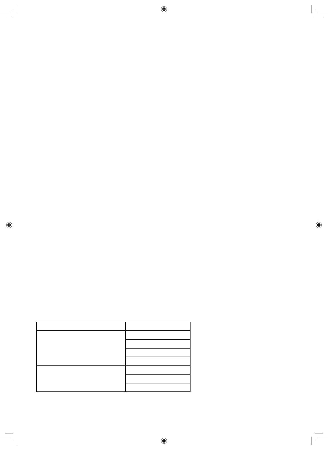
Nécessaire d’encastrement Modèles de fours
NN-TK932S
NN-TK922S
NN-SE9**S
NN-SD9**S
NN-SN9**S
NN-ST9**S
NN-TK732S
NN-TK722S
NN-SE7**S
NN-SD7**S
NN-SN7**S
IP4103_F0313BE00AP_16_120306.indd Sec1:2IP4103_F0313BE00AP_16_120306.indd Sec1:2 2012-3-6 Lynn 4:52:312012-3-6 Lynn 4:52:31
3
Índice
Precauciones .....................................................................................................................................1-3
Paso 1. Lista de desempaque ..............................................................................................................4
Paso 2. Esquema de funciones ............................................................................................................5
Paso 3. Preparación del gabinete ....................................................................................................6-9
Paso 4. Instalación del horno microondas.....................................................................................10-11
Paso 5. Instalación del gabinete....................................................................................................12-14
Paso 6. Finalización de la instalación ...........................................................................................15-17
Precauciones
1. Lea y siga todas las instrucciones.
2. Este juego de acabados puede instalarse dentro del gabinete. La abertura del gabinete debe tener
las siguientes dimensiones internas, como se muestra en la g 1, P6 - P9.
ALTURA MÍNIMA PARA LA INSTALACIÓN 36¼" (920 mm).
3.
Este juego de acabados está diseñado para utilizarse solo con los modelos de horno microondas
de Panasonic que se enumeran.
4. Para una utilización segura del horno, NO cambie ni modique ninguna parte de este juego o del
horno.
5. El horno debe utilizarse con un tomacorriente correctamente conectado a tierra. Consulte las
instrucciones de funcionamiento para determinar los requisitos eléctricos correctos.
6. Respete todos los códigos de construcción y eléctricos.
7. El horno debe estar desconectado antes de intentar instalar este juego.
8. El estante de soporte debe poder sostener 100 lbs (45kg).
9. Conserve estas instrucciones para realizar una inspección local o para trasladar el horno.
TENGA CUIDADO DE NO ENREDAR O APRISIONAR EL CABLE DE SUMINISTRO ELÉCTRICO
DEL MICROONDAS.
El esquema puede variar según la unidad real y es solo para su referencia.
Kit de cuidado Horno
NN-TK932S
NN-TK922S
NN-SE9**S
NN-SD9**S
NN-SN9**S
NN-ST9**S
NN-TK732S
NN-TK722S
NN-SE7**S
NN-SD7**S
NN-SN7**S
IP4103_F0313BE00AP_16_120306.indd Sec1:3IP4103_F0313BE00AP_16_120306.indd Sec1:3 2012-3-6 Lynn 4:52:312012-3-6 Lynn 4:52:31
4
Step 1. Unpacking List
Tools Needed: Measuring tape, Pencil , Phillips Screwdriver, Ø 2 mm (
5
/
64
" ) drill
Étape 1. Liste des pièces
Outils requis: Ruban (de mesurage), crayon, tournevis Phillips, perceuse avec mèche de Ø 2 mm (
5
/
64
po )
Paso 1. Lista de desempaque
Herramientas necesarias: Cinta métrica, Lápiz, Destornillador, Taladro Ø 2 mm (
5
/
64
)
Parts Supplied Pièces fournies Piezas suministradas
PART/PIÈCE/PIEZA
QUANTITY/QUANTITÉ/
CANTIDAD
Trim Frame
Cadre d’encastrement
Marco del acabado
1
Left Duct
Conduit du côté gauche
Conducto izquierdo
1
Base Bracket Assembly
Base des supports de montage
Base Bracket Assembly
1
Bracket
Support
Ménsula
4
Catch
Loquet
Pestillo
4
Screw
Vis
Tornillo
10
Strike
Gâche
Tarugo
4
Cushion
Cushion
Cushion
2
IP4103_F0313BE00AP_16_120306.indd Sec1:4IP4103_F0313BE00AP_16_120306.indd Sec1:4 2012-3-6 Lynn 4:52:312012-3-6 Lynn 4:52:31
5
Step 2. Feature Diagram
Installed Image
Étape 2. Schéma d’ensemble
Ensemble installé
Paso 2. Esquema de funciones
Imagen de la instalación
Trim Kit Dimensions
TK932S TK922S TK732S TK722S
Width 30" (760 mm) 27" (684 mm) 30" (760 mm) 27" (684 mm)
Height 18
9
/
16
" (472 mm) 18
9
/
16
" (472 mm) 16 ½" (419 mm) 16 ½" (419 mm)
Depth (Thickness) ¾" (20 mm) ¾" (20 mm) ¾" (20 mm) ¾" (20 mm)
Dimensions du nécessaire d’encastrement
TK932S TK922S TK732S TK722S
Largeur 760 mm (30 po) 684 mm (27 po) 760 mm (30 po) 684 mm (27 po)
Hauteur 472 mm (18
9
/
16
po) 472 mm (18
9
/
16
po) 419 mm (16 ½ po) 419 mm (16 ½ po)
Profondeur (épaisseur) 20 mm (¾ po) 20 mm (¾ po) 20 mm (¾ po) 20 mm (¾ po)
Dimensiones del juego de acabados
TK932S TK922S TK732S TK722S
Ancho 30" (760 mm) 27" (684 mm) 30" (760 mm) 27" (684 mm)
Altura 18
9
/
16
" (472 mm) 18
9
/
16
" (472 mm) 16 ½" (419 mm) 16 ½" (419 mm)
Profundidad (grosor) ¾" (20 mm) ¾" (20 mm) ¾" (20 mm) ¾" (20 mm)
H
W
D
IP4103_F0313BE00AP_16_120306.indd Sec1:5IP4103_F0313BE00AP_16_120306.indd Sec1:5 2012-3-6 Lynn 4:52:312012-3-6 Lynn 4:52:31
6
min. 533 mm (21")
min. 920 mm (36
1
/4
")
442 mm
(17
3
/
8
")
± 2 mm
(15
5
/
16
"
±
5
/
64
")
724(28
1
/
2
"
)
+ 8 mm (
5
/
16
")
0 mm
fig 1.
Step 3-1. Cabinet Preparation (For TK932S)
Étape 3-1. Préparatifs de l’armoire (Pour TK932S)
Paso 3-1. Preparación del gabinete (
For TK932S)
IP4103_F0313BE00AP_16_120306.indd Sec1:6IP4103_F0313BE00AP_16_120306.indd Sec1:6 2012-3-6 Lynn 4:52:312012-3-6 Lynn 4:52:31
7
min. 533 mm (21")
min. 920 mm (36
1
/4
")
442mm(17
3
/
8
'') ± 2 mm
(15
5
/
16
"
±
5
/
64
")
648 (25
1
/
2
"
)
+ 8 mm (
5
/
16
")
0 mm
fig 1.
Step 3-2. Cabinet Preparation (For TK922S)
Étape 3-2. Préparatifs de l’armoire (Pour TK922S)
Paso 3-2. Preparación del gabinete (
For TK922S)
IP4103_F0313BE00AP_16_120306.indd Sec1:7IP4103_F0313BE00AP_16_120306.indd Sec1:7 2012-3-6 Lynn 4:52:312012-3-6 Lynn 4:52:31
8
min. 533 mm (21")
min. 920 mm (36
1
/4
")
389 mm ± 2 mm
(15
5
/
16
"
±
5
/
64
")
724(28
1
/
2
"
)
+ 8 mm (
5
/
16
")
0 mm
fig 1.
Step 3-3. Cabinet Preparation (For TK732S)
Étape 3-3. Préparatifs de l’armoire (Pour TK732S)
Paso 3-3. Preparación del gabinete (
For TK732S)
IP4103_F0313BE00AP_16_120306.indd Sec1:8IP4103_F0313BE00AP_16_120306.indd Sec1:8 2012-3-6 Lynn 4:52:312012-3-6 Lynn 4:52:31
9
min. 533 mm (21")
min. 920 mm (36
1
/4
")
389 mm ± 2 mm
(15
5
/
16
"
±
5
/
64
")
648 (25
1
/
2
"
)
+ 8 mm (
5
/
16
")
0 mm
fig 1.
Step 3-4. Cabinet Preparation (For TK722S)
Étape 3-4. Préparatifs de l’armoire (Pour TK722S)
Paso 3-4. Preparación del gabinete (
For TK722S)
IP4103_F0313BE00AP_16_120306.indd Sec1:9IP4103_F0313BE00AP_16_120306.indd Sec1:9 2012-3-6 Lynn 4:52:312012-3-6 Lynn 4:52:31
10
1.
2.
3.
4.
Step 4. Microwave Oven Installation
Étape 4. Installation du four à micro-ondes
Paso 4. Instalación del horno microondas
IP4103_F0313BE00AP_16_120306.indd Sec1:10IP4103_F0313BE00AP_16_120306.indd Sec1:10 2012-3-6 Lynn 4:52:312012-3-6 Lynn 4:52:31
11
5.
7.
6.
Step 4. Microwave Oven Installation
Étape 4. Installation du four à micro-ondes
Paso 4. Instalación del horno microondas
Put a piece of the cushion on the
top of oven and put a piece of the
cushion on left of oven and left
duct.
Put a piece of the cushion on the
top of oven and put a piece of the
cushion on left of oven and left
duct.
Put a piece of the cushion on the
top of oven and put a piece of the
cushion on left of oven and left
duct.
IP4103_F0313BE00AP_16_120306.indd Sec1:11IP4103_F0313BE00AP_16_120306.indd Sec1:11 2012-3-6 Lynn 4:52:312012-3-6 Lynn 4:52:31
12
Step 5. Cabinet Installation
Étape 5. Installation de l’armoire
Paso 5. Instalación del gabinete
Center Line of Cabinet
Ligne du centre de l’armoire
Eje de referencia (línea central) del gabinete
Position Base Bracket Assembly on cabinet shelf. The front end of Base Bracket Assembly
should align flush with the front edge of the shelf.
1. Aligning the base bracket assembly
1. Alignement de la base des supports de montage
1. Aligning the base bracket assembly
Positionner la base des supports de montage sur l’étagère de l’armoire. Le côté avant de la
base doit être aligné avec le rebord avant de l’étagère.
Position Base Bracket Assembly on cabinet shelf. The front end of Base Bracket Assembly
should align flush with the front edge of the shelf.
IP4103_F0313BE00AP_16_120306.indd Sec1:12IP4103_F0313BE00AP_16_120306.indd Sec1:12 2012-3-6 Lynn 4:52:312012-3-6 Lynn 4:52:31
13
Drill two pilot holes
Percer deux avant-trous
Haga dos agujeros guía
Drill bit
Foret
Broca
2x
ø 2 mm
(
5
/64")
Step 5. Cabinet Installation
Étape 5. Installation de l’armoire
Paso 5. Instalación del gabinete
2.
Attaching the base bracket assembly
Fixation de la base des supports de montage
Attaching the base bracket assembly
IP4103_F0313BE00AP_16_120306.indd Sec1:13IP4103_F0313BE00AP_16_120306.indd Sec1:13 2012-3-6 Lynn 4:52:312012-3-6 Lynn 4:52:31
14
4x
4x
4.
3.
Step 5. Cabinet Installation
Étape 5. Installation de l’armoire
Paso 5. Instalación del gabinete
4x
Bracket assembly
Attaching the bracket
Supports de montage
Fixation des supports de montage
Abrazadera de montaje
Fijación de la abrazadera
2 screws on each bracket
2 vis pour chaque support
2 tornillos en cada abrazadera
Drill bit
Foret
Broca
8x
ø 2 mm
(
5
/64")
IP4103_F0313BE00AP_16_120306.indd Sec1:14IP4103_F0313BE00AP_16_120306.indd Sec1:14 2012-3-6 Lynn 4:52:322012-3-6 Lynn 4:52:32
15
Step 6. Finishing Installation
Step 6. Fin de l’installation
Step 6. Finalización de la instalación
Trim Frame
Cadre d’encastrement
Marco del acabado
1.
Inserting strikes
Insertion des gâches
Inserción de ganchos de soporte
1-1
1-2
4X
IP4103_F0313BE00AP_16_120306.indd Sec1:15IP4103_F0313BE00AP_16_120306.indd Sec1:15 2012-3-6 Lynn 4:52:322012-3-6 Lynn 4:52:32
16
Step 6. Finishing Installation
Step 6. Fin de l’installation
Step 6. Finalización de la instalación
Complete the assembly
Montage du four
Completar el montaje
2.
Oven placement
Installation du four
Colocación del horno
IP4103_F0313BE00AP_16_120306.indd Sec1:16IP4103_F0313BE00AP_16_120306.indd Sec1:16 2012-3-6 Lynn 4:52:322012-3-6 Lynn 4:52:32
17
Step 6. Finishing Installation
Step 6. Fin de l’installation
Step 6. Finalización de la instalación
Complete the assembly
Montage du four
Completar el montaje
3.
Trim frame
installation
Installation du cadre
d'encastrement
Instalación
de marco
embellecedor
Note: Place the trim frame with the
extended lip at the bottom
Remarque: Installer le cadre
d’encastrement, côté
avec saillie vers le bas
Nota:
Coloque el armazón con el
borde extendido en el fondo
IP4103_F0313BE00AP_16_120306.indd Sec1:17IP4103_F0313BE00AP_16_120306.indd Sec1:17 2012-3-6 Lynn 4:52:322012-3-6 Lynn 4:52:32
F0313BE00AP
IP0312-0
Printed in China
Imprimé en Chine
Impreso en China
IP4103_F0313BE00AP_16_120306.indd Sec1:18IP4103_F0313BE00AP_16_120306.indd Sec1:18 2012-3-6 Lynn 4:52:322012-3-6 Lynn 4:52:32
  • Page 1 1
  • Page 2 2
  • Page 3 3
  • Page 4 4
  • Page 5 5
  • Page 6 6
  • Page 7 7
  • Page 8 8
  • Page 9 9
  • Page 10 10
  • Page 11 11
  • Page 12 12
  • Page 13 13
  • Page 14 14
  • Page 15 15
  • Page 16 16
  • Page 17 17
  • Page 18 18
  • Page 19 19

Panasonic NNTK922SS Le manuel du propriétaire

Taper
Le manuel du propriétaire

dans d''autres langues