
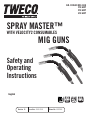
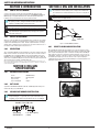
SPRAY MASTER™
WITH VELOCITY2 CONSUMABLES
MIG GUNS
Safety and
Operating
Instructions
AIR-COOLED MIG GUN
250 AMP
350 AMP
450 AMP
Revision: AD Issue Date: 20-06-2018 Manual No.: 89200016
CURRENT
450
AMPS
UP TO
WIRE SIZE
UP TO
3
/
32
"
(2.4 mm)
DUTY CYCL E
80
%
UP TO
English

WE APPRECIATE YOUR BUSINESS!
Congratulations on receiving your new Tweco Spray Master™ product.
We are proud to have you as our customer and will strive to provide
you with the best service and support in the industry. This product is
backed by our extensive warranty and world-wide service network.
We know you take pride in your work and we feel privileged to provide
you with this high performance product that will help you get the job
done.
For more than 75 years Tweco has provided quality products you can
trust, when your reputation is on the line.
YOU ARE IN GOOD COMPANY!
Tweco is a Global Brand of Arc Welding Products for ESAB. We
distinguish ourselves from our competition through market-leading
innovation and truly dependable products that will stand the test of
time.
We strive to enhance your productivity, efficiency and welding
performance, enabling you to excel in your craft. We design products
with the welder in mind delivering- advanced features, durability, ease
of use and ergonomic comfort.
Above all, we are committed to a safer working environment within
the welding industry. Your satisfaction with this product and its safe
operation is our ultimate concern. Please take the time to read the
entire manual, especially the Safety Precautions.
If you have any questions or concerns regarding your new Tweco
product, please contact our friendly and knowledgeable Customer
Service Team at:
1-800-462-2782 (USA) and 1-905-827-4515 (Canada),
or visit us on the web at www.esab.com/tweco.com

i
Spray Master
™
with VELOCITY2 MIG Guns
Safety and Operating Instructions
Instruction Guide Number: 89200016
Published by:
ESAB Group Inc.
2800 Airport Rd.
Denton, TX. 76207
(940) 566-2000
www.esab.com/tweco
U.S. Customer Care: (800) 426-1888
International Customer Care: (940) 381-1212
Canada Customer Care: 905-827-4515 / fax 800-588-1714
Copyright © 2014, 2015, 2018 ESAB. All rights reserved.
Reproduction of this work, in whole or in part, without written permission of the publisher is
prohibited.
The publisher does not assume and hereby disclaims any liability to any party for any loss
or damage caused by any error or omission in this Manual, whether such error results from
negligence, accident, or any other cause.
For Printing Material Specication refer to document 47X1920
Publication Date: May 15, 2014
Revision Date: 20-06-2018
Record the following information for Warranty purposes:
Where Purchased:
Purchase Date:
Equipment Serial #:
!
WARNING
Read and understand this entire Manual and your employer’s safety practices before installing, operating, or servic-
ing the equipment.
While the information contained in this Manual represents the Manufacturer's best judgment, the Manufacturer
assumes no liability for its use.

2
SECTION 1: SAFETY PRECAUTIONS
Table of Contents
SECTION 1: SAFETY PRECAUTIONS ..........................................................................2
Mesures de sécurité ......................................................................... 2
SECTION 2: INTRODUCTION ......................................................................................4
2.01 How to Use this Manual ................................................................... 4
2.02 Receipt of Equipment ....................................................................... 4
2.03 Description ....................................................................................... 4
SECTION 3: MIG GUN SPECIFICATIONS.....................................................................4
3.01 MIG Gun Classification ..................................................................... 4
3.02 Duty Cycle ........................................................................................ 4
3.03 MIG Gun Part Number Identification ................................................ 4
SECTION 4: MIG GUN INSTALLATION ........................................................................4
4.01 Direct Plug MIG Gun Installation ...................................................... 4
SECTION 5: SPRAY MASTER WITH VELOCITY2 MAINTENANCE ...............................5
5.01 Installing or Replacing VELOCITY2 Contact Tip ............................... 5
5.02 Conduit Identification ....................................................................... 5
Conduit Removal .............................................................................. 5
Conduit Installation .......................................................................... 5
5.03 Installing/Replacing Stainless Steel Sleeve / LOCK COLLAR ............ 5
5.04 Replace Conductor Tube .................................................................. 6
SECTION 6: CABLEHOZ® REPAIR .............................................................................6
6.01 Cablehoz® Repair ............................................................................ 6
SECTION 7: TROUBLESHOOTING ...............................................................................6
SECTION 8: CONSUMABLES ......................................................................................6
8.01 Tips and Nozzles .............................................................................. 6
8.02 Conduit ............................................................................................ 7
8.03 Conductor tube ................................................................................ 7
SECTION 9: REPLACEMENT PARTS ...........................................................................8
SECTION 10: STATEMENT OF WARRANTY ................................................................9
10.01 Warranty Schedule ........................................................................... 9
WARNING
SERIOUS INJURY OR DEATH may result if welding and cutting equipment is not prop-
erly installed, used, and maintained. Misuse of this equipment and other unsafe prac-
tices can be hazardous. The operator, supervisor, and helper must read and understand
the following safety warnings and instructions before installing or using any welding
or cutting equipment, and be aware of the dangers of the welding or cutting process.
Training and proper supervision are important for a safe work place. Keep these in-
structions for future use. Additional recommended safety and operating information is
referenced in each section.
WARNING
This product contains chemicals, including lead, known to the State of California to
cause birth defects and other reproductive harm. Wash hands after handling.
ELECTRIC SHOCK CAN CAUSE INJURY OR DEATH
Install and maintain equipment in accordance with the National Electrical Code
(NFPA 70) and local codes. Do not service or repair equipment with power on.
Do not operate equipment with protective insulators or covers removed.
Service or repair to equipment must be done by qualified and/or trained
personnel only.
Do not contact electrically live parts. Always wear dry welding gloves that are in good
condition. Aluminized, protective clothing can become part of the electrical path. Keep oxygen
cylinders, chains, wires, ropes, cranes, and hoists away from any part of the electrical path.
All ground connections must be checked periodically to determine if they are mechanically
strong, and electrically adequate for the required current. When engaged in AC welding/
cutting under wet conditions or where perspiration is a factor, the use of automatic controls
for reducing the no load voltage is recommended to reduce shock hazards. Accidental contact
must be prevented when using open circuit voltage exceeding 80 volts AC, or 100 volts DC by
adequate insulation or other means. When welding is to be suspended for any length of time,
MESURES DE SÉCURITÉ
AVERTISSEMENT
DES BLESSURES GRAVES OU MORTELLES peuvent résulter d’une installation, d’un
usage ou d’un entretien inadéquat de l’équipement de soudage et de découpage.
Une mauvaise utilisation de cet équipement et d’autres pratiques risquées peuvent
être dangereuses. L’opérateur, le superviseur et l’aide doivent lire et comprendre les
avertissements et les instructions de sécurité suivantes avant d’installer ou d’utiliser
tout équipement de soudage ou de découpage et être conscients des dangers inhérents
aux processus de soudage et de découpage. Une formation et une supervision adaptées
sont importantes pour assurer un lieu de travail sûr. Gardez ces instructions pour une
utilisation future. Chaque section comporte des informations supplémentaires de sécu-
rité et de fonctionnement.
AVERTISSEMENT
Ce produitcontient des produits chimiques, notamment du plomb, reconnu par l'Étatde
la Californie pour causerdes malformations congénitaleset d'autresdommages touchant
le système reproductif. Se laver les mainsaprès manipulation.
UN CHOC ÉLECTRIQUE PEUT CAUSER DES BLESSURES OU LA MORT
L’installation et l’entretien de l’équipement doivent être conformes au Code national
de l’électricité NFPA 70 et aux codes locaux. N’effectuez pas l’entretien ou la
réparation d’équipement en marche. N’opérez pas l’équipement sans isolateurs ou
caches de protection. L’entretien ou la réparation de l’équipement doivent être
effectués uniquement par un technicien qualifié ou par du personnel formé.
Ne touchez pas aux pièces électriques chargées. Portez toujours des gants de soudage au sec
et en bon état. Les vêtements de protection aluminisés peuvent devenir une partie du chemin
électrique. Éloignez les bouteilles d’oxygène, les chaînes, les câbles métalliques, les appareils
de levage, les treuils et les élévateurs de toute partie du circuit électrique. Toutes les liaisons de
terre doivent être vérifiées périodiquement pour déterminer si elles sont solides et appropriées
au courant demandé. En cas de soudage ou de découpage en courant alternatif dans des

SAFETY AND OPERATING INSTRUCTIONS
3 89200016
such as during lunch or overnight, all electrode holders and electrodes should be removed
from the electrode holder and the power supply should be turned off to prevent accidental
contact. Keep MIG Guns, electrode holders, TIG torches, Plasma torches, and electrodes away
from moisture and water.
SMOKE, FUMES, AND GASES CAN BE DANGEROUS TO YOUR HEALTH
Ventilation must be adequate to remove smoke, fumes, and gases during
operation to protect operators and others in the area. Vapors of chlorinated
solvents can form the toxic gas "Phosgene" when exposed to ultraviolet
radiation from an electric arc. All solvents, degreasers, and potential
sources of these vapors must be removed from the operating area. Use
air-supplied respirators if ventilation is not adequate to remove all fumes and gases. Oxygen
supports, and vigorously accelerates fire and should never be used for ventilation.
ARC RAYS, HOT SLAG, AND SPARKS CAN INJURE EYES AND BURN SKIN
Welding and cutting processes produce extreme localized heat and strong
ultraviolet rays. Never attempt to weld/cut without a federally compliant
welding helmet with the proper lens. A number 12 to 14 shade filter lens
provides the best protection against arc radiation. When in a confined area,
prevent the reflected arc rays from entering around the helmet. Approved
shielding curtains and appropriate goggles should be used to provide protection to others in
the surrounding area. Skin should be protected from arc rays, heat, and molten metal. Always
wear protective gloves and clothing. All pockets should be closed and cuffs sewn shut.
Leather aprons, sleeves, leggings, etc. should be worn for out-of-position welding and cutting,
or for heavy operations using large electrodes. Hightop work shoes provide adequate
protection from foot burns. For added protection, use leather spats. Flammable hair
preparations should not be used when welding/cutting. Wear ear plugs to protect ears from
sparks. Where work permits, the operator should be enclosed in an individual booth painted
with a low reflective material such as zinc oxide.
WELDING SPARKS CAN CAUSE FIRES AND EXPLOSIONS
Combustibles reached by the arc, flame, flying sparks, hot slag, and heated
materials can cause fire and explosions. Remove combustibles from the
work area and/or provide a fire watch. Avoid oily or greasy clothing as a
spark may ignite them. Have a fire extinguisher nearby, and know how to
use it. If welding/cutting is to be done on a metal wall, partition, ceiling, or
roof, precautions must be taken to prevent ignition of nearby combustibles
on the other side. Do not weld/cut containers that have held combustibles. All hollow spaces,
cavities, and containers should be vented prior to welding/cutting to permit the escape of air
or gases. Purging with inert gas is recommended. Never use oxygen in a welding torch. Use
only inert gases or inert gas mixes as required by the process. Use of combustible
compressed gases can cause explosions resulting in personal injury or death. Arcing against
any compressed gas cylinder can cause cylinder damage or explosion.
NOISE CAN DAMAGE HEARING
Noise from the air carbon-arc process can damage your hearing. Wear
protective hearing devices to ensure protection when noise levels exceed
OHSA standards. Adequate hearing protection devices must be worn by
operators and surrounding personnel to ensure personal protection against
noise.
SAFETY AND OPERATING REFERENCES
1. Code of Federal Regulations (OSHA) Section 29, Part 1910.95, 132, 133, 134, 139,
251, 252, 253, 254 and 1000. U.S. Government Printing Office, Washington, DC
20402.
2. ANSI Z49.1 "Safety in Welding and Cutting".
3. ANSI Z87.1 "Practice for Occupational and Educational Eye and Face Protection".
4. ANSI Z88.2. "Standard Practice for Respiratory Protection". American National
Standards Institute, 1430 Broadway, New York, NY 10018.
5. AWS F4.1. "Recommended Safe Practices for Welding and Cutting Containers".
6. AWS C5.3. "Recommended Practices for Air Carbon-Arc Gouging and Cutting". The
American Welding Society, 550 NW Lejeune Rd., P.O. Box 351040, Miami, FL 33135.
7. NFPA 51B "Fire Prevention in Cutting and Welding Processes"
8. NFPA-7. "National Electrical Code". National Fire Protection Association, Battery
Park, Quincy, MA 02269.
9. CSA W117.2. "Safety in Welding, Cutting and Allied Processes". Canadian Standards
Association, 178 Rexdale Blvd., Rexdale, Ontario, Canada M9W 1R3.
conditions d’humidité ou de chaleur où l’opérateur risque de transpirer, il est recommandé
d’utiliser des contrôles automatiques pour réduire la tension à vide et ainsi diminuer les
risques de choc électrique. Lorsque le procédé de soudage et de découpage exige des valeurs
de tension en circuit ouvert dans des machines à courant alternatif supérieur à 80 volts ou
dans des machines à courant continu supérieur à 100 volts, il faut prendre des mesures pour
empêcher un contact accidentel en prévoyant une isolation adéquate ou d autres moyens.
Lorsqu’il faut interrompre les activités de soudage pendant un certain temps, à l’heure du repas
ou la nuit, par exemple, il faut enlever toutes les électrodes du porte-électrode et mettre hors
tension l’alimentation pour éviter tout contact accidentel. Gardez les pistolets MIG, les porte-
électrodes, les torches TIG, les torches à plasma et les électrodes loin de l’humidité et de l’eau.
LA FUMÉE, LES ÉMANATIONS ET LES GAZ PEUVENT ÊTRE DANGEREUX POUR VOTRE SANTÉ
La ventilation doit être suffisante pour enlever la fumée, les émanations et les
gaz pendant le fonctionnement de la torche afin protéger les opérateurs et les
autres personnes présentes dans la zone. Les vapeurs de solvants chlorés
peuvent former un gaz toxique appelé « Phosgène » si elles sont exposées au
rayonnement ultraviolet d un arc électrique. Il faut enlever de la zone de travail
tous les solvants, décapants et sources potentielles de ces vapeurs. Servez-vous d’appareils
respiratoires à adduction d’air si la ventilation n’est pas suffisante pour enlever toutes les
émanations et gaz. L’oxygène alimente les incendies et en accélère la propagation il ne faut
jamais l’utiliser à des fins de ventilation.
L LES RAYONS DE L’ARC, LES SCORIES ET LES ÉTINCELLES CHAUDS PEUVENT BLESSER
LES YEUX ET BRÛLER LA PEAU
Les procédés de soudage et de découpage produisent une chaleur extrême
localisée et de puissants rayons ultraviolets. N’essayez jamais de souder ou de
couper sans casque soudage conforme aux normes du gouvernement fédéral et
muni d’une lentille appropriée. Des lentilles à filtre de numéro 12 à 14
fournissent la meilleure protection contre le rayonnement de l’arc. Dans un endroit confiné, il
faut éviter que les rayons reflétés de l’arc n’entrent autour du casque. Il faut utiliser des rideaux
de protection approuvés et des lunettes de protection appropriées pour protéger les autres
personnes se trouvant aux abords. Il faut aussi protéger la peau nue des rayons de l’arc, de la
chaleur et du métal fondu. Portez toujours des gants et des vêtements de protection. Toutes les
poches doivent être fermées et les manchettes, cousues. Il faut porter un tablier, des manches,
des guêtres, etc. en cuir pour effectuer de soudage ou de découpage et dans le cas des activités
intensives nécessitant de grandes électrodes. Les chaussures de sécurité montantes fournissent
une protection suffisante contre les brûlures aux pieds. Pour obtenir une plus grande protection,
portez des guêtres en cuir. Il ne faut pas utiliser de produits capillaires inflammables avant
d’effectuer des activités de soudage ou de découpage. Portez des bouchons d’oreilles pour vous
protéger les oreilles des étincelles. Lorsqu’il est possible de le faire dans la zone de travail,
l’opérateur doit s’isoler dans une cabine individuelle recouverte d’un revêtement à faible
réflectivité, comme l’oxyde de zinc.
LES ÉTINCELLES DE SOUDAGE PEUVENT CAUSER DES INCENDIES ET DES EXPLOSIONS
Les combustibles atteints par l’arc, les flammes, les vols d’étincelles, les
scories chaudes et les matériaux chauffés peuvent causer des incendies et des
explosions. Enlevez les combustibles de la zone de travail ou mettez en place du
personnel de surveillance. Évitez les vêtements huileux ou graisseux, car une
étincelle peut y mettre le feu. Ayez un extincteur à proximité et sachez comment
l’utiliser. Si l’activité de soudage ou de découpage doit être fait contre un mur, une cloison, un
plafond ou un toit, il faut prendre des précautions pour d’enflammer des combustibles qui se
trouveraient à proximité, de l’autre côté. Ne soudez pas et ne coupez pas de conteneurs ayant
contenu des combustibles. Il faut aérer tous les espaces creux, les cavités et les conteneurs
avant de les soumettre au soudage ou au découpage afin d’évacuer tout l’air ou le gaz qui peut
s’y trouver. Il est recommandé d’effectuer une purge avec du gaz inerte. N’utilisez jamais
d’oxygène dans une tête de soudage. N’utilisez que des gaz inertes ou des mélanges de gaz
inertes, conformément aux exigences du procédé. L’utilisation de gaz combustibles comprimés
peut causer des explosions entraînant des blessures ou la mort. Le fait d’utiliser l’arc sur une
bouteille de gaz comprimé peut endommager la bouteille ou causer une explosion.
LE BRUIT PEUT ENDOMMAGER L’OUÏE
Le bruit du procédé de l’arc avec électrode en carbone et jet d’air peut
endommager l’ouïe. Portez un dispositif de protection de l’ouïe pour vous
protéger lorsque le niveau de bruit dépasse les normes de l’OSHA. Les
opérateurs et le personnel aux abords doivent porter un dispositif de protection
de l’ouïe approprié pour les protéger efficacement contre le bruit.
RÉFÉRENCES EN MATIÈRE DE SÉCURITÉ ET D’UTILISATION
1. Code of Federal Regulations (OSHA), section 29, partie 1910.95, 132, 133, 134, 139, 251, 252,
253, 254 et 1000. U.S. Government Printing Office, Washington, DC 20402.
2. ANSI Z49.1 « Safety in Welding and Cutting ».
3. ANSI Z87.1 « Practice for Occupational and Educational Eye and Face Protection ».
4. ANSI Z88.2. « Standard Practice for Respiratory Protection ». American National Standards
Institute, 1430 Broadway, New York, NY 10018.
5. AWS F4.1. « Recommended Safe Practices for Welding and Cutting Containers ».
6. AWS C5.3. « Recommended Practices for Air Carbon-Arc Gouging and Cutting ». The American
Welding Society, 550 NW Lejeune Rd., P.O. Box 351040, Miami, FL 33135.
7. NFPA 51B. « Fire Prevention in Cutting and Welding Processes ».
8. NFPA-7. « National Electrical Code » (code national de l’électricité). National Fire Protection
Association, Battery Park, Quincy, MA 02269.
9. CSA W117.2. « Règles de sécurité en soudage, coupage et procédés connexes ». Association
canadienne de normalisation, 178 boul. Rexdale, Rexdale, Ontario, Canada M9W 1R3.

4
SAFETY AND OPERATING INSTRUCTIONS
89200016
SECTION 2: INTRODUCTION
2.01 HOW TO USE THIS MANUAL
To ensure safe operation, read the entire manual, including the chapter on safety
instructions and warnings. Throughout this manual, the words WARNING, CAUTION, and
NOTE may appear. Pay particular attention to the information provided under these
headings. These special annotations are easily recognized as follows:
NOTE!
An operation, procedure, or background information which requires additional
emphasis or is helpful in ecient operation of the system.
!
CAUTION
A procedure which, if not properly followed, may cause damage to the equipment.
WARNING
A procedure which, if not properly followed, may cause injury to the operator or
others in the operating area.
2.02 RECEIPT OF EQUIPMENT
When you receive the equipment, check it against the invoice to make sure it is complete
and inspect the equipment for possible damage due to shipping. If there is any damage,
notify the carrier immediately to file a claim. Furnish complete information concerning
damage claims or shipping errors to the location in your area, listed on the back cover of
this manual. Include a full description of the parts in error.
2.03 DESCRIPTION
Tweco Spray Master MIG Guns are furnished with rear connections to fit directly into most
Miller
®
, Lincoln
®
, and Euro connection wire feeders. These guns are referred to as Direct
Plug MIG Guns. Tweco Spray Master MIG guns are also furnished with the time-proven
MIG-Kwik connection. The MIG-Kwik connection, when utilized with a Tweco adapter kit,
allows a Tweco Spray Master MIG gun to be installed on almost any wire feed system. Call
Tweco Customer Care for a listing of available adapter kits.
Miller is registered trademark of Illinois Tool Works, Inc. Lincoln is a registered trademark of Lincoln Electric Co. The
aforementioned registered trademarks are no way affiliated with Tweco Products, Inc. or ESAB. Tweco Spray Master is a
registered trademark of ESAB.
SECTION 3: MIG GUN
SPECIFICATIONS
3.01 MIG GUN CLASSIFICATION
Process MIG/MAG welding
Method of Guidance Manually guided
Type of Cooling Air
Type of Shielding Gas All types
3.02 DUTY CYCLE
Spray Master with VELOCITY2 MIG Guns (250, 350, and 450 Amps) with mixed gas are
rated at 80% duty cycle per IEC 60974-7.
3.03 MIG GUN PART NUMBER IDENTIFICATION
NOTE!
Spray Master MIG guns, as a general rule, have a specic nomenclature incorpo-
rated within each part number to help determine the wire size of each MIG gun.
Example Part Number:
SMV315116
Spray Master
with VELOCITY2
350 AMP, 15 foot (5 M) cable
1/16" Wire Capacity
(1,6mm)
SECTION 4: MIG GUN INSTALLATION
NOTE!
Be certain that the end user (welder, operator, or helper) reads and understands
these instructions. Be certain that the welder also reads Section 2 "Safety Precau-
tions."
WARNING
Electric shock can cause injury or death.
POWER
SOURCE
WIRE FEEDER
GROUND
WORK PIECE
GUN
Figure 1: Standard MIG Gun Installation
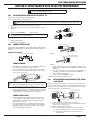
4.01 DIRECT PLUG MIG GUN INSTALLATION
Direct plug MIG guns install by directly inserting the rear connector plug into the feeder
wire guide outlet (see figure 2) and tightening the plug retaining screw. All models of MIG
guns, except the Euro-Kwik guns, require a control wire assembly to attach the MIG gun
trigger leads to the feeder. The control wire assemblies plug into the rear connector case
of the MIG gun, and into the control wire receptacle on the feeder. Euro-Kwik connections
are installed by inserting the gun connection into the feeder receptacle, aligning the
conduit plug first, then the gas plug. Push until all fittings are seated, then tighten the nut
hand tight as shown in figure 3.
Figure 2
Figure 3

SAFETY AND OPERATING INSTRUCTIONS
5 89200016
SECTION 5: SPRAY MASTER WITH VELOCITY2 MAINTENANCE
This section discusses servicing and or replacing various components of the Spray Master MIG Gun.
WARNING
Disconnect power from MIG Gun before servicing.
5.01 INSTALLING OR REPLACING VELOCITY2 CONTACT TIP
Avoid excessive consumables wear by periodically rotating tips.
Increase consumables life by occasionally rotating tips.
!
CAUTION
While nozzle and contact tip are removed, maintain an adequate distance of the wire from metal objects to avoid burnbacks to conduit or conductor tube.
1. (REPLACING) Remove worn nozzle and tip. (Clean nozzle if reusing.)
2. (NEW INSTALL) Slide new contact tip over the conduit end and into the conductor
tube end.
3. Replace the nozzle. Hand tighten (Nozzle secures tip).
NOTE!
For proper operation the nozzle MUST be tight.
4. Trim wire to desired stick out.
The MIG gun is now ready operation.
5.02 CONDUIT IDENTIFICATION
The procedure for removal and installation of a wire conduit is similar for all Tweco MIG guns.
Conduits may be identified by the type of conduit stop and the part number marking on each
conduit stop.
Example Part Number:
44-116-15
44 Series
1/16" (1,6mm) Wire Capacity
Liner length in feet
CONDUIT REMOVAL
1. Lay the MIG gun out on a table or on the floor in a straight line. Make sure the
gun is fully extended and all twists in the cable are removed.
2. Remove the nozzle and loosen the conduit set screw in the front of the gun.
This is usually located at the front of the handle. Then loosen the conduit set
screw in the rear connector plug.
Conduit set screw
NOTE!
On Miller® Direct Plug MIG guns, remove the nipple on the end of the connector
plug. On Euro-Kwik connections, remove the conduit retaining cap.
3. Remove the contact tip.
4. Grip the conduit stop and remove the conduit with a twisting motion. On Miller
®
Direct Plug MIG guns, twisting the rear of the gun approximately one revolution
clockwise will raise the conduit stop out of the connector plug recess.
CONDUIT INSTALLATION
1. Uncoil the conduit and lay it in a straight line. Insert the conduit into the rear
connector plug. Push the conduit into the gun with short strokes. If the conduit
hangs up, twist the conduit counterclockwise or gently whip the cable while
applying pressure to the conduit.
2. The conduit liner will need to be cut to length. This can be done by cutting
the conduit to match the one removed or inserting the new liner through the
MIG gun and trimming the conduit extending from the conductor tube to the
appropriate length using one of two methods.
Conductor end
Score on nozzle end
Nozzle
CUT
Method I
Conduit Trim Length
3/8”
(9 mm to 10 mm)
Conductor end
CUT
Method II
3. When the conduit is completely in the gun, tighten the rear conduit set screw.
On Miller
®
guns, reinstall the nipple. On Euro-Kwik® guns, reinstall the conduit
retaining cap.
4. Inspect the cut conduit end to remove burrs because they could interfere with
wire feeding or conflict with the conduit seating inside the VELOCITY2 tip.
Remove burrs with a file or side cutter.
5. Insert the contact tip and HAND tighten the nozzle.
The MIG gun is now ready to be reinstalled on the feeder.
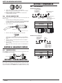
5.03 INSTALLING/REPLACING STAINLESS STEEL SLEEVE
/ LOCK COLLAR
Tweco offers replacement conductor tubes, refer to Section 8, that has a stainless steel
sleeve & lock collar on the end of the tube to accept the VELOCITY2 front end wear parts.
The Stainless Steel Sleeve is held in place by one screw (some models have two screws)
and the sleeve holds the lock collar assembly in place.
SCREW (SLEEVE)
Lock collar and wave spring are held
in place by the stainless steel sleeve.
STAINLESS STEEL SLEEVE
CONDUCTOR TUBE END
Tighten until screw head bottoms out.
1. Remove the front end consumables from the conductor tube.
2. Using a 5/64" Hex wrench remove the Sleeve Screw(s) and slide the Stainless
Steel Sleeve off the conductor tube end.
Notice that the Lock Collar assembly is now loose.
3. If the Lock Collar assembly is being replaced, remove the assembly now.
a) Clean conductor tube end and lock collar seat on the conductor tube.
b) Assemble the Lock Collar parts in this order and slide onto the
conductor tube end.

6
SAFETY AND OPERATING INSTRUCTIONS
89200016
Lock Collar
Spring Washer Snap Ring
4. Slide the Stainless Steel Sleeve onto the conductor tube end.
5. Align the set screw with the threaded hole in the conductor tube and tighten
until the screw bottoms out. Do not overtighten.
The conductor tube Stainless Steel Sleeve replacement is complete. Trim the
conduit and install the consumables.
5.04 REPLACE CONDUCTOR TUBE
The conductor tube is attached to the MIG Gun handle by two set screws on the side of the
handle. To remove:
1. Remove the front end consumables from the conductor tube.
Loosen the conduit liner set screw with a 5/64" hex wrench supplied and then
loosen the socket head cap screw securing the conductor tube in place inside
the handle with a 5/32" hex wrench. Refer to the figure below.
2. Remove conductor tube.
Conductor Tube set screw
Conduit Liner set screw
3. Mount the conductor tube O-ring on the end of the conductor tube.
Slide the tube over the liner and insert into the brass connection within the
handle. Tighten the socket head cap screw wrench tight using the 5/32" hex
wrench.
4. Tighten the conduit set screw down against the liner. Do not overtighten to
avoid damages the liner.
5. Check the length of conduit extending from the conductor tube front end and
adjust if necessary.
There are two methods of trimming the conduit. See "Conduit Installation" on
page 5.
SECTION 6: CABLEHOZ® REPAIR
6.01 CABLEHOZ® REPAIR
If you should find it necessary to repair Cablehoz connection(s), repair instructions can be
found at www.Tweco.com our website.
RED
WHITE
BLACK
BLACK
RED
WHITE
BLACK
BLACK
TRIGGER
NOT USED
NOT USED
BLUE
BROWN
CONTROL WIRE
CABLEHOZ
{
SECTION 7: TROUBLESHOOTING
Contact tips and nozzles should be cleaned frequently. Spatter buildup may cause bridging
between nozzle and tip. This could cause electrical shorting between the nozzle and work
piece as well as poor or improper gas flow. Regularly inspect the conductor tube, handle,
cable, and other parts of the MIG Gun for abrasion, cuts, or undue wear. Replace or repair
any parts found deficient. Refer to www.Tweco.com for MIG Gun troubleshooting chart(s).
SECTION 8: CONSUMABLES
8.01 TIPS AND NOZZLES
VELOCITY2 Nozzle Identification
VNM50FS
VELOCITY2
Nozzle
Blank=Standard Recess
F=Flush
2PC=Two Piece
R=Recess 1/4" (6.35 mm)
FAS=Spot Weld
FC=Flux Core
S= Small (Light Duty)
M=Medium Duty
H=Heavy Duty
ET=Extended Taper
Orifice Opening Size:
37=3/8” 62=5/8”
50=1/2” 75=3/4”
Blank= Fixed Threaded
S=Adjustable Slip
Nozzle Convention
2 Knurl Rings VNM
3 Knurl Rings VNH
4 Knurl Rings VNET
Medium Duty Heavy Duty
VELOCITY2 Contact Tip Identification
VTMA30
VELOCITY2
Tip
S= Small (Light Duty)
M=Medium Duty
H=Heavy Duty
ET=Extended Taper
A=Alum
Blank=Other
Wire Size: 364=3/64”
23=0.023” 116=1/16”
30=0.030” 564=5/64”
35=0.035” 332=3/32”
40=0.040” 764=7/64”
45=0.045” 18=1/8”
Contact Tip Convention
2 Rings VTM
3 Rings VTH
4 Rings VTET
Medium Duty Heavy Duty

SAFETY AND OPERATING INSTRUCTIONS
7 89200016
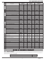
Medium Duty Contact Tips Heavy Duty Contact Tips Extended Taper Contact Tips
Description Part No. Stock No. Description Part No. Stock No. Description Part No. Stock No.
.023" (0.6 mm)
VTM23
1160-1750 .030" (0.8 mm)
VTH30
1160-1760 .030" (0.8 mm)
VTET30
1160-1772
.030" (0.8 mm)
VTM30
1160-1751 .035" (0.9 mm)
VTH35
1160-1761 .035" (0.9 mm)
VTET35
1160-1773
.035" (0.9 mm)
VTM35
1160-1752 .040" (1.0 mm)
VTH40
1160-1762 .040" (1.0 mm)
VTET40
1160-1774
.040" (1.0 mm)
VTM40
1160-1753 .045" (1.2 mm)
VTH45
1160-1763 .045" (1.2 mm)
VTET45
1160-1775
.045" (1.2 mm)
VTM45
1160-1754 3/64" (1.2 mm)*
VTHA364*
1160-1764 3/64" (1.2 mm)*
VTETA364*
1160-1776
3/64" (1.2 mm)*
VTMA364*
1160-1755 .052" (1.3 mm
)
VTH52
1160-1765 .052" (1.3 mm)
VTET52
1160-1777
.052" (1.3 mm)
VTM52
1160-1756 1/16" (1.6 mm)
VTH116
1160-1766 1/16" (1.6 mm)
VTET116
1160-1778
1/16" (1.6 mm)
VTM116
1160-1757 1/16" (1.6 mm)*
VTHA116*
1160-1767
Extended HD Taper Contact Tips
1/16" (1.6 mm)*
VTMA116*
1160-1758 5/64" (2.0 mm)
VTH564
1160-1768
5/64" (2.0 mm)
VTM564
1160-1759 3/32" (2.4 mm)
VTH332
1160-1769
Description Part No. Stock No.
7/64" (2.8 mm)
VTH764
1160-1770 .035" (0.9 mm)
VTHET35
1160-1780
* For Aluminum
1/8" (3.2 mm)
VTH18
1160-1771 .045" (1.2 mm)
VTHET45
1160-1782
.052" (1.3 mm)
VTHET52
1160-1784
1/16" (1.6 mm)
VTHET
116
1160-1785
Medium Duty Nozzles
Description Part No. Stock No.
1/2" (12.7 mm) Threaded Nozzle Recess
VNM50
1240-1857
1/2" (12.7 mm) Threaded Nozzle Flush
VNM50F
1240-1856
5/8" (15.9 mm) Threaded Nozzle Recess
VNM62
1240-1854
5/8" (15.9 mm) Threaded Nozzle Flush
VNM62F
1240-1855
3/4" (19.1 mm) Threaded Nozzle Recess
VNM75
1240-1852
3/4" (19.1 mm) Threaded Nozzle Flush
VNM75F
1240-1853
1/2" (12.7 mm) Slip Nozzle
VNM50S
1240-1859
5/8" (15.9 mm) Slip Nozzle
VNM62S
1240-1860
3/4" (19.1 mm) Slip Nozzle
VNM75S
1240-1863
Slip Nozzle Base
VNS
1240-1864
1/2" (12.7 mm) Slip Nozzle Cone Only
VNM50SC
1240-1861
5/8" (15.9 mm) Slip Nozzle Cone Only
VNM62SC
1240-1862
3/4" (19.1 mm) Slip Nozzle Cone Only
VNM75SC
1240-1865
Flux Core Nozzle
VNLFC
1240-1892
5/8" (15.9
mm) Spot Nozzle
VNM62FAS
1240-1866
3/4" (19.1 mm) Spot Nozzle
VNM75FAS
1240-1868
Extended Taper Nozzle
Extended Taper Nozzle
VNET37F
1240-1897
Heavy Duty Nozzles
Description Part No. Stock No.
5/8" (15.9 mm) Threaded Nozzle Recess
VNH62
1240-1877
5/8" (15.9 mm) Threaded Nozzle Flush
VNH62F
1240-1878
3/4" (19.1 mm) Threaded Nozzle Recess
VNH75
1240-1875
3/4" (19.1 mm) Threaded Nozzle Flush
VNH75F
1240-1876
5/8" (15.9 mm) Slip Nozzle
VNH62S
1240-1893
3/4" (19.1 mm) Slip Nozzle
VNH75S
1240-1894
Slip Nozzle Base
VNS
1240-1864
1/2” (12.7mm) 2 Piece Nozzle Cone Only Recess
VNH50RC
1240-1867
5/8" (15.9 mm) Slip Nozzle Cone Only
VNH62SC
1240-1895
3/4" (19.1 mm) Slip Nozzle Cone Only
VNH75SC
1240-1896
5/8" (15.9 mm) 2 Piece Nozzle Assembly Recess
VNH622PC
1240-1880
5/8" (15.9 mm) 2 Piece Nozzle Cone Only Recess
VNH62C
1240-1884
5/8" (15.9 mm) 2 Piece Nozzle Assembly Flush
VNH62F2PC
1240-1881
5/8" (15.9 mm) 2 Piece Nozzle Cone Only Flush
VNH62FC
1240-1885
3/4" (19.1 mm) 2 Piece Nozzle Assembly Recess
V
NH752PC
1240-1882
3/4" (19.1 mm) 2 Piece Nozzle Cone Only Recess
VNH75C
1240-1886
3/4" (19.1 mm) 2 Piece Nozzle Assembly Flush
VNH75F2PC
1240-1883
3/4" (19.1 mm) 2 Piece Nozzle Cone Only Flush
VNH75FC
1240-1887
Nozzle Retainer
VNH2PC
1240-1879
Flux Core Tip Holder & Insulator
VNSFC
1220-1207
Note: VELOCITY2 medium and heavy duty contact tips and nozzles are for use
with Tweco Classic
®
No. series and Spray Master
®
series MIG Guns.
Some parts may not be available at this time.
8.02 CONDUIT
250 AMP
Length
Wire Size
.035" - .045" (1,0mm - 1,2)mm
Part No. Stock No.
12 Ft
15 Ft
42-4045-15 1420-1123
20 Ft
25 Ft
42-4045-25 1420-1125
350 AND 450 AMP
Length
Wire Size
.052" - 1/16" (1,3mm - 1,6mm)
350 Amp 450 Amp
Part No. Stock No. Part No. Stock No.
10 Ft See 15 Ft See 15 Ft
12 Ft See 15 Ft See 15 Ft
15 Ft
44-116-15 1440-1113 44-116-15 1440-1113
20 Ft See 20 Ft See 20 Ft
25 Ft
44-116-25 1440-1115
8.03 CONDUCTOR TUBE
STANDARD REPLACEMENT CONDUCTOR TUBE
(250, 350, and 450 Amp)
Part Number Stock Number
SMVCTLS60 1240-1377
SMVCTLS45 1240-1376
SMVCTLS60LM 1640-1403
SMVCTLS45LM 1640-1402
OPTIONAL REPLACEMENT CONDUCTOR TUBE (WITH STAINLESS STEEL SLEEVE)
(250, 350, and 450 Amp)
Part Number Stock Number
SMVCT60SS 1240-1378
SMVCT45SS 1240-1379
SMVCT60LMSS 1640-1404
SMVCT45LMSS 1640-1405
SMVCT180 1240-1375

8
SAFETY AND OPERATING INSTRUCTIONS
89200016
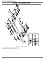
SECTION 9: REPLACEMENT PARTS
9b
9
1
21
10b
10c
6b
6d
4b
1a
4a
5
3
2b
2c
2a
2e
2d
10a
11
7b
8b
9b
8a
7a
9a
1b
1c
Refer to Section 8 for Nozzles and Contact Tips
Refer to 8.01 Tips and Nozzles for tip and nozzle part numbers and descriptions.
Refer to 8.02 Conduit for conduit part numbers and descriptions.
Refer to 8.03 Conductor Tube for conductor tube part numbers and descriptions.

SAFETY AND OPERATING INSTRUCTIONS
9 89200016
#Description
Spray Master
V250 Amp
Spray Master
V350 Amp
Spray Master
V450 Amp
Part No.Stock No.Part No.Stock No.Part No.Stock No.
1
Conductor Tube - 60°
SMVCTLS60
1240-1377
SMVCTLS60
1240-1377
SMVCTLS60
1240-1377
Conductor Tube - 45°
SMVCTLS45
1240-1376
SMVCTLS45
1240-1376
SMVCTLS45
1240-1376
Conductor Tube - 60° LM
SMVCTLS60LM
1640-1403
SMVCTLS60LM
1640-1403
SMVCTLS60LM
1640-1403
Conductor Tube - 45° LM
SMVCTL45LM
1640-1402
SMVCTL45LM
1640-1402
SMVCTL45LM
1640-1402
1a Silicone Tubing (Sold/Foot)
VCTLJBLK
1640-1409
VCTLJBLK
1640-1409
VCTLJBLK
1640-1409
1b Insulator, VELOCITY2 Conductor Tube Assy.
VCTLSI
1640-1408
VCTLSI
1640-1408
VCTLSI
1640-1408
1c O-Ring (Pkg. Of 10 each)
VCTLS015
1640-1410
VCTLS015
1640-1410
VCTLS015
1640-1410
2
Conductor Tube - 60° (Stainless Steel Sleeve)
SMVCT60SS
1240-1378
SMVCT60SS
1240-1378
SMVCT60SS
1240-1378
Conductor Tube - 45° (Stainless Steel Sleeve)
SMVCT45SS
1240-1379
SMVCT45SS
1240-1379
SMVCT45SS
1240-1379
Conductor Tube - 60° LM (Stainless Steel Sleeve)
SMVCT60LMSS
1640-1404
SMVCT60LMSS
1640-1404
SMVCT60LMSS
1640-1404
Conductor Tube - 45° LM (Stainless Steel Sleeve)
SMVCT45LMSS
1640-1405
SMVCT45LMSS
1640-1405
SMVCT45LMSS
1640-1405
Conductor Tube - 180° (Stainless Steel Sleeve)
SMVCT180
1240-1375
SMVCT180
1240-1375
SMVCT180
1240-1375
2a Threaded Stainless Sleeve
VCTLSL
1640-1397
VCTLSL
1640-1397
VCTLSL
1640-1397
2b Nozzle Collar
VCTLSLK
1640-1398
VCTLSLK
1640-1398
VCTLSLK
1640-1398
2c Wave Spring
VCTLSPR
1640-1399
VCTLSPR
1640-1399
VCTLSPR
1640-1399
2d Wave Spring Retainer
PMA64RS
1640-1396
PMA64RS
1640-1396
PMA64RS
1640-1396
2e Sleeve Screw
VCT41CS
2040-2048
VCT41CS
2040-2048
VCT41CS
2040-2048
3
Handle – Standard Spray Master
SMV82
2060-2082
SMV83
2060-2083
SMV84
2060-2084
Handle – Dual Schedule (Rocker Switch)
--
--
SMV83DS
2060-2077
SMV84DS
2060-2078
Handle – Locking Trigger
SMV82LC
2060-2079
SMV83LC
2060-2080
SMV84LC
2060-2081
4a
Trigger – Standard & Dual Schedule
ELC94
2060-2647
ELC94
2060-2647
ELC94
2060-2647
Trigger – Locking
MS94LC
2060-2693
MS94LC
2060-2693
MS94-LC
2060-2693
4b Dual Schedule Rocker Switch
--
--
MS94RSW
2060-2694
MS94-RSW
2060-2694
5Trigger Blade Assembly
ELC94-BL
2060-2671
ELC94BL
2060-2671
ELC94-BL
2060-2671
6a
Cablehoz
®
Assembly – 10 ft (3 m)
--
--
MS310
1730-2035
--
--
Cablehoz Assembly – 12 ft (4 m)
MS212
1720-2116
MS312
1730-2036
MS512
1750-2116
Cablehoz Assembly – 15 ft (5 m)
MS215
1720-2117
MS315
1730-2037
MS515
1750-2117
Cablehoz Assembly – 25 ft (8 m)
--
--
MS325
1730-2038
MS525
1750-2118
Cablehoz Assembly, Euro-Kwik – 12 ft (4 m)
--
--
--
--
MS512X
1750-2119
Cablehoz Assembly, Euro-Kwik – 15 ft (5 m)
MS215X
1720-2108
--
--
MS515X
1750-2120
Cablehoz Assembly, Euro-Kwik – 25 ft (8 m)
MS225X
1720-2109
--
--
--
--
6b
Cablehoz Front Mechanical Connector
Replacement Kit
MS102RK
2060-2132
MS104RK
2060-2133
MS104RK
2060-2133
6c
Cablehoz Rear Mechanical Connector
Replacement Kit
MS172RK
2060-2134
MS174RK
2060-2135
MS174RK
2060-2135
6d
Cablehoz Rear Mechanical Connector
Replacement Kit For Euro-Style
172XM
2020-2181
174XM
2040-2181
174XM
2040-2181
7a Miller
®
Rear Connector
350174MHFS
2035-2118
350174MHFS
2035-2118
350174MHFS
2035-2118
7b Miller Control Wire & Plug
WM354M
2030-2075
WM354M
2030-2075
WM354M
2030-2075
NS Miller Dual Schedule Control Wire & Plug
--
--
194DS
2040-2195
194DS
2040-2195
8a Tweco
®
Rear Connector
350174HFS
2035-2119
350174HFS
2035-2119
350174HFS
2035-2119
8b Tweco Control Wire
MS354TAJ
2060-2139
MS354TAJ
2060-2139
MS354TAJ
2060-2139
NS Tweco Dual Schedule Control Wire & Plug
MS354DSTJ
2060-2138
MS354DSTJ
2060-2138
MS354DSTJ
2060-2138
9a Lincoln
®
Rear Connector
350174LH
2035-2112
350174LH
2035-2112
350174LH
2035-2112
9b Lincoln Control Wire & Plug
MS354DSLJ
2060-2137
MS354DSLJ
2060-2137
MS354DSLJ
2060-2137
10a Euro-Kwik Connection Assembly
174EX1
2040-2276
174EX1
2040-2276
174EX1
2040-2276
10b Euro-Kwik Nut
174X2
2040-2177
174X2
2040-2177
174X2
2040-2177
10c Euro-Kwik Connector Case
X6RC
2060-2006
X6RC
2060-2006
X6RC
2060-2006
11 Conduit Refer to our full line catalog 64-2103 or visit tweco.com
SECTION 10: STATEMENT OF WARRANTY
10.01 WARRANTY SCHEDULE
The warranty is effective below for the time stated in the Warranty Schedule beginning on the date that the authorized distributor delivers the products to the purchaser. ESAB reserves
the right to request documented evidence of date of purchase.
MIG Torches and Arc Accessories Parts / Labor
All MIG Gun products 30 days from date purchaser purchases from seller. 30 days / NA

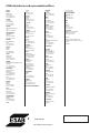
www.esab.eu
©2015 Welding and Cutting Products
Europe
AUSTRIA
ESAB Ges.m.b.H
Vienna-Liesing
Tel: +43 1 888 25 11
Fax: +43 1 888 25 11 85
BELGIUM
S.A. ESAB N.V.
Heist-op-den-Berg
Tel: +32 70 233 075
Fax: +32 15 257 944
BULGARIA
ESAB Kft Representative Oce
Soa
Tel/Fax: +359 2 974 42 88
THE CZECH REPUBLIC
ESAB VAMBERK s.r.o.
Vamberk
Tel: +420 2 819 40 885
Fax: +420 2 819 40 120
DENMARK
Aktieselskabet ESAB
Herlev
Tel: +45 36 30 01 11
Fax: +45 36 30 40 03
FINLAND
ESAB Oy
Helsinki
Tel: +358 9 547 761
Fax: +358 9 547 77 71
FRANCE
ESAB France S.A.
Cergy Pontoise
Tel: +33 1 30 75 55 00
Fax: +33 1 30 75 55 24
GERMANY
ESAB Welding & Cutting GmbHZweigstelle
Langenfeld
Tel.: +49 2173 3945 0
Fax.: +49 2173 3945 218
GREAT BRITAIN
ESAB Group (UK) Ltd
Waltham Cross
Tel: +44 1992 76 85 15
Fax: +44 1992 71 58 03
ESAB Automation Ltd
Andover
Tel: +44 1264 33 22 33
Fax: +44 1264 33 20 74
HUNGARY
ESAB Kft
Budapest
Tel: +36 1 20 44 182
Fax: +36 1 20 44 186
ITALY
ESAB Saldatura S.p.A.
Bareggio (Mi)
Tel: +39 02 97 96 8.1
Fax: +39 02 97 96 87 01
THE NETHERLANDS
ESAB Nederland B.V.
Amersfoort
Tel: +31 33 422 35 55
Fax: +31 33 422 35 44
NORWAY
AS ESAB
Larvik
Tel: +47 33 12 10 00
Fax: +47 33 11 52 03
POLAND
ESAB Sp.zo.o.
Katowice
Tel: +48 32 351 11 00
Fax: +48 32 351 11 20
PORTUGAL
ESAB Lda
Lisbon
Tel: +351 8 310 960
Fax: +351 1 859 1277
ROMANIA
ESAB Romania Trading SRL
Bucharest
Tel: +40 316 900 600
Fax: +40 316 900 601
RUSSIA
LLC ESAB
Moscow
Tel: +7 (495) 663 20 08
Fax: +7 (495) 663 20 09
SLOVAKIA
ESAB Slovakia s.r.o.
Bratislava
Tel: +421 7 44 88 24 26
Fax: +421 7 44 88 87 41
SPAIN
ESAB Ibérica S.A.
San Fernando de Henares
Tel: +34 91 878 3600
Fax: +34 91 802 3461
SWEDEN
ESAB Sverige AB
Gothenburg
Tel: +46 31 50 95 00
Fax: +46 31 50 92 22
ESAB international AB
Gothenburg
Tel: +46 31 50 90 00
Fax: +46 31 50 93 60
SWITZERLAND
ESAB AG
Baar
Tel.: +41 44 741 25 25
Fax.: +41 44 740 30 55
UKRAINE
ESAB Ukraine LLC
Kiev
Tel: +38 (044) 501 23 24
Fax: +38 (044) 575 21 88
North and South America
ARGENTINA
CONARCO
Buenos Aires
Tel: +54 11 4 753 4039
Fax: +54 11 4 753 6313
BRAZIL
ESAB S.A.
Contagem-MG
Tel: +55 31 2191 4333
Fax: +55 31 2191 4440
CANADA
ESAB Group Canada Inc.
Missisauga, Ontario
Tel: +1 905 670 02 20
Fax: +1 905 670 48 79
MEXICO
ESAB Mexico S.A.
Monterrey
Tel: +52 8 350 5959
Fax: +52 8 350 7554
USA
ESAB Welding & Cutting Products
Florence, SC
Tel: +1 843 669 44 11
Fax: +1 843 664 57 48
Asia/Pacic
AUSTRALIA
ESAB South Pacic
Archereld BC QLD 4108
Tel: +61 1300 372 228
Fax: +61 7 3711 2328
CHINA
Shanghai ESAB A/P
Shanghai
Tel: +86 21 2326 3000
Fax: +86 21 6566 6622
INDIA
ESAB India Ltd
Calcutta
Tel: +91 33 478 45 17
Fax: +91 33 468 18 80
INDONESIA
P.T. ESABindo Pratama
Jakarta
Tel: +62 21 460 0188
Fax: +62 21 461 2929
JAPAN
ESAB Japan
Tokyo
Tel: +81 45 670 7073
Fax: +81 45 670 7001
MALAYSIA
ESAB (Malaysia) Snd Bhd
USJ
Tel: +603 8023 7835
Fax: +603 8023 0225
SINGAPORE
ESAB Asia/Pacic Pte Ltd
Singapore
Tel: +65 6861 43 22
Fax: +65 6861 31 95
SOUTH KOREA
ESAB SeAH Corporation
Kyungnam
Tel: +82 55 269 8170
Fax: +82 55 289 8864
UNITED ARAB EMIRATES
ESAB Middle East FZE
Dubai
Tel: +971 4 887 21 11
Fax: +971 4 887 22 63
Africa
EGYPT
ESAB Egypt
Dokki-Cairo
Tel: +20 2 390 96 69
Fax: +20 2 393 32 13
SOUTH AFRICA
ESAB Africa Welding & Cutting Ltd
Durbanvill 7570 - Cape Town
Tel: +27 (0)21 975 8924
Distributors
For addresses and phone numbers to our
distributors in other countries, please visit our
home page
www.esab.eu
ESAB subsidiaries and representative oces
-
 1
1
-
 2
2
-
 3
3
-
 4
4
-
 5
5
-
 6
6
-
 7
7
-
 8
8
-
 9
9
-
 10
10
-
 11
11
-
 12
12


ESAB Tweco Spray Master MIG Guns with VELOCITY2 Manuel utilisateur
- Taper
- Manuel utilisateur
- Ce manuel convient également à
dans d''autres langues
Documents connexes
-
Tweco Tweco Spray Master MIG Guns with VELOCITY2 Manuel utilisateur
-
-
 Tweco Classic No. Series Mig Guns Manuel utilisateur
-
 Tweco Classic No. Series Mig Guns Manuel utilisateur
-
 Tweco Classic Serial No. Mig Guns Manuel utilisateur
-
 Tweco Classic No. Series Mig Guns Manuel utilisateur
-
 Tweco Classic No. Series Mig Guns with Velocity Consumables Manuel utilisateur
-
 Tweco Classic Serial No. Mig Guns Manuel utilisateur
-
-
 Tweco Robotics QFA600 QFW600 Quick Fixed Automation Direct Plug Torches Guide d'installation


