
OWNER’S MANUAL OM-274911A
2016−04
For SubArc Tandem Mounting Bracket (301135)
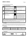
1. Safety Symbol Definitions
DANGER! − Indicates a hazardous situation which, if not
avoided, will result in death or serious injury. The possible
hazards are shown in the adjoining symbols or explained in
the text.
DANGER ! - Indique une situation dangereuse qui, si elle
n’est pas évitée, entraînera la mort ou des blessures graves.
Les éventuels risques sont représentés par les symboles
joints ou expliqués dans le texte.
Fsafe1 2013-10
Beware of electric shock from wiring. Disconnect input pow-
er before installing this kit. Reinstall all panels and covers.
Attention aux décharges électriques au contact des câbles.
Couper l’alimentation électrique avant d’installer ce kit. Ré-
installer tous les panneaux et couvercles.
Fsafe7 2013-10
Indicates a hazardous situation which, if not avoided, could
result in death or serious injury. The possible hazards are
shown in the adjoining symbols or explained in the text.
Indique une situation dangereuse qui, si elle n’est pas évitée,
entraînera la mort ou des blessures graves. Les éventuels
risques sont représentés par les symboles joints ou exp-
liqués dans le texte.
Fsafe2 2013-10
Wear safety glasses with side shields.
Porter des lunettes de sécurité avec écrans latéraux.
Fsafe8 2013-10
NOTICE
Indicates statements not related to personal injury.
Signale des consignes non associées aux dommages cor-
porels.
Indicates special instructions.
Fournit des instructions spéciales.
Fsafe3 2013-10
Have only trained and qualified persons install, operate, or
service this unit. Read the safety information at the begin-
ning of these instructions and in each section. Call your dis-
tributor if you do not understand the directions. For WELD-
ING SAFETY and EMF information, read owner’s manual(s).
Ne confiez l’installation, l’exploitation ou l’entretien de cet
appareil qu’à des personnes compétentes et qualifiées. Lire
les directives de sécurité au début de ces instructions et
dans chaque section. Appeler votre distributeur si vous
ne comprenez pas les directives. Lire le(s) manuel(s)
d’utilisateur pour des renseignements sur la SÉCURITÉ
DE SOUDAGE et les champs électromagnétiques.
Fsafe15 2013-10
CALIFORNIA PROPOSITION 65 WARNINGS
Welding or cutting equipment produces fumes or gases which contain chemicals known to the State of California to cause birth defects and, in some
cases, cancer. (California Health & Safety Code Section 25249.5 et seq.) This product contains chemicals, including lead, known to the state of Cali-
fornia to cause cancer, birth defects, or other reproductive harm. Wash hands after use.
Les équipements de soudage et de coupage produisent des fumées et des gaz qui contiennent des produits chimiques dont l’État de Californie recon-
naît qu’ils provoquent des malformations congénitales et, dans certains cas, des cancers. (Code de santé et de sécurité de Californie, chapitre
25249.5 et suivants) Ce produit contient des produits chimiques, notamment du plomb, dont l’État de Californie reconnaît qu’ils provoquent des
cancers, des malformations congénitales ou d’autres problèmes de procréation. Se laver les mains après utilisation.
Fsafe4 2013-10
2. Description
The tandem mounting bracket is designed to provide support for Miller®SubArc welding equipment or other welding equipment. The mounting bracket
is intended to provide support for the Miller Flux Hopper and wire drive system. This unit can either be mounted on a fixed arm or movable slide.
Contact the manufacturer of the fixed arm or movable slide to ensure it is capable of supporting the weight of the tandem bracket and
attached equipment.
3. Specifications
Product Type Overall Dimensions Weight
Tandem Mounting Bracket 27.50 in. X 8.50 in. X 16.25 in.
(699 mm x 216 mm x 413 mm)
92 lbs
(41.7 kg)
4. Tools Needed
5/16 in.
7/16, 9/16 in.

OM-274911 Page 2
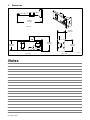
5. Dimensions
275343-A
Top view
27.500 in.
(699 mm)
8.500 in.
(216 mm)
12.500 in.
(318 mm)
Back View
Side View
16.250 in.
(413 mm)
11.000 in.
(279 mm)
Notes

OM-274911 Page 3
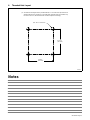
6. Threaded Hole Layout
. The tandem mounting bracket is provided with 3/8 x 1.75 socket head cap hardware for
attaching the bracket to a fixed arm or movable slide. If desired, M10 x 45 hardware may
be used. In this case, the threaded holes should be adjusted accordingly.
275344-A
3/8 - 16 x 1.75 4 Places
5.375 in.
(137 mm)
5.375 in.
(137 mm)
Notes

OM-274911 Page 4
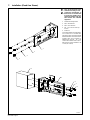
7. Installation (Fixed Arm Shown)
Turn Off all electrical equip-
ment before working on unit.
Contact the manufacturer of
the fixed arm or movable slide
to ensure it is capable of sup-
porting the weight of the tan-
dem bracket and attached
equipment.
1 Tandem Mounting Bracket
2 3/8 In. Flat Washers
3 3/8 In. Lock Washers
4 3/8 - 16 x 1.75 SOC HD Cap
Screws
5 Fixed Arm
To mount the tandem mounting brack-
et to a fixed arm or movable slide,
align the four holes on the bracket with
the threaded holes on the fixed arm or
movable slide. Secure bracket by
tightening the four 3/8 - 16 x 1.75
screws and hardware with a 5/16 in.
Allen wrench. Torque hardware to 30
± 2 ft-lb (40 ± 3 N⋅M).
275346-A
1
2
3
4
5
1
2
3
4

OM-274911 Page 5
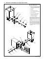
8. Mounting A Flux Hopper (Flux Hopper Not Included)
Turn Off all electrical equipment
before working on unit.
. Secure tandem mounting bracket to
fixed arm or movable slide (see Sec
-
tion 7) before mounting flux hopper.
1 Flux Hopper
2 Insulator
3 Mounting Plate, Flux Hopper
4 1/4 in. Insulating Shoulder Washers
5 1/4 in. Flat Washers
6 1/4 − 20 x .75 in. Bolts (Supplied
w/Tandem Mounting Bracket)
7 Tandem Mounting Bracket
8 1/4 − 20 x 1.00 in. Bolts
Before installing the flux hopper, remove
hardware (items 2−6), and discard flux
hopper mounting plate and the 1/4 - 20 x
.75 in. bolts. Retain insulator and other
hardware.
Place existing insulator between flux
hopper and tandem mounting bracket
.
Align holes, and secure flux hopper to
tandem mounting bracket with supplied
1/4 - 20 x 1.00 in. bolts and existing hard-
ware. Torque hardware to 7.5 ± 1 ft-lb (10
± 1.5 N⋅M).
275347-A
1
2
3
4
5
6
1
2
7
4
5
8

OM-274911 Page 6
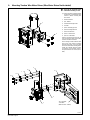
9. Mounting Tandem Wire Motor Drives (Wire Motor Drives Not Included)
Turn Off all electrical equip-
ment before working on unit.
. Secure tandem mounting bracket
to fixed arm or movable slide (see
Section 7) before mounting wire
drive motor.
1 Wire Drive Motor
2 3/8 - 16 Nuts
3 Tandem Mounting Bracket
4 Insulator
5 3/8 in. Insulating Spacers
6 3/8 in Insulating Washers
7 3/8 in. Flat Washers
8 3/8 in. Lock Washers
9 3/8 -16 x 1.250 Bolts
Remove and discard the four 3/8 -16
nuts from the wire drive motor. Retain
insulator and other hardware.
Place existing insulator between wire
drive motor and tandem mounting
bracket. Align holes, and secure wire
drive motor to tandem mounting brack-
et with 3/8 - 16 bolts, washers, insulat-
ing washers and insulating spacers.
Torque hardware to 30 ± 2 ft-lb (40 ± 3
N⋅M).
275348-A
1
2
3/8 - Threaded
T-Slot Nuts
(Miller Part No. 275345)
9
8
7
6
5
4
1
3

OM-274911 Page 7
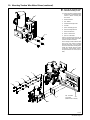
10. Mounting Tandem Wire Motor Drives (continued)
Turn Off all electrical equip-
ment before working on unit.
. Secure tandem mounting bracket
to fixed arm or movable slide (see
Section 7) before mounting wire
drive motor.
1 Wire Drive Motor
2 3/8 - 16 Nuts
3 Tandem Mounting Bracket
4 Insulator
5 3/8 in. Insulating Spacers
6 3/8 in Insulating Washers
7 3/8 in. Flat Washers
8 3/8 in. Lock Washers
9 3/8 -16 x 1.250 Bolts
Remove and discard the four 3/8 -16
nuts from the wire drive motor. Retain
insulator and other hardware.
Place existing insulator between wire
drive motor and tandem mounting
bracket. Align holes, and secure wire
drive motor to tandem mounting brack-
et with 3/8 - 16 bolts, washers, insulat-
ing washers, and insulating spacers.
Torque hardware to 30 ± 2 ft-lb (40 ± 3
N⋅M).
275349-A
1
2
3/8 - Threaded
T-Slot Nuts
(Miller Part No. 275345)
9
8
7
6
5
1
4
3

OM-274911 Page 8
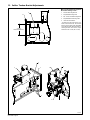
11. SubArc Tandem Bracket Adjustments
Turn Off all electrical equipment
before working on unit.
1 Tandem Mounting Bracket
2 Adjustable Mounting Plate
3 3/8 - 16 Hex Head Mounting Bolts
4 Adjustable Mount Backing Plate
5 Inner Wire Drive Motor
To adjust inner wire drive motor up or
down, loosen the four 3/8 - 16 hex head
bolts on the wire drive motor adjustable
mount backing plate. When finished po-
sitioning the wire drive motor, torque
hardware to 30 ± 2 ft-lb (40 ± 3 N⋅M).
275351-A
2.500 in.
Vertical Adjustment
1
2
1
4
5
3
1
2
5

OM-274911 Page 9
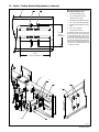
12. SubArc Tandem Bracket Adjustments (continued)
Turn Off all electrical equipment
before working on unit.
1 Tandem Mounting Bracket
2 3/8 - 16 Threaded T-Slot Nut
(Miller Part No. 275345)
3 Adjustable Slotted Mounting Plate
4 3/8 - 16 Hex Head Mounting Bolts
5 Adjustable Slotted Mount Backing
Plate
6 3/8 - 16 x 1.250 Bolts
7 Outer Wire Drive Motor
To adjust wire drive motor right or left,
loosen the four 3/8 - 16 hex head bolts
on outer wire drive motor mount. To ad-
just wire drive motor up or down, loosen
the four 3/8 - 16 hex head bolts securing
the slotted mounting plate to the tandem
bracket. When finished positioning the
wire drive motor, torque hardware to 30
± 2 ft-lb (40 ± 3 N⋅M).
275350-A
2.500 in.
Vertical
Adjustment
7.500 in.
Horizontal Adjustment
1
23
1
6
3
7
5
4

OM-274911 Page 10
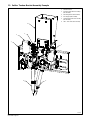
13. SubArc Tandem Bracket Assembly Example
1 Tandem Bracket
2 Inner Wire Drive Motor Assembly
(Not Included)
3 Wire Straightener (Not Included)
4 Flux Hopper (Not Included)
5 Outer Wire Drive Motor Assembly
(Not Included)
6 OBT - 1200 Torch (Not Included)
275352-A
6
6
5
1
2
3
4
3

OM-274911 Page 11
14. Replacement Parts List
DescriptionPart No.
Item
No.
1 275345 Nut, T-Slot 3/8 - 16.................. ......
Use only Manufacturer’s Suggested Replacement Parts. Model number required when ordering parts.
Notes

OM-274911 Page 12
Notes
-
 1
1
-
 2
2
-
 3
3
-
 4
4
-
 5
5
-
 6
6
-
 7
7
-
 8
8
-
 9
9
-
 10
10
-
 11
11
-
 12
12


Miller SUBARC TANDEM MOUNTING BRACKET Le manuel du propriétaire
- Taper
- Le manuel du propriétaire
- Ce manuel convient également à
dans d''autres langues
Documents connexes
-
Miller SINGLE MOUNTING BRACKET Le manuel du propriétaire
-
-
-
-
-
-
-
-
-