
Ki|chen_kid _
INSTALLATION INSTRUCTIONS
30" (76.2 CM) FREESTANDING AND SLIDE-IN
ELECTRIC RANGES
INSTRUCTIONS D'INSTALLATION DE
CUISINII_RES l_LECTRIQUES AUTOPORTANTES
ET COULISSANTES DE 30" (76,2 CM)
Table of Contents/Table des matieres ............................................................................. 2
iMPORTANT:
Save for local electrical inspector's use.
iMPORTANT:
,&,conserver pour consultation par I'inspecteur local des installations 61ectriques.
W10440541A

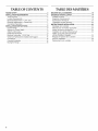
TABLEOF CONTENTS
RAN GE SAFETY ............................................................................. 3
INSTALLATION REQUIREMENTS ................................................ 4
Tools and Parts ............................................................................ 4
Location Requirements ................................................................ 4
Electrical Requirements - U.S.A. Only ......................................... 6
Electrical Requirements - Canada Only ....................................... 7
Countertop Preparation ............................................................... 8
INSTALLATION INSTRUCTIONS .................................................. 8
Unpack Range .............................................................................. 8
Measure for Proper Height ........................................................... 8
Adjust Leveling Legs .................................................................... 9
Install Anti-Tip Bracket ................................................................. 9
Electrical Connection - U.S.A. Only ........................................... 10
Verify Anti-Tip Bracket Is Installed and Engaged ...................... 15
Level Range ................................................................................ 16
Complete Installation ................................................................. 16
Moving the Range ...................................................................... 16
TABLEDES MATIERES
SI_CURITI_ DE LA CUISINIERE ................................................... 18
EXIGENCES D'INSTALLATION ................................................... 19
Outillage et pieces ...................................................................... 19
Exigences d'emplacement ......................................................... 19
Specifications electriques .......................................................... 22
Preparation du plan de travail ................................................... 22
INSTRUCTIONS D'INSTALLATION ............................................. 23
Deballage de la cuisiniere .......................................................... 23
Mesures pour une hauteur appropriee ...................................... 23
Ajuster les pieds de nivellement ................................................. 24
Installation de la bride antibasculement .................................... 24
Verifier que la bride anti-basculement
est bien installee et engagee ...................................................... 25
Reglage de I'aplomb de la cuisiniere ......................................... 25
Achever I'installation .................................................................. 26
Deplacement de la cuisiniere ..................................................... 26
2

RANGE SAFETY
Your safety and the safety of others are very important.
We have provided many important safety messages in this manual and on your appliance. Always read and obey all safety
messages.
This is the safety alert symbol.
This symbol alerts you to potential hazards that can kill or hurt you and others.
All safety messages will follow the safety alert symbol and either the word "DANGER" or "WARNING."
These words mean:
You can be killed or seriously injured if you don't immediately
follow instructions.
You can be killed or seriously injured if you don't follow
instructions.
All safety messages will tell you what the potential hazard is, tell you how to reduce the chance of injury, and tell you what can
happen if the instructions are not followed.
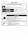
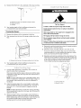
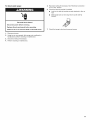
Anti-Tip
Bracket
Range Foot
Tip Over Hazard
A child or adult can tip the range and be killed.
Install anti-tip bracket to floor or wall per installation instructions.
Slide range back so rear range foot is engaged in the slot of the anti-tip bracket.
Re-engage anti-tip bracket if range is moved.
Do not operate range without anti-tip bracket installed and engaged.
Failure to follow these instructions can result in death or serious burns to children and adults.
To verify the anti-tip bracket is installed and engaged:
• Slide range forward.
• Look for the anti-tip bracket securely attached to floor or wall.
• Slide range back so rear range foot is under anti-tip bracket.
• See installation instructions for details.

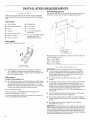
INSTALLATION REQUIREMENTS
Gather the required tools and parts before starting installation.
Read and follow the instructions provided with any tools listed
here.
Tools needed
• Tape measure •
• Flat-blade screwdriver •
• Level •
• Hammer •
• Hand or electric drill
• Wrench or pliers •
• Marker or pencil
Masking tape
1¼,nut driver
5/16"nut driver
1/8"(3.2 mm) drill bit (for
wood floors)
3/16"(4.8 mm) carbide-tipped
masonry drill bit (for
concrete/ceramic floors)
Parts supplied
Check that all parts are included.
Rear Filler Strip (optional)
The rear filler strip may be used to fill a gap between the rear of
the slide-in cooktop and the wall in a freestanding cutout.
A
B
B
g
!
A. Anti-tip bracket
B. #12 x 1%" screws
Anti-tip bracket must be securely mounted to subfloor or
wall. Thickness of flooring may require longer screws to
anchor bracket to subfloor. Longer screws are available from
your local hardware store.
Parts needed
If using a power supply cord:
• A UL listed power supply cord kit marked for use with ranges.
The cord should be rated at 250 volts minimum, 40 amps or
50 amps that is marked for use with nominal 13/8"(3.5 cm)
diameter connection opening and must end in ring terminals
or open-end spade terminals with upturned ends.
• A UL listed strain relief.
Check local codes. Check existing electrical supply. See
"Electrical Requirements" section.
It is recommended that all electrical connections be made by a
licensed, qualified electrical installer.
A. Rear filler strip
B. Countertop
C. Countertop cutout
Please reference the "Assistance or Service" section of the Use
and Care Guide to order.
Black - W10113902A
White - W10113903A
Biscuit - W10113904A
IMPORTANT: Observe all governing codes and ordinances.
• It is the installer's responsibility to comply with installation
clearances specified on the model/serial rating plate. The
model/serial rating plate is located inside the oven door on
the right-hand side oven door trim.
• The range should be located for convenient use in the
kitchen.
To eliminate the risk of burns or fire by reaching over heated
surface units, cabinet storage space located above the
surface units should be avoided. If cabinet storage is to be
provided, the risk can be reduced by installing a range hood
or microwave range hood combination that projects
horizontally a minimum of 5" (12.7 cm) beyond the bottom of
the cabinets.
• Cabinet opening dimensions that are shown must be used.
Given dimensions are minimum clearances.
• The anti-tip bracket must be installed. To install the anti-tip
bracket shipped with the range, see "Install Anti-Tip Bracket"
section.
• Grounded electrical supply is required. See "Electrical
Requirements" section.
IMPORTANT: To avoid damage to your cabinets, check with your
builder or cabinet supplier to make sure that the materials used
will not discolor, delaminate or sustain other damage. This oven
has been designed in accordance with the requirements of UL
and CSA International and complies with the maximum allowable
wood cabinet temperatures of 194°F (90°C).

Mobile Home - Additional Installation Requirements
The installation of this range must conform to the Manufactured
Home Construction and Safety Standard, Title 24 CFR, Part 3280
(formerly the Federal Standard for Mobile Home Construction
and Safety, Title 24, HUD Part 280). When such standard is not
applicable, use the Standard for Manufactured Home
Installations, ANSI A225.1/NFPA 501A or follow local codes.
In Canada, the installation of this range must conform with the
current standards CAN/CSA-A240-1atest edition or local codes.
Mobile home installations require:
• When this range is installed in a mobile home, it must be
secured to the floor during transit. Any method of securing
the range is adequate as long as it conforms to the standards
listed above.
• Four-wire power supply cord or cable must be used in a
mobile home installation. The appliance wiring will need to be
revised. See "Electrical Connection" section.
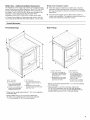
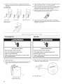
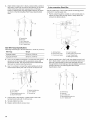
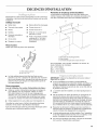
Product Dimensions
Freestanding Range Slide-in Range
A
B
E
A. 53/4'' (14.6 cm)
B. 30" (76.2 cm)
C. 413/4'' (106.0 cm) overall
height with leveling legs
screwed all the way in*
D. 36" (91.4 cm) cooktop trim
height with leveling legs
screwed all the way in*
E. 30" (76.2 cm)
F. 271/4''(69.2 cm) max. from
handle to standoff at back of
range**
G. Model/serial number plate
(located on the right-hand side
oven door trim)
*Range can be raised approximately 1" (2.5 cm) by adjusting
the leveling legs.
**When installed in a 24" (61.0 cm) base cabinet with
25" (63.5 cm) countertop; front of oven door protrudes
1" (2.5 cm) beyond 24" (61.0 cm) base cabinet.
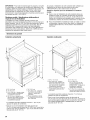
\ \ / l
-- ...... - .- \
A. 3011A6'' (77.6 cm)
B. 35%" (90.5 cm) height to
underside of cooktop edge
with levering legs screwed
all the way in*
C. Model/serial number plate
(located on the right-hand
side oven door trim)
D. 30" (76.2 cm)
E. 27_ " (69.2 cm)
(271¼_,,[70.3 cm] on
models KERS807XSP
and KESS907XSP) from
handle to standoff at
back of range**
F. 23" (58.4 cm) countertop
notch to rear of cooktop
*Range can be raised approximately 1" (2.5 cm) by adjusting
the leveling legs.
**When installed in a 24" (61.0 cm) base cabinet with
25" (63.5 cm) countertop; front of oven door protrudes
13/4'' (4.4 cm) (23/le'' [5.5 cm] on models KERS807XSP and
KESS907XSP) beyond 24" (61.0 cm) base cabinet.

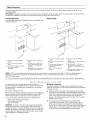
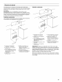
Cabinet Dimensions
Cabinet opening dimensions shown are for 25" (64.0 cm) countertop depth, 24" (61.0 cm) base cabinet depth and 36" (91.4 cm)
countertop height.
IMPORTANT: If installing a range hood or microwave hood combination above the range, follow the range hood or microwave hood
combination installation instructions for dimensional clearances above the cooktop surface.
Freestanding Range
A freestanding range may be installed next to combustible walls
with zero clearance.
Slide-in Range
E
I
I
G
H
E
A. 13" (33.0 cm) upper cabinet
depth
B. 30" (76.2 cm) min. opening
width
C. For minimum clearance to the
top of the cooktop,
see NOTE*.
D. 30" (76.2 cm) min. opening
width
E.Junction box - 8" (20.3 cm)
to 22" (55.9 cm) from either
cabinet, 7" (17.8 cm) max.
from floor
F. Cabinet door or hinge should
not extend into the cutout.
A. 13" (33.0 cm) upper cabinet
depth
B. 30" (76.2 cm) min. opening
width
C. For minimum clearance to
the top of the cooktop,
see NOTE*.
D. 22s/4'' (57.8 cm) opening
depth
E.30" (76.2 cm) min. opening
width
F. Square cut or 1/4"(6.2 cm) radius
both corners
G. Junction box - 8" (20.3 cm) to
22" (55.9 cm) from either
cabinet, 7" (17.8 cm) max. from
floor
H. Cabinet door or hinge should
not extend into cutout.
NOTE: 24" (61.0 cm) minimum when bottom of wood or metal cabinet is covered by not less than 1/4"(0.64 cm) flame retardant
millboard covered with not less than No. 28 MSG sheet steel, 0.015" (0.4 mm) stainless steel, 0.024" (0.6 mm) aluminum or
0.020" (0.5 mm) copper.
30" (76.2 cm) minimum clearance between the top of the cooking platform and the bottom of an uncovered wood or metal cabinet.
If codes permit and a separate ground wire is used, it is
recommended that a qualified electrical installer determine that
the ground path is adequate and wire gauge is in accordance
with local codes.
Do not use an extension cord.
Be sure that the electrical connection and wire size are adequate
and in conformance with the National Electrical Code, ANSI/
NFPA 70-latest edition and all local codes and ordinances.
A copy of the above code standards can be obtained from:
National Fire Protection Association
One Batterymarch Park
Quincy, MA 02269
WARNING: Improper connection of the equipment-grounding
conductor can result in a risk of electric shock. Check with a
qualified electrician or service technician if you are in doubt as to
whether the appliance is properly grounded. Do not modify the
power supply cord plug. If it will not fit the outlet, have a proper
outlet installed by a qualified electrician.
Electrical Connection
To properly install your range, you must determine the type of
electrical connection you will be using and follow the instructions
provided for it here.
• Range must be connected to the proper electrical voltage
and frequency as specified on the model/serial number rating
plate. The model/serial rating plate is located inside the oven
door on the right-hand side oven door trim. Refer to the
figures in the "Product Dimensions" section of the "Location
Requirements" section.
• This range is manufactured with the neutral terminal
connected to the cabinet. Use a 3-wire UL listed, 40- or
50-amp power supply cord (pigtail) (see following Range
Rating chart). If local codes do not permit ground through the
neutral, use a 4-wire power supply cord rated at 250 volts,
40 or 50 amps and investigated for use with ranges.
6

Range Rating* Specified Rating of
Power Supply Cord Kit
and Circuit Protection
120/240 Volts 120/208 Volts Amps
8.8 - 16.5 KW 7.8 - 12.5 KW 40 or 50**
16.6 - 22.5 KW 12.6 - 18.5 KW 50
*The NEC calculated load is less than the total connected load
listed on the model/serial rating plate.
**If connecting to a 50-amp circuit, use a50-amp rated cord with
kit. For 50-amp rated cord kits, use kits that specify use with a
nominal 13/8"(34.93 mm) diameter connection opening.
A circuit breaker is recommended.
The range can be connected directly to the fused disconnect
(or circuit breaker box) through flexible or nonmetallic
sheathed, copper or aluminum cable. See the "Electrical
Connection" section.
• Allow 2 to 3 ft (61.0 cm to 91.4 cm) of slack in the line so that
the range can be moved if servicing is ever necessary.
• A UL listed conduit connector must be provided at each end
of the power supply cable (at the range and at the junction
box).
• Wire sizes and connections must conform with the rating of
the range (40 amps).
• The wiring diagram is located on the underside of the storage
drawer or below the warming drawer in a clear plastic bag.
If connecting to a 4-wire system:
This range ismanufactured with the ground connected to the
cabinet. The ground must be revised so the green ground wire of
the 4-wire power supply cord is connected to the cabinet. See
the "Electrical Connection" section.
Grounding through the neutral conductor is prohibited for new
branch-circuit installations (1996 NEC); mobile homes; and
recreational vehicles, or an area where local codes prohibit
grounding through the neutral conductor.
When a 4-wire receptacle of NEMA Type 14-50R is used, a
matching UL listed, 4-wire, 250-volt, 40-amp, range power
supply cord (pigtail) must be used. This cord contains 4 copper
conductors with ring terminals or open-end spade terminals with
upturned ends, terminating in a NEMA Type 14-50P plug on the
supply end.
The fourth (grounding) conductor must be identified by a green or
green/yellow cover and the neutral conductor by a white cover.
Cord should be Type SRD or SRDT with a UL listed strain relief
and be at least 4 ft (1.22 m) long.
4-wire receptacle (14-50R)
The minimum conductor sized for the copper 4-wire power
cord are:
40-amp circuit
2 No.-8 conductors
1 No.-10 white neutral
1 No.-8 green grounding
If connecting to a 3-wire system:
Local codes may permit the use of a UL listed, 3-wire,
250 volt, 40-amp range power supply cord (pigtail). This cord
contains 3 copper conductors with ring terminals or open-end
spade terminals with upturned ends, terminating in a NEMA Type
10-50P plug on the supply end. Connectors on the appliance end
must be provided at the point the power supply cord enters the
appliance. This uses a 3-wire receptacle of NEMA Type 10-50R.
3-wire receptacle (10-50R)
Electrical Shock Hazard
Electrically ground range.
Failure to do so can result in death, fire, or
electrical shock.
If codes permit and a separate ground wire is used, it is
recommended that a qualified electrical installer determine that
the ground path is adequate and wire gauge are in accordance
with local codes.
Be sure that the electrical connection and wire size are adequate
and in conformance with CSA Standard C22.1, Canadian
Electrical Code, Part 1 - latest edition, and all local codes and
ordinances.
A copy of the above code standards can be obtained from:
Canadian Standards Association
178 Rexdale Blvd.
Toronto, ON M9W 1R3 CANADA
• Check with a qualified electrical installer if you are not sure
the range is properly grounded.
Range Rating* Specified Rating of
Power Supply Cord Kit
and Circuit Protection
120/240 Volts 120/208 Volts Amps
8.8 - 16.5 KW 7.8- 12.5 KW 40 or 50
16.6 - 22.5 KW 12.6 - 18.5 KW 50
*The NEC calculated load is less than the total connected load
listed on the model/serial/rating plate.
**If connecting to a 50-amp circuit, use a50-amp rated cord with
kit. For 50-amp rated cord kits, use kits that specify use with a
nominal 13/8"(34.9 mm) diameter connection opening.
• A time-delay fuse or circuit breaker is recommended.

ThisrangeisequippedwithaCSAInternationalCertified
PowerCordintendedtobepluggedintoastandard14-50R
wallreceptacle.Besurethewallreceptacleiswithinreachof
range'sfinallocation.
• Donotuseanextensioncord.
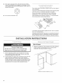
Thecooktopsidesoftheslide-inrangefitoverthecutoutedgeof
yourcountertop.
Ifyouhaveasquarefinish(flat)countertopandtheopeningwidth
is30"(76.2cm),nocountertoppreparationisrequired.
Formedfront-edgedcountertopsmusthavemoldededge
shavedflat3/8"(1.0cm)fromeachfrontcornerofopening.
Tilecountertopsmayneedtrimcutback%"(1.0cm)fromeach
frontcornerand/orroundededgeflattened.
30"
(76.2 crn)
(10era)
303A ''
(78.1 cm)
If countertop opening width is greater than 30" (76.2 cm), adjust
the %" (1.0 cm) dimension.
Countertop must be level. Place level on countertop, first side to
side, then front to back. If countertop is not level, range will not
be level. Range must be level for satisfactory baking conditions.
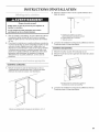
INSTALLATION INSTRUCTIONS
Excessive Weight Hazard
Use two or more people to move and install range.
Failure to do so can result in back or other injury.
1.
2.
Remove shipping materials, tape and film from the range.
Keep cardboard bottom under range. Remove oven racks
and parts package from inside oven.
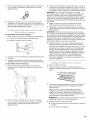
To place range on its back, take 4 cardboard corners from the
carton. Stack one cardboard corner on top of another.
Repeat with the other 2 corners. Place them lengthwise on
the floor behind the range to support the range when it is laid
on its back. Using 2 or more people, firmly grasp the range
and gently lay it on its back on the cardboard corners.
...........;:t_.......
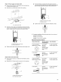
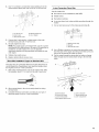
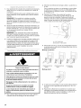
Slide-In Ranges:
1. Measure the distance of the countertop to the floor. Measure
at all 4 locations corresponding to the 4 corners of the
underside of the range cooktop, as shown.
A
Measure at locations marked A, B, C, D.
8

2. Measure from the floor to the underside of the range cooktop.
..........................C
A. Distance from floor to underside of range cooktop
B. Range side frame
C. Cooktop
3. Your leveling height will be the difference between the
2 measurements you have just taken.
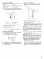
Freestanding Ranges:
1. Measure the distance of the countertop to the floor.
2. Then measure from the top of the range cooktop trim to the
floor.
Tip Over Hazard
A child or adult can tip the range and be killed.
Install anti-tip bracket to floor or wall per installation
instructions.
Slide range back so rear range foot is engaged in the
slot of the anti-tip bracket.
Re-engage anti-tip bracket if range is moved.
Do not operate range without anti-tip bracket installed
and engaged.
Failure to follow these instructions can result in death
or serious burns to children and adults.
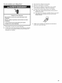
3.
1=
A
A. Distance from the topof the range cooktop trimto the floor
Your leveling height will be the difference between the
2 measurements you have just taken.
If range height adjustment is necessary, use a wrench or
pliers to loosen the 4 leveling legs.
This may be done with the range on its back or with the range
supported on 2 legs after the range has been placed back to
a standing position.
NOTE: To place range back up into astanding position, put a
sheet of cardboard or hardboard in front of range. Using 2 or
more people, stand range back up onto the cardboard or
hardboard.
2. Adjust the leveling legs to the correct height. Leveling legs
can be loosened to add up to a maximum of 1" (2.5 cm). A
minimum of 3/le"(5 mm) is needed to engage the anti-tip
bracket.
NOTE: If height adjustment is made when range is standing,
tilt the range back to adjust the front legs, then tilt forward to
adjust the rear legs.
3. When the range is at the correct height, check that there is
adequate clearance under the range for the anti-tip bracket.
Before sliding range into its final location, check that the anti-
tip bracket will slide under the range and onto the rear
leveling leg prior to anti-tip bracket installation.
1. Remove the anti-tip bracket from where it is taped inside the
storage drawer or warming drawer.
2. Determine which mounting method to use: floor or wall.
If you have a stone or masonry floor, you can use the wall
mounting method. If you are installing the range in a mobile
home, you must secure the range to the floor.
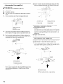
3. Determine and mark the centerline of the cutout space. The
mounting can be installed on either the left side or right side
of the cutout. Position the mounting bracket against the wall
in the cutout so that the V-notch in the bracket is
1313/64"(33.62 cm) from the centerline as shown.
/
A. 1313/_,,(33.62 cm)
B. Bracket V-notch

4. Drill two %" (3 mm) holes that correspond to the bracket
holes of the determined mounting method. See the following
illustrations.
Floor Mounting
Rear position Front position Diagonal (2 options) 8.
Wall Mounting
5. Using a Phillips screwdriver, mount the anti-tip bracket to the
wall or floor with two #12 x 1%" screws provided.
6. Move the range close enough to the opening to allow for final
gas and electrical connections. Remove the shipping base,
cardboard or hardboard from under the range.
7. Move the range into its final location, making sure the rear
leveling leg slides into the anti-tip bracket.
Move the range forward onto shipping base, cardboard or
hardboard to continue installing the range using the following
installation instructions.
-LLS,A,, ()
Power Supply Cord
Electrical Shock Hazard
Disconnect power before servicing.
Use a new 40 amp power supply cord.
Plug into a grounded outlet.
Failure to folow these instructions can result in death,
fire, or electrical shock.
Direct Wire
Electrical Shock Hazard
Disconnect power before servicing.
Use 8 gauge copper or 6 gauge aluminum wire.
Electricaly ground range.
Failure to folow these instructions can result in death,
fire, or electrical shock.
1.
2.
Disconnect power.
Remove the terminal block cover screws located on the back
of the range. Pull cover down and toward you to remove
cover.
3.
Remove plastic tag holding three 10-32 hex nuts from the
middle post of the terminal block.
A. Hold-down screws
B. Terminal block cover
4. Add strain relief.
10

Style 1: Power supply cord strain relief
• Remove the knockout at the bottom of the terminal box
for the 40-amp supply cord.
• Assemble a UL listed strain relief in the opening.
Feed the flexible conduit behind the black horizontal
cross brace and through the strain relief, allowing enough
slack to easily attach the wiring to the terminal block.
A
A. UL fisted strain relief
Feed the power supply cord behind the black horizontal
cross brace and through the strain relief, allowing enough
slack to easily attach the wiring to the terminal block.
A. Black horizontal cross brace
B. Power supply cord
• Tighten strain relief screw against the power supply cord.
Style 2: Direct wire strain relief
• Remove the knockout as needed for the flexible conduit
connection.
• Assemble a UL listed conduit connector in the opening.
A. Removable retaining nut
B. UL fisted strain relief
A. Black horizontal cross brace
B. Flexible conduit
• Tighten strain relief screw against the flexible conduit.
5. Complete installation following instructions for your type of
electrical connection:
4-wire (recommended)
3-wire (if 4-wire is not available)
Electrical Connection Options
If your home has: And you will be Go to Section:
connecting to:
4-wire receptacle A UL listed,
(NEMA type 14-50R) 250-volt
minimum,
40-amp, range
power supply
cord
4-wire connection:
Power supply cord
4-wire direct A fused
disconnect or
circuit breakerbox
(12.7 crn)
4-wire connection:
Direct wire
3-wire receptacle A UL listed,
(NEMA type 10-50R) 250-volt
minimum,
40-amp, range
power supply
cord
3-wire connection:
Power supply cord
3-wire direct A fused 3-wire connection:
3/8. disconnect or Direct wire
(1.0cn_)_, circuit breaker
box
',_f 3........ "
(7.6 crn)
11

4-wire connection: Power Supply Cord
Use this method for:
• New branch-circuit installations (1996 NEC)
• Mobile homes
• Recreational vehicles
• In an area where local codes prohibit grounding through the
neutral.
1. Cut out and remove part of the metal ground strap (B).
5. Use 3/8"nut driver to connect the neutral (white) wire to the
center terminal block 3ost with one of the 10-32 hex nuts.
B
C
F
A. Metal ground strap
B. Discard
C. Ground-rink screw
2. Use a Phillips screwdriver to remove the ground-link screw
from the back of the range. Save the ground-link screw and
the end of the ground link under the screw.
3. Feed the power supply cord through the strain relief on the
cord/conduit plate on bottom of range. Allow enough slack to
easily attach the wiring to the terminal block.
4=
A ......................
i,--¸_ ,
B
A. Terminal block
B. Ground-link screw
C. UL listed strain relief
D. Power supply cord wires
Use a Phillips screwdriver to connect the green ground wire
from the power supply cord to the range with the ground-link
screw and ground-link section. The ground wire must be
attached first.
A. 10-32 hex nut
B. Ground-rink screw
C. Line 2 (red)
D
D. Green ground wire
E.Neutral (center) wire
F. Line 1 (black)
6. Connect line 2 (red) and line 1 (black) wires to the outer
terminal block posts with 10-32 hex nuts.
7. Securely tighten hex nuts.
NOTE: For power supply cord replacement, use only a power
cord rated at 250 volts minimum, 40 amps or 50 amps that is
marked for use with nominal 13/8'' (3.5 cm) diameter
connection opening, with ring terminals and marked for use
with ranges.
8. Tighten strain relief screws.
9. Replace terminal block access cover.
3-wire connection: Power Supply Cord
Use this method only if local codes permit connecting chassis
ground conductor to neutral wire of power supply cord.
1. Feed the power supply cord through the strain relief on the
cord/conduit plate on bottom of range. Allow enough slack to
easily attach the wiring to the terminal block.
A ....................
Q_ B
I
A. Terminal block
B. Ground-link screw
C. UL listed strain relief
D. Power supply cord wires - large opening
12

2. Use 3/8"nut driver to connect the neutral (white) wire to the
center terminal block post with one of the 10-32 hex nuts.
A
E
B
C
A. 10-32 hex nut
B. Line 2 (red)
C. Ground-link screw
D. Neutral (white) wire
E.Line 1 (black)
3. Connect line 2 (red) and line 1 (black) wires to the outer
terminal block posts with 10-32 hex nuts.
4. Securely tighten hex nuts.
NOTE: For power supply cord replacement, use only a power
cord rated at 250 volts minimum, 40 amps or 50 amps that is
marked for use with nominal 13/8"(3.5 cm) diameter
connection opening, with ring terminals and marked for use
with ranges.
5. Tighten strain relief screws.
6. Replace terminal block access cover.
Direct Wire Installation: Copper or Aluminum Wire
This range may be connected directly to the fuse disconnect or
circuit breaker box. Depending on your electrical supply, make
the required 3-wire or 4-wire connection.
1. Strip outer covering back 3" (7.6 cm) to expose wires. Strip
the insulation back 3/8"(1.0 cm) from the end of each wire.
3/8"
(7.6 crn)
2. Allow enough slack in the wire to easily attach the wiring
terminal block.
3. Complete electrical connection according to your type of
electrical supply (4-wire or 3-wire connection).
4-wire Connection: Direct Wire
Use this method for:
• New branch-circuit installations (1996 NEC)
• Mobile homes
• Recreational vehicles
• In an area where local codes prohibit grounding through the
neutral
1. Cut out and remove part of the metal ground strap (B).
A
B
C
A. Metal ground strap
B. Discard
C. Ground-link screw
2. Use a Phillips screwdriver to remove the ground-link screw
from the back of the range. Save the ground-link screw and
the end of the ground link under the screw.
3. Pull the wires through the strain relief on bottom of range.
Allow enough slack to easily attach wiring to the terminal
block.
L..........
B
,i o
C
A. Terminal block
B. Ground-link screw
C. Cord/conduit plate
D. Bare (green) ground wire
E.Line 2 (red) wire
F. Neutral (white) wire
G. Line 1 (black) wire
13

4=
Attach terminal lugs to line 1 (black), neutral (white), and line 2
(red) wires. Loosen (do not remove) the setscrew on the front
of the terminal lug and insert exposed wire end through
bottom of terminal lugs. Securely tighten setscrew to torque
as shown in the following Bare Wire Torque Specifications
chart.
C
A. Terminal lug
B. Setscrew
C. Line 2 (red) wire
D. Neutral (white) wire
E. Line 1 (black) wire
Bare Wire Torque Specifications
Attaching terminal lugs to the terminal block - 20 Ibs-in. (2.3 N-m)
Wire Awg Torque
8 gauge copper 25 Ibs-in. (2.8 N-m)
6 gauge aluminum 35 Ibs-in. (4.0 N-m)
5. Use a hex or Phillips screwdriver to connect the bare (green)
ground wire to the range with the ground-link screw and
ground-link section. The ground wire must be attached first
and must not contact any other terminal.
6. Use 3/8"nut driver to connect the neutral (white) wire to the
center terminal block post with one of the 10-32 hex nuts.
C
A. 10-32 hex nut
B. Line 2 (red)
C. Bare (green) ground wire
D. Ground-link screw
D
E
E. Neutral (white) wire
F. Line 1 (black)
G. Terminal lug
7. Connect line 2 (red) and line 1 (black) wires to the outer
terminal block posts with 10-32 hex nuts.
8. Securely tighten hex nuts.
9. Replace terminal block access cover.
3-wire connection: Direct Wire
Use this method only if local codes permit connecting ground
conductor to neutral supply wire.
1. Pull the wires through the conduit on cord/conduit plate on
bottom of range. Allow enough slack to easily attach the
wiring to the terminal block.
//
................ii
I //
G
B
C
2=
F
A. Terminal block
B. Ground-link screw
C. Cord/conduit plate
D. Line 2 (red) wire
E. Bare (green) ground wire
F. Line 1 (black) wire
G. Metal ground strap
Attach terminal lugs to line 2 (red), bare (green) ground, and
line 1 (black) wires. Loosen (do not remove) the setscrew on
the front of the terminal lug and insert exposed wire end
through bottom of terminal lugs. Securely tighten setscrew to
torque as shown in the following Bare Wire Torque
Specifications chart.
A
C D
A. Terminal lug
B. Setscrew
C. Line 2 (red) wire
D. Bare (green) ground wire
E. Line 1 (black) wire
14

Bare Wire Torque Specifications
Attaching terminal lugs to the terminal block - 20 Ibs-in. (2.3 N-m)
Wire Awg Torque
8 gauge copper 25 Ibs-in. (2.8 N-m)
6 gauge aluminum 35 Ibs-in. (4.0 N-m)
3. Use 3/8"nut driver to connect the bare (green) ground wire to
the center terminal block post with one of the 10-32 hex nuts.
On models with a warming drawer:
1. Place your foot against the bottom front of the warming
drawer, and grasp the control panel with two hands as
shown.
A
i
B
A. 10-32 hex nut
B. Line 2 (red)
C. Ground-link screw
F
E
C
D
D. Bare (green) ground wire
E.Line 1 (black)
F. Terminal lug
4. Connect line 2 (red) and line 1 (black) wires to the outer
terminal block posts with 10-32 hex nuts.
5. Securely tighten hex nuts.
6. Replace terminal block access cover.
On models with a storage drawer:
1. Remove the storage drawer. To remove the storage drawer:
• Pull drawer straight out to the first stop.
• Lift up the back of the drawer and pull out.
2. Use a flashlight to look underneath the bottom of the range.
3. Visually check that the rear range foot is inserted into the slot
of the anti-tip bracket.
2. Slowly attempt to tilt the range forward.
If you encounter immediate resistance, the range foot is
engaged in the anti-tip bracket.
3. If the rear of the range lifts more than 1/2"(1.3 cm) off the floor
without resistance, stop tilting the range and lower it gently
back to the floor. The range foot is not engaged in the anti-tip
bracket.
IMPORTANT: If there is a snapping or popping sound when lifting
the range, the range may not be fully engaged in the bracket.
Check to see if there are obstructions keeping the range from
sliding to the wall or keeping the range foot from sliding into the
bracket. Verify that the bracket is held securely in place by the
mounting screws.
4. Slide the range forward, and verify that the anti-tip bracket is
securely attached to the floor or wall.
5. Slide range back so the rear range foot is inserted into the
slot of the anti-tip bracket.
IMPORTANT: If the back of the range is more than 2" (5.1 cm)
from the mounting wall, the rear range foot may not engage the
bracket. Slide the range forward and determine if there is an
obstruction between the range and the mounting wall. If you
need assistance or service, refer to the cover or the "Warranty"
section of the User Instructions for contact information.
6. Repeat steps 1 and 2 to ensure that the range foot is
engaged in the anti-tip bracket.
If the rear of the range lifts more than V2"(1.3 cm) off the floor
without resistance, the anti-tip bracket may not be installed
correctly. Do not operate the range without anti-tip bracket
installed and engaged. Please reference the "Assistance or
Service" section of the Use and Care Guide, or the cover or
"Warranty" section of the User Instructions, to contact
service.
15

1.
2.
Place a rack in oven.
Place level on rack and check levelness of range, first side to
side; then front to back.
3. If range is not level, pull range forward until rear leveling leg is
removed from the anti-tip bracket.
Use a wrench or pliers to adjust leveling legs up or down until
the range is level. Push range back into position. Check that
rear leveling leg is engaged in the anti-tip bracket.
NOTE: Range must be level for satisfactory baking
performance.
4. Replace the storage drawer:
• Fit the ends of the drawer rails into the guides in the
cavity.
• Slide the drawer closed.
1. Check that all parts are now installed. If there is an extra part,
go back through the steps to see which step was skipped.
2. Check that you have all of your tools.
3. Dispose of/recycle all packaging materials.
4. Check that the range is level. See the "Level Range" section.
5. Use a mild solution of liquid household cleaner and warm
water to remove waxy residue caused by shipping material.
Dry thoroughly with a soft cloth. For more information, read
the "Range Care" section of the Use and Care Guide.
6. Read the "Range Use" section in the range Use and Care
Guide.
7. Plug in range or reconnect power.
8. Turn on surface burners and oven. See the Use and Care
Guide for specific instruction on range operation.
If range does not operate, check the following:
• Household fuse is intact and tight; or circuit breaker has not
tripped.
• Range is plugged into an outlet.
• Electrical supply is connected.
• See the "Troubleshooting" section in the Use and Care Guide.
When the range has been on for 5 minutes, check for heat. If
range is cold, turn off the range and contact a qualified
technician.
Tip Over Hazard
A child or adult can tip the range and be killed.
Install anti-tip bracket to floor or wall per installation
instructions.
Slide range back so rear range foot is engaged in the
slot of the anti-tip bracket.
Re-engage anti-tip bracket if range is moved.
Do not operate range without anti-tip bracket installed
and engaged.
Failure to follow these instructions can result in death
or serious burns to children and adults.
When moving range, slide range onto cardboard or hardboard to
avoid damaging the floor covering.
If removing the range is necessary for cleaning or maintenance:
For power supply cord-connected ranges:
1. Using two or more people, slide range onto cardboard or
hardboard to perform cleaning or maintenance.
2. Unplug the power supply cord.
3. Perform cleaning or maintenance.
4. Plug in range.
5. Check that anti-tip bracket is installed:
• Look for the anti-tip bracket securely attached to floor or
wall.
• Slide range back so rear range foot is under anti-tip
bracket.
6. Check that range is level.
16

For direct-wired ranges:
Electrical Shock Hazard
Disconnect power before servicing.
Replace all parts and panels before operating.
Failure to do so can result in death or electrical shock.
1. Disconnect power.
2. Using two or more people, slide range onto cardboard or
hardboard to perform cleaning or maintenance.
3. Disconnect wiring (if necessary).
4. Perform cleaning or maintenance.
5.
6.
Reconnect wiring (if necessary). See "Electrical Connection -
U.S.A. Only" section.
Check that anti-tip bracket is installed:
• Look for the anti-tip bracket securely attached to floor or
wall.
• Slide range back so rear range foot is under anti-tip
bracket.
7. Check that range is level and reconnect power.
17

P P ,_
SECURITE DE LA CUISINIERE
Votre securite et celle des autres est tres importante.
Nous donnons de nombreux messages de s_curit_ importants dans ce manuel et sur votre appareil m_nager. Assurez-vous de
toujours lire tousles messages de s_curit_ et de vous y conformer.
Voici le symbole d'alerte de s_curit&
Ce symbole d'alerte de s_curit_ vous signale les dangers potentiels de d_c_s et de blessures graves &vous
et &d'autres.
Tous les messages de s_curit_ suivront le symbole d'alerte de s_curit_ et le mot "DANGER" ou
"AVERTISSEMENT". Ces mots signifient •
Risque possible de d6cbs ou de blessure grave si vous ne
suivez pas imm6diatement les instructions.
Risque possible de d6cbs ou de blessure grave si vous
ne suivez pas les instructions.
Tousles messages de s_curit_ vous diront quel est le danger potentiel et vous disent comment r_duire le risque de blessure et
ce qui peut se produire en cas de non-respect des instructions.
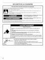
Risque de basculement
Un enfant ou une personne adulte peut faire basculer la cuisiniere, ce qui peut causer un
d6ces.
Fixer la bride antibasculement au plancher ou au mur, conform6ment aux instructions
d'installation.
Faire glisser de nouveau la cuisiniere de fa£on ace que le pied arriere de la cuisiniere se
trouve dans la fente de la bride antibasculement.
R6engager la bride antibasculement si la cuisiniere a 6t6 d6plac6e.
Ne pas faire fonctionner la cuisiniere si la bride antibasculement n'est pas install6e et engag6e.
Le non-respect de ces instructions peut causer un d6cbs ou des brl)lures graves aux enfants et
aux adultes.
Bride
antibasculement
Pied de
la cuisiniere
Pour v6rifier que la bride antibasculement est bien install6e et engag6e :
• Faire glisser la cuisiniere vers ravant.
• V6rifier que la bride antibasculement est bien fix6e au plancher ou au mur.
• Faire de nouveau glisser la cuisiniere vers rarriere de sorte que le pied de la cuisiniere
se trouve sous la bride antibasculement.
• Voir les instructions d'installation pour plus de d6tails.
18

EXIGENCES D'INSTALLATION
Rassembler les outils et piices nicessaires avant de commencer
I'installation. Lire et suivre les instructions fournies avec les outils
indiqu6s ici.
Outillage n_cessaire
• Metre ruban
• Tournevis a lame plate
• Niveau
• Ruban adhesif de masquage
• Tourne-ecrou de 1¼,,
• Tourne-ecrou de 5/le"
• Marteau
• Perceuse manuelle ou
electrique
• Cle ou pince
• Marqueur ou crayon
Foret de 1/8"(3,2 mm) (pour
planchers en bois)
Foret &ma£;onnerie a pointe
carburee de 3/le"(4,8 mm)
[pour planchers en beton/
ceramique]
Pi_ces fournies
Verifierque toutes les pieces sont presentes.
A
Planchette de remplissage arri_re (facultative)
La planchette de remplissage arriere peut etre utilisee pour
combler I'espace entre I'arriere de la cuisiniere encastree et le
mur dans I'ouverture prevue pour une cuisiniere autonome.
A
B
A. Bride anfibasculement
B. Vis n°12 x 1%"
La bride antibasculement doit etre bien fixee au sous-
plancher ou au mur. L'epaisseur du plancher peut necessiter
des vis plus Iongues pour I'ancrage de la bride dans le sous-
plancher. Des vis plus Iongues sont disponibles aupr_s de
votre quincaillerie locale.
Pi6ces n6cessaires
Lors de I'utilisation d'un cordon d'alimentation _lectrique :
• Utiliser un cordon d'alimentation electrique homologue UL
pour utilisation avec les cuisinieres. Utiliser un cordon
250 volts (minimum), 40 ou 50 A, avec marquage pour
utilisation avec une ouverture de raccordement nominal de
13/8"(3,5 cm), et terminaison des conducteurs par cosses
circulaires ou cosses en fourche avec extremites relevees.
• Utiliser egalement un serre-c&ble avec homologation UL.
Consulter les codes Iocaux. Verifier I'alimentation electrique
existante. Voir la section "Specifications electriques".
II est recommande que toutes les connexions electriques soient
effectuees par un electricien qualifie et certifi&
A.Planchette de remplissage arriere
B.Plande travail
C.Ouvertured#coup_e dans le plan de travail
Pour commander, voir la section "Assistance ou service" du
Guide d'utilisation et d'entretien.
Noir - W10113902A
Blanc - W10113903A
Biscuit - W10113904A
IMPORTANT : Observer les dispositions de tousles codes et
r_glements en vigueur.
• C'est &I'installateur qu'incombe la responsabilite de
respecter les distances de separation exigees, specifiees sur
la plaque signaletique de I'appareil. La plaque signaletique
est situee & I'interieur de la porte du four, sur le c6te droit de
la garniture de la porte.
• La cuisiniere doit etre installee &un endroit pratique dans la
cuisine.
• Afin de supprimer le risque de brQlures ou d'incendie en se
penchant au-dessus des unites de surface chauffees, le
rangement en placard au-dessus des unites de surface doit
etre evite. Si le rangement en placard est envisage, le risque
peut etre reduit par I'installation d'une hotte de cuisine ou
d'un ensemble hotte/micro-ondes operant horizontalement
sur un minimum de 5" (12,7 cm) au-del& du bas des placards.
• Respecter les dimensions indiquees pour les ouvertures
decouper dans les placards; ces dimensions constituent les
valeurs minimales des degagements de separation.
• La bride antibasculement doit etre installee. Pour I'installation
de la bride antibasculement fournie avec la cuisiniere, voir la
section "Installation de la bride antibasculement".
• Une source d'electricite avec liaison & la terre est necessaire.
Voir la section "Specifications electriques".
19

IMPORTANT : Pour eviter d'endommager les placards, consulter
le constructeur ou le fabricant du placard pour determiner si les
materiaux utilises ne subiront pas un changement de couleur, une
destratification ou d'autres dommages. Ce four a et6 con£;u
conformement aux exigences UL et aux normes de la CSA
International; il respecte la temperature maximale autorisee pour
les placards en bois : 194°F (90°C).
R_sidence mobile - Specifications additionnelles
respecter Iors de I'installation
L'installation de cette cuisiniere doit _tre conforme aux
dispositions de la norme Manufactured Home Construction and
Safety Standard, Title 24 CFR, Part 3280 (anciennement Federal
Standard for Mobile Home Construction and Safety, Title 24,
HUD Part 280). Lorsque cette norme n'est pas applicable,
I'installation doit satisfaire aux criteres de la norme Standard for
Manufactured Home Installations, ANSI A225.1/NFPA 501A ou
respecter les dispositions des codes Iocaux.
Au Canada, I'installation de cette cuisiniere doit satisfaire aux
stipulations de la version la plus recente de la norme
CAN/CSA-A240 ou des codes Iocaux en vigueur.
Crit_res a respecter pour une installation en r_sidence
mobile :
Dans le cas de I'installation de cette cuisiniere dans une
residence mobile, la cuisiniere doit _tre fixee au plancher
durant tout deplacement du vehicule. Toute methode de
fixation de la cuisiniere est adequate dans la mesure oQelle
satisfait aux criteres des normes mentionnees ci-dessus.
Pour une installation en residence mobile, un c&ble ou cordon
d'alimentation & quatre fils doit _tre utilis& Le c&blage de
I'appareil devra _tre revu. Voir la section "Raccordement
electrique".
Dimensions du produit
Cuisini_re autoportante Cuisini_re coulissante
A
B
E
A. 53A''(14,6 cm)
B. 30" (76,2 cm)
C. 413/4'' (106 cm) : Hauteur totale
avec les pieds de niveflement
completement abaiss#s*
D. 36" (91,4 cm) : Hauteur de la
garniture de la table de cuisson
avec les pieds de niveflement
completement abaiss#s*
E. 30" (76,2 cm)
F. 271/4'' (69,2 cm) : Longueur
maximale de la poign#e au
support a I'arriere de la
cuisiniere**
G. Plaque signal#tique (situ#e
sur la garniture de porte du
four, cSt# droit)
*La cuisin#e peut _tre surelev6e d'environ 1" (2,5 cm) en
ajustant les pieds de nivellement.
**Dans le cas d'une installation entre des placards de
24" (61 cm) avec plan de travail de 25" (63,5 cm), I'avant de la
porte du four sera en saillie de 1" (2,5 cm) au-del& de la base
des placards de 24" (61 cm).
A. 3011_6 '' (77,6 cm)
B. 35%" (90,5 cm) : Hauteur
jusqu 'ala partie inf#rieure du
rebord de la table de cuisson
avec lespieds de nivellement
completement abaiss_s*
C.Plaque signal#tique (situ#esur
la garniture de porte du four,
cSt#droit)
D. 30" (76,2 cm)
E. 27¼" (69,2 cm)
(271_ '' [70,3 cm] sur les
modeles KERS807XSP et
KESS907XSP) : Longueur de
la poign#e au support
I'arriere de la cuisiniere**
F. 23" (58,4 cm) : Longueur de
I'encoche du plan de travail
I'arriere de la table de cuisson
*La cuisiniere peut _tre surelev6e d'environ 1" (2,5 cm) en
ajustant les pieds de nivellement.
**Dans le cas d'une installation entre des placards de
24" (61 cm) avec plan de travail de 25" (63,5 cm), I'avant de la
porte du four sera en saillie de 13A" (4,4 cm) (23Ae'' [5,5 cm] sur
les modeles KERS807XSP et KESS907XSP) au-del& des
placards de 24" (61 cm).
20
La page est en cours de chargement...
La page est en cours de chargement...
La page est en cours de chargement...
La page est en cours de chargement...
La page est en cours de chargement...
La page est en cours de chargement...
La page est en cours de chargement...
La page est en cours de chargement...
-
 1
1
-
 2
2
-
 3
3
-
 4
4
-
 5
5
-
 6
6
-
 7
7
-
 8
8
-
 9
9
-
 10
10
-
 11
11
-
 12
12
-
 13
13
-
 14
14
-
 15
15
-
 16
16
-
 17
17
-
 18
18
-
 19
19
-
 20
20
-
 21
21
-
 22
22
-
 23
23
-
 24
24
-
 25
25
-
 26
26
-
 27
27
-
 28
28


KitchenAid KESK901SSS08 Guide d'installation
- Taper
- Guide d'installation
- Ce manuel convient également à
dans d''autres langues
Documents connexes
Autres documents
-
Whirlpool GY397LXUB Le manuel du propriétaire
-
IKEA GY399LXUQ04 Guide d'installation
-
Jenn-Air JES8850CAS00 Guide d'installation
-
Maytag MET8885XB Installation Instructions Manual
-
Whirlpool W11169656B Manuel utilisateur
-
Amana AER5844VCW0 Guide d'installation
-
IKEA IES505DS0 Guide d'installation
-
Whirlpool KSEB900E Mode d'emploi