La page est en cours de chargement...

1
ID-160
ID-160P
ID-215
ID-215P
ID-320
ID-320P
Package Contents
ID-160(P)/215(P)/320(P) digital signage kiosk Unit.………………....(x1)
Base plate (only for ID-320(P))…...…….…………………………….(x1)
User manual………………………………………………….………..(x1)
#5/16-18 screw nuts (only for ID-320(P))…...….…………………….(x5)
Plan washer (only for ID-320(P))……....……………………………..(x5)
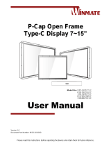
ID-160(P)/215(P)/320(P)
Kiosk
User Manual
18960903020 Ver. B0
http://www.posiflex.com

2
SOME IMPORTANT NOTES
FCC NOTES
This system meets industry & government requirements and applicable standards.
This equipment generates, uses, and can radiate radio frequency energy and, if not
installed and used in accordance with the instructions manual, may cause
interference to radio communications. It has been tested and found to comply with
limits for a Class A digital device pursuant to subpart B of Part 15 of FCC Rules,
which are designed to provide reasonable protection against interference when
operated in a commercial environment. Operation of this equipment in a residential
area is likely to cause interference in which case the user at his own expense will
be required to take whatever measures to correct the interference.
This device complies with part 15 of the FCC Rules. Operation is subject to the
following two conditions: (1) This device may not cause harmful interference, and
(2) this device must accept any interference received, including interference that
may cause undesired operation.
CE CLASS A WARNING
This equipment is compliant with Class A of CISPR 32. In a residential
environment this equipment may cause radio interference.
AVERTISSEMENT CE CLASSE A
Cet équipement est conforme à la classe A de CISPR 32. Dans un environnement
résidentiel, cet équipement peut provoquer des interférences radio.
WARRANTY LIMITS
Warranty will terminate automatically when the machine is opened by any person
other than the authorized technicians. The user should consult his/her dealer for the
problem happening. Warranty voids if the user does not follow the instructions in
application of this merchandise. The manufacturer is by no means responsible for
any damage or hazard caused by improper application.
LIMITES DE GARANTIE
La garantie prend fin automatiquement lorsque la machine est ouverte par une
personne autre que les techniciens autorisés. L'utilisateur doit consulter son
revendeur pour le problème qui se produit. La garantie s'annule si l'utilisateur ne
suit pas les instructions d'application de cette marchandise. Le fabricant n'est en
aucun cas responsable de tout dommage ou danger causé par une mauvaise
application.
警告使用者
這是甲類的資訊產品,在居住的環境中使用時,可能會造成射頻干擾,在這

3
種情況下,使用者會被要求採取某些適當的對策。
SAFETY INSTRUCTIONS
This equipment is not suitable for use in locations where children are likely to be
present.
CONSIGNES DE SÉCURITÉ
Cet équipement ne convient pas à une utilisation dans des lieux pouvant accueillir
des enfants.
BATTERY CAUTION NOTES
Dispose of used batteries according to the instructions.
Replacement of a battery with an incorrect type that can defeat a safeguard
(for example, in the case of some lithium battery types)
Disposal of a battery into fire or a hot oven, or mechanically crushing or
cutting of a battery that can result in an explosion.
Leaving a battery in an extremely high temperature surrounding
environment that can result in an explosion or the leakage of flammable
liquid or gas.
A battery subjected to extremely low air pressure that may result in an
explosion or the leakage of flammable liquid or gas.
BATTERIE ATTENTION NOTES
Jetez les piles usagées conformément aux instructions.
Remplacement d'une batterie avec un type incorrect qui peut annuler une
sauvegarde (par exemple, dans le cas de certains types de batterie au
lithium)
Mise au rebut d'une batterie dans le feu ou dans un four chaud, ou
écrasement ou coupure mécanique d'une batterie pouvant entraîner une
explosion.
Laisser une batterie dans un environnement environnant à des températures
extrêmement élevées pouvant entraîner une explosion ou la fuite de liquide
ou de gaz inflammable.
Une batterie soumise à une pression atmosphérique extrêmement basse
pouvant provoquer une explosion ou une fuite de liquide ou de gaz
inflammable.
警告
本電池如果更換不正確會有爆炸的危險,請依製造商說明書處理用過之電
池。

4
Overview
ID-160(P)
ID-215(P)
15.6”
LCD Panel
I/O Cover Plate
Cable Exit
21.5” LCD
Panel
Cable Exit
I/O Cover
Plate

5
ID-320(P)
View of I/O Interface of ID-160(P)/215(P)/320(P)
32” LCD Panel
Cable Exit
I/O Cover Plate
Base Plate
LAN Port
USB 2.0 Port
USB 3.0 Port
VGA Port
RJ50 COM Port
Audio Port
DC-IN Power Jack

6
Installing the Main Unit on the Base Plate
(Only for ID-320(P))
1. Unscrew the two #6/32-50L hex socket head screws on the rear side of the
kiosk like the below picture. In the same time please make one hand (or
the other person) hold on the front cover from the other side in case the
front cover will fall down.
2. Then gently remove the front cover. Please refer to the pictures.
I/O cover plate

7
3. Place the main unit horizontally on the PE foam and then align the base
plate. Make sure the five screw columns of the base plate are aligning with
the five screw holes of the main unit.

8
4. Put the five washers into the five screw columns.
5. Fix the main unit to the base plate with five #5/16-18 screw nuts.
Connecting Power Adapter and I/O Cables
To have the kiosk ready for operation, please connect the connector of power
adapter and all of the connectors of required I/O cables respectively to the
12VDC-IN power jack and appropriate I/O ports. Please make sure that each
of the cables is fully connected to each of the correct ports. Damages due to
incorrect connection or orientation are not covered by product warranty!
Some cable connectors like the connectors of the COM or LAN cables have to
be gently inserted until a click is heard. It is recommended that the I/O ports,
such as VGA port, should be screwed after the I/O cable connectors are
completely connected. And please make sure that each connector has to be
connected to the right peripheral device in the right way.
CAUTION: On doing insertion or extraction of a cable connector, please
always hold the connector head itself instead of pulling the cable wire.
Doing this could damage the cables and ports, which is considered as an
artificial damage and is not covered by the warranty. The means of power
cord should be connected to a socket-outlet with earthing connection.

9
ATTENTION: Lors de l'insertion ou de l'extraction d'un connecteur de
câble, veuillez toujours tenir la tête du connecteur elle-même au lieu de
tirer le fil du câble. Cela pourrait endommager les câbles, ce qui est
considéré comme un dommage artificiel et n'est pas couvert par la
garantie. Le cordon d'alimentation doit être connecté à une prise de
courant avec mise à la terre.
To connect the I/O cables, you should carefully remove the I/O cover plate.
Please follow the below steps to remove the I/O cover plate.
ID-160(P)
1. Remove the I/O cover plate by unscrewing the lower #6/32-10L hex
socket head screw on the rear side of the kiosk like the picture below.

10
2. Then loosen the upper #6/32-10L hex socket head screw on the rear side
of the kiosk like the picture below, and don’t remove the screw.
3. Lift the I/O cover plate up and then remove the I/O cover plate.

11
ID-215(P)
1. Remove the I/O cover plate by loosening the two #8/32-10L hex socket
head screw on the rear side of the kiosk like the picture below, and don’t
remove the screw.
2. Lift the I/O cover plate up and then remove the I/O cover plate.

12
ID-320(P)
1. Remove the I/O cover plate by unscrewing the two #8/32-10L hex socket
head screws on the rear side of the kiosk like the picture.
2. Loosen the upper two #8/32-10L hex socket head screws like the pictures.
Don’t remove the screws.

13
3. Lift the I/O cover plate up and then remove the I/O cover plate.
Opening the Front Cover (Only for ID-320(P))
1. Unscrew the two #6/32-50L hex socket head screws on the rear side of the
kiosk like the below picture. In the same time please make one hand (or
the other person) hold on the front cover from the other side.
I/O cover plate

14
2. Then gently remove the front cover. Please refer to the pictures.
3. You can drive the power cable, LAN cable, or other cable that you need
down from the LCD monitor to the cable exit at the lower portion of the
kiosk.
You are highly advised not to disassemble or reassemble the kiosk without
professional instructions. Not only might the careless handling during
installation cause irreversible damage to your machine, but also the
improper installation likely leads to system malfunction or failure.
For further installation, please contact the service team of Posiflex for
technical support.
Cable Exit

15
Specifications
ID-160(P)/215(P)/320(P)
System
CPU
Intel Bay Trail J1900 CPU
System Memory
1 x SO-DIMM socket, 8GB DDR3L max.
Storage Device
SATA socket x 1 (2.5” SSD)
OS Support
POSReady 7 64-bit, Windows Embedded 8.1 Industry 64-bit,
Windows 10 IoT 32/64-bit
Touch Screen
ID-160/215/320: N/A (with a glass cover)
ID-160P/215P/320P: P-CAP Touch Screen
LCD Panel
15.6” 1920 x 1080 FHD LCD panel for ID-160
21.5” 1920 x 1080 FHD LCD panel for ID-215
32” 1920 x 1080 FHD LCD panel for ID-320
Power Source
12V/40W power adapter for ID-160(P)
12V/60W power adapter for ID-215(P)
12V/84W power adapter for ID-320(P)
I/O Connectors
Serial Port
2 x RJ50 serial port
Standard USB Port
6 ports, USB 2.0 x 5 + USB 3.0 x 1
LAN Port
1 x 10/100/1000 Mb
Display Port
1 x VGA
Audio
1 x Audio-out + Mic-in combo jack
DC-IN Jack
1 x 12V DC jack (4-pin)
Power Button
1 x power button
Expansion
Expansion Slot
1 x M.2 socket, WiFi 802.11 ac/b/g/n + BT
Physical Dimension
Dimension
(W x D x H in mm)
253 x 261 x 520 for ID-160(P)
543 x 84 x 334 for ID-215(P)
712 x 475 x 1721 for ID-320(P)
Environmental
Operating Condition
0°C - 40°C, 20%RH - 90%RH
Storage Condition
-15°C - 60°C, 10%RH - 90%RH
Optional Item
Wireless COMM
4G LTE dongle, WiFi/BT module
※
The product information and specifications are subject to change without
prior notice. To get the detailed information on the ID-160(P)/215(P)/320(P),
please check this model from Posiflex Global Website, or contact our service
team for technical support.

16
<MEMO>
1/16