
Questions, problems, missing parts? Before returning to your retailer, call our customer
service department at 1-866-994-4148, 8 a.m. - 6 p.m., EST, Monday - Thursday,
8 a.m. - 5 p.m., EST, Friday.
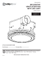
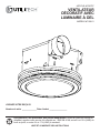
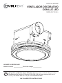
ITEM #0785737
DECORATIVE
VENTILATION FAN
WITH LED LIGHT
MODEL #7109-01
Français p. 12
Español p. 24
ATTACH YOUR RECEIPT HERE
Serial Number
_______________
Purchase Date
______________
TM
AB1739
READ AND SAVE THESE INSTRUCTIONS

2
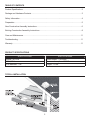
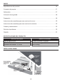
TABLE OF CONTENTS
PRODUCT SPECIFICATIONS
SPECIFICATIONS SPECIFICATIONS
Airow - 80 CFM Sound output - 2.0 Sones
120 V, 60 Hz Power consumption - 27.6 W
Duct diameter - 4 in. Weight - 13 lbs.
Product Specications ........................................................................................................................2
Package and Hardware Contents.......................................................................................................3
Safety Information ..............................................................................................................................4
Preparation .........................................................................................................................................5
New Construction Assembly Instructions ...........................................................................................6
Existing Construction Assembly Instructions ...................................................................................... 8
Care and Maintenance ..................................................................................................................... 11
Troubleshooting ................................................................................................................................ 11
Warranty ........................................................................................................................................... 11
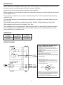
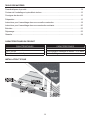
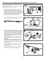
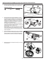
TYPICAL INSTALLATION

3
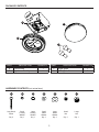
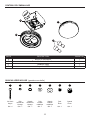
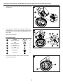
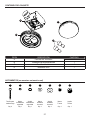
PACKAGE CONTENTS
PART DESCRIPTION QUANTITY PART DESCRIPTION QUANTITY
A Fan housing 1 C Glass globe 1
B Light/rim assembly 1 D LED light bulbs 2
HARDWARE CONTENTS (not actual size)
B
A
C
D
AA BB CC DD EE FF GG
Long Wood
Screw
Small
Locking
Washer
Large
Locking
Washer
Small
Metal
Washer
Large
Metal
Washer
Small
Nut
Large
Nut
Qty. 4 Qty. 1 Qty. 1 Qty. 1 Qty. 1 Qty. 1 Qty. 1

4
SAFETY INFORMATION
READ AND SAVE THESE INSTRUCTIONS
Please read and understand this entire manual before attempting to assemble, operate or install
the product.
1. Always disconnect the power supply prior to servicing the fan, motor or junction box.
2. Installation work must be carried out by a qualied person(s) in accordance to all local and
safety codes including the rules for re-rated construction.
3. Follow all local building, safety and electrical codes, as well as NEC (National Electrical Code)
and OSHA (Occupational Safety and Health Act).
4. Electric service supply must be 120 volts, 60Hz.
5. This unit must be properly grounded.
6. Do not bend or kink the power wires.
7. Exercise care to not damage existing wiring when cutting or drilling into walls or ceilings.
8. Sufcient air supply is required for proper combustion and the exhaustion of gases through
the chimney (ue) of fuel burning equipment to prevent back-drafting. See the standards of
NFPA (National Fire Protection Association) and ASHRAE (American Society for Heating
Refrigeration and Air Conditioning Engineers) and the local building code authorities.
9. Do not use this fan with any solid state control device. Such as a remote control, dimmer switch,
or certain timers. Mechanical timers are not solid state devices.
10. This ventilation fan is approved for use over a bathtub or shower when installed in a GFCI
protected circuit. Do not use fans over a bathtub or shower that are not approved for that
application and marked accordingly.
11. Do not install in a cooking area.
12. Do not use to exhaust hazardous or explosive vapors.
13. Fans should always be vented to the exterior and in compliance with local codes.
14. Do not install in a ceiling with insulation greater than R40.
15. Duct work should be installed in a straight line with minimal bends.
16. Duct work size must be the same size as the discharge and should not be reduced. Reducing
the duct size, may increase fan noise.
17. Prior to servicing or cleaning this unit, shut off power supply at the panel and lock to
prevent the power from being turned on. If the panel cannot be locked, clearly mark
the panel with a warning tag to prevent the power from being turned on.
18. Use this unit in the manner intended by the manufacturer. If you have any questions, please
call the manufacturer (customer service number located on rst page).
19. The fan is intended to be mounted at least 7 ft. (2.1 m) above the oor.
PREPARATION
WARNING: Turn off electricity at breaker box before beginning installation.
Carefully remove unit from carton.
Before beginning assembly of product, make sure all parts are present. Compare parts with package
contents list and hardware contents. If any part is missing or damaged, do not attempt to assemble
the product.

5
PREPARATION
Check area above installation location to be sure that wiring can run to the planned location and that
duct work can be run and the area is sufcient for proper ventilation.
Inspect duct work and wiring before proceeding with installation.
Before installation, provide inspection and future maintenance access at a location that will not interfere
with installation work.
Do not attempt to install this fan in a wall or vaulted ceiling. This fan is for standard horizontal ceiling
installation only.
You may need the help of a second person to install this fan: one person on the attic side and one on
the room side.
Tools required for assembly (not included): Electric Drill, Drill Bits, Phillips Screwdriver, Utility Knife
Other supplies you will need (not included): Duct Tape
Note: Installations may vary depending on how the previous bath fan was installed. Supplies necessary
for the installation of your bath fan are not all included; however, most are available at your local
home improvement or hardware store.
DIMENSIONS
Ceiling
Opening (L)
Ceiling
Opening (W)
Ceiling
Opening (H)
8-1/2 in. 8-5/16 in. 6-11/16 in.
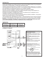
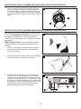
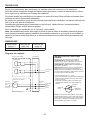
WIRING DIAGRAM
QUICK CONNECTOR INSTRUCTIONS
To be sold only with installation instructions.
WARNING: Wiring must comply with all appliable
electrical codes. Turn OFF power before removing or
installing connectors.
WARNING: COPPER TO COPPER ONLY. Do not use
aluminum wire.
CAUTION: Accessory part (quick connector) should
meet installation instructions below.
NOTE: The connector is reusable on solid wires of the
same wire gage or smaller. Do not reuse the connector
on stranded wires.
• Strip wires 3/8 in. - 1/2 in.
• Grip the wire firmly and push the stripped end of the
wire into the open port of the connector. Use only one
conductor per port.
• Verify the stripped end of the wires is fully inserted to
the back of the connector.
Quick
connect
House
wires
Product
wires
NOTE: Important wire information. Maximum temperature
rating 221˚F (105˚C). 600 volts maximum for building wire
and 1,000 volts maximum for building wire and 1,000 volts
maximum in signs and lighting xtures.
The acceptable wire range includes: Solid: 12-18 AWG.

6
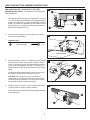
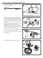
NEW CONSTRUCTION ASSEMBLY INSTRUCTIONS
NEW CONSTRUCTION – ATTACHING TO THE JOIST
BEFORE INSTALLATION – Turn off power source. Review all
safety precautions.
1. Place the fan housing (A) next to a ceiling joist or wall stud
(1.1). The fan housing (A) should be level and perpendicular
to the joist or wall stud (1.1). Allow for thickness of ceiling
board (1.2) used in your application. DO NOT ush mount to
joist or wall stud (1.1). Bottom of fan housing (A) should be
ush with the ceiling board (1.2).
2. Mount the fan housing (A) to joist using the long wood
screws (AA) on both sides.
Hardware Used
AA
Long wood screw x 4
3. Remove wiring box cover (3.1). Pull the house wires through
the wire box cover hole. Using a quick connector, secure
120 V AC house wiring from the wall switch to the fan as
shown in the wiring diagram on page 5. 14 AWG is the
smallest conductor that should be used for branch-circuit
wiring.
Carefully push the connected wires back into the wiring
box housing. Reattach the wiring box cover (3.1).
CAUTION: If the electrical wires do not match the
colors listed, you must determine what each house wire
represents before connecting. You may need to consult
an electrical contractor to determine safely.
4. Install a circular 4 in. duct (4.1) (not included) and secure
it with duct tape or clamps (neither included).
Finish ceiling work. Ceiling hole should be aligned with edge
of fan housing (A).
Joist
Ceiling board
House
wires
Quick
connector
Product
wires
2
3
4
4.1
A
1 2
4
1.2
1.1
1.2
A
A
AA
3.1

7
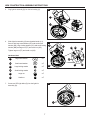
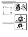
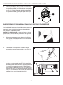
NEW CONSTRUCTION ASSEMBLY INSTRUCTIONS
6
5
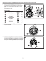
5. Plug light/rim assembly (B) into the fan housing (A).
6. Slide light/rim assembly (B) onto threaded studs (6.1).
Secure with large metal washer (EE) and small metal
washer (DD), large locking washer (CC) and small locking
washer (BB) and large nut (FF) and small nut (GG).
Tighten large nut (FF) and small nut (GG).
Hardware Used
EE
Large metal washer
x 1
DD
Small metal washer
x 1
CC
Large locking washer
x 1
BB
Small locking washer
x 1
FF
Large nut
x 1
GG
Small nut
x 1
7. Screw two LED light bulbs (D) into the light/rim
assembly (B).
GG
A
B
EE
CC
DD
BB
6.1
FF
A
B
7
B
D

8
NEW CONSTRUCTION ASSEMBLY INSTRUCTIONS
8. Place glass globe (C) up to the light/rim assembly (B).
Align the tabs on the light/rim assembly (B) with the indents
on the glass globe (C). Push glass globe into the light/rim
assembly (B) and rotate to lock into place.
8
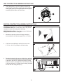
Installing the fan housing in an existing building REQUIRES AN
ACCESSIBLE AREA (attic or crawl space) above the planned
installation location and existing duct and wiring.
BEFORE INSTALLATION – Turn off power source. Review all
safety precautions. Remove existing fan.
1. Measure the opening to ensure it is large enough to
accommodate the new fan housing (8-7/16 in. x 8-1/4 in.).
2. If this fan is not replacing an old fan, be sure to cut a
8-7/16 in. x 8-1/4 in. opening for the fan housing.
3. Place the fan housing (A) next to a ceiling joist or wall stud
(3.1). The fan housing (A) should be level and perpendicular
to the joist or wall stud (3.1). Allow for thickness of ceiling
board (3.2) used in your application. DO NOT ush mount
to joist or wall stud (3.1). Bottom of fan housing (A) should
be ush with the ceiling board (3.2).
1
EXISTING CONSTRUCTION ASSEMBLY INSTRUCTIONS
B
C
2
9.4"
9.4"
8-1/4 in.
8-7/16 in.
1 2
3
3.2
3.1
3.2
A

9
4. Mount the fan housing (A) to joist using the long wood
screws (AA) on both sides.
Hardware Used
AA
Long wood screw
x 4
5. Remove wiring box cover (5.1). Pull the house wires
through the wire box cover hole. Using a quick connector,
secure 120 V AC house wiring from the wall switch to the
fan as shown in the wiring diagram on page 5. 14 AWG
is the smallest conductor that should be used for branch-
circuit wiring.
Carefully push the connected wires back into the wiring
box housing. Reattach the wiring box cover (5.1).
CAUTION: If the electrical wires do not match the
colors listed, you must determine what each house wire
represents before connecting. You may need to consult
an electrical contractor to determine safely.
6. Install a circular 4 in. duct (6.1) (not included) and secure
it with duct tape or clamps (neither included).
Finish ceiling work. Ceiling hole should be aligned with edge
of fan housing (A).
7. Plug light/rim assembly (B) into the fan housing (A).
EXISTING CONSTRUCTION ASSEMBLY INSTRUCTIONS
Joist
Ceiling board
4
A
AA
6
6.1
A
House
wires
Quick
connector
Product
wires
5
5.1
7
A
B

10
8. Slide light/rim assembly (B) onto threaded studs (8.1).
Secure with metal washer (CC), locking washer (BB)
and nut (DD).
Tighten nuts (DD).
Hardware Used
EE
Large metal washer
x 1
DD
Small metal washer
x 1
CC
Large locking washer
x 1
BB
Small locking washer
x 1
FF
Large nut
x 1
GG
Small nut
x 1
9. Screw two LED light bulbs (D) into the light/rim
assembly (B).
10. Place glass globe (C) up to the light/rim assembly (B). Align
the tabs on the light/rim assembly (B) with the indents on
the glass globe (C). Push glass globe (C) into the light/rim
assembly (B) and rotate clockwise to lock into place.
EXISTING CONSTRUCTION ASSEMBLY INSTRUCTIONS
9
GG
A
B
EE
CC
DD
BB
8.1
FF
10
11
B
B
C
D

11
CARE AND MAINTENANCE
WARNING: Disconnect power supply before servicing. See SAFETY INFORMATION before proceeding.
Routine maintenance should be done at least once a year.
• Wash grille with mild soap and water, dry with a cloth.
• Remove excess dirt and dust from the fan housing with a vacuum cleaner.
• Do not use solvents, thinner or harsh chemicals for cleaning the fan.
• Do not allow water to enter the motor.
• Do not immerse resin parts in water over 140º F.
TROUBLESHOOTING
PROBLEM POSSIBLE CAUSE CORRECTIVE ACTION
The fan seems louder
than it should
CFM too great
Be sure the CFM rating on the fan matches
the size of your room
Damper not working properly or damaged
Check damper to ensure it is opening and
closing properly. If the damper has become
damaged, please call Customer Service
Bend in duct too close to fan discharge
Be sure you do not have any sharp bends in
duct closer than 18 in. to the fan discharge
Fan discharge reduced to t smaller duct
Use recommended size ducting to reduce fan
noise
Fan housing not securely attached
Be sure the fan is securely attached
to your ceiling joists
The fan is not
clearing the room
Insufcient intake airow within room
Be sure a door or window is slightly ajar or
opened to allow airow. The fan is not able to
draw air out of the room without enough
airow to draw from
Insufcient CFM
Be sure the CFM rating on the fan matches the
requirements for your room size
NOTE: Using a tissue is not an accurate
method for determining if the fan is operating
properly. If the fan clears steam from the room
within approximately 15 minutes of completing
your shower, then the fan is operating properly.
LIMITED 5-YEAR WARRANTY
If this product fails due to a defect in materials or workmanship at any time during the rst FIVE years of ownership, the
manufacturer will replace it free of charge, postage-paid at their option. This warranty does not cover products that have
been abused, altered, damaged, misused, cut or worn. This warranty does not cover use in commercial applications. Use
only manufacturer-supplied genuine warranty repair replacement parts to repair this fan. Use of non-genuine repair parts
will void your warranty. The manufacturer DISCLAIMS all other implied or express warranties including all warranties of
merchantability and/or tness for a particular purpose. As some states do not allow exclusions or limitations on an implied
warranty, the above exclusions and limitations may not apply. This warranty gives you specic legal rights, and you may
have other rights that vary from state to state.
This warranty is limited to the replacement of defective parts only. Labor charges and/or damage incurred during installation,
repair, replacement as well as incidental and consequential damages connected with the above are excluded. Any damage
to this product as a result of neglect, misuse, accident, imporper installation or use other than the purpose SHALL VOID
THIS WARRANTY.
Shipping costs for return product as part of a claim on the warranty must be paid for by the customer.
Inquiries regarding warranty claims can be directed to 1-866-994-4148, 8 a.m. - 6 p.m., EST, Monday - Thursday,
8 a.m. - 5 p.m., EST, Friday.
Printed in China

Des questions, des problèmes, des pièces manquantes? Avant de retourner l’article au
détaillant, appelez notre service à la clientèle au 1 866 994-4148, entre 8 h et 18 h (HNE) du
lundi au jeudi, ou entre 8 h et 17 h (HNE) le vendredi.
ARTICLE #0785737
VENTILATEUR
DÉCORATIF AVEC
LUMINAIRE À DEL
MODÈLE #7109-01
TM
LISEZ ET CONSERVEZ CES INSTRUCTIONS
JOIGNEZ VOTRE REÇU ICI
Numéro de série _____________ Date d’achat ________________

14
TABLE DES MATIÈRES
CARACTÉRISTIQUES DU PRODUIT
CARACTÉRISTIQUES CARACTÉRISTIQUES
Circulation d’air : 80 pi
3
/min Sortie du son : 2 sones
120 V, 60 Hz Consommation d’énergie du moteur : 27,6 watts
Diamètre du conduit : 4 po Poids : 5,89 kg
Caractéristiques du produit...............................................................................................................14
Contenu de l’emballage et quincaillerie incluse ...............................................................................15
Consignes de sécurité ......................................................................................................................16
Préparation .......................................................................................................................................16
Instructions pour l’assemblage dans une nouvelle construction ......................................................18
Instructions pour l’assemblage dans une construction existante ....................................................20
Entretien ...........................................................................................................................................23
Dépannage .......................................................................................................................................23
Garantie ............................................................................................................................................24
INSTALLATION TYPIQUE

15
CONTENU DE L’EMBALLAGE
PIÈCE DESCRIPTION QUANTITÉ
A Boîtier du ventilateur 1
B Ensemble luminaire/bordure 1
C Globe en verre 1
D Ampoules à DEL 2
QUINCAILLERIE INCLUSE (grandeur non réelle)
B
A
C
D
AA BB CC DD EE FF GG
Vis à bois
longue
Petit
rondelle de
blocage
Grande
rondelle de
blocage
Petit
rondelle
métallique
Grande
rondelle
métallique
Petit
Écrou
Grande
Écrou
Qté : 4 Qté : 1 Qté : 1 Qté : 1 Qté : 1 Qté : 1 Qté : 1

16
CONSIGNES DE SÉCURITÉ
VEUILLEZ LIRE ET CONSERVER CES INSTRUCTIONS.
Assurez-vous de lire et de comprendre l’intégralité du présent manuel avant de tenter d’assembler,
d’installer ou d’utiliser l’article.
1. Fermez toujours l’alimentation électrique avant d’effectuer l’entretien du ventilateur, du moteur ou de
la boîte de jonction.
2. Les travaux d’installation doivent être effectués par une personne qualiée, conformément aux
codes locaux et de sécurité, y compris les règlements relatifs aux installations pare-feu.
3. Respectez tous les codes de construction, de sécurité et d’électricité de votre région, de même
que le Code national de l’électricité et la Loi sur la santé et la sécurité du travail.
4. L’alimentation électrique doit être de 120 V, 60 Hz.
5. Cet appareil doit être mis à la terre de façon appropriée.
6. Ne pliez pas et n’entortillez pas les ls électriques.
7. Veillez à ne pas endommager le câblage existant lors de la découpe ou du forage dans les murs
ou les plafonds.
8. La combustion et l’évacuation complètes, par le conduit de fumée, des gaz des appareils de
combustion requièrent une circulation d’air adéquate pour prévenir les refoulements d’air. Consultez
les normes du Code national de prévention des incendies, de l’American Society for Heating,
Refrigeration and Air Conditioning Engineers (ASHRAE) et du Code national du bâtiment.
9. N’utilisez pas ce ventilateur avec un appareil de réglage à semi-conducteurs, comme une télé-
commande, un gradateur ou certains types de minuteries. Les minuteries mécaniques ne sont pas
des dispositifs de réglage à semi-conducteurs.
10. Ce ventilateur d’aération est approuvé pour une utilisation au-dessus d’une baignoire ou d’une
douche s’il est installé sur un circuit électrique protégé par un disjoncteur différentiel. N’installez
pas ce ventilateur d’aération au-dessus d’une baignoire ou d’une douche s’il ne porte pas une
étiquette d’approbation pour une telle utilisation.
11. N’installez pas l’appareil au-dessus d’une surface de cuisson.
12. Ne l’utilisez pas pour évacuer des vapeurs de matières dangereuses ou explosives.
13. Les ventilateurs doivent toujours évacuer l’air à l’extérieur conformément aux codes locaux.
14. N’installez pas l’appareil dans un plafond dont l’isolation excède R-40.
15. Vous devez installer le conduit en ligne droite, avec un minimum de courbes.
16. La taille du conduit doit être égale à celle de la sortie et ne doit pas être réduite. La réduction de
la taille du conduit peut augmenter le bruit du ventilateur.
17. Avant de procéder à l’entretien ou au nettoyage de cet appareil, vous devez couper l’alimentation
électrique à partir du panneau de distribution et verrouiller celui-ci pour éviter que l’alimentation
ne soit rétablie. Si vous ne pouvez pas verrouiller le tableau de distribution, indiquez clairement,
à l’aide d’une étiquette d’avertissement, de ne pas rétablir l’alimentation.
18. N’utilisez cet appareil que de la façon prévue par le fabricant. Si vous avez des questions, veuillez
communiquer avec le fabricant (le numéro de téléphone du service à la clientèle est à la première
page).
19. Le ventilateur doit être installé à une distance d’au moins 2,13 m (7 pi) du sol.
PRÉPARATION
AVERTISSEMENT : Éteignez l'alimentation électrique du disjoncteur avant de commencer
l'installation.
Retirez soigneusement l’appareil de la boîte.
Avant de commencer l’assemblage du produit, assurez-vous d’avoir toutes les pièces. Comparez le

17
PRÉPARATION
contenu de l’emballage avec la liste des pièces et celle de la quincaillerie incluse. S’il y a des pièces
manquantes ou endommagées, ne tentez pas d’assembler l’article.
Inspectez l’emplacement au-dessus de l’endroit où vous désirez installer l’appareil pour vous assurer
que le câblage peut se rendre à l’endroit prévu, qu’il est possible d’installer un système de conduits et
que l’emplacement est sufsamment grand pour une ventilation adéquate.
Avant de commencer l’installation, inspectez le système de conduits et le câblage.
Avant de commencer l’installation, prévoyez un espace permettant l’accès pour les inspections et
entretiens futurs qui ne sera pas gêné par l’installation.
N’essayez pas d’installer ce ventilateur dans un mur ou un plafond voûté. Ce ventilateur est pour
l’installation de plafond horizontal standard seulement.
Il se peut que vous ayez besoin de l’aide d’une autre personne pour installer le ventilateur : une personne
devrait se trouver dans le grenier, et l’autre dans la pièce.
Outils nécessaires pour l’assemblage (non inclus) : perceuse électrique, forets, tournevis cruciforme
et couteau à lame rétractable. Autre matériel dont vous aurez besoin (non inclus) : ruban à conduits
Remarque : Les installations peuvent varier selon la manière dont le ventilateur précédent a été installé.
Tout le matériel nécessaire à l’installation n’est pas inclus avec le ventilateur, mais vous pouvez vous le
procurer chez un détaillant pour rénovation résidentielle ou dans une quincaillerie.
DIMENSIONS
Ouverture dans
le plafond (L)
Ouverture dans
le plafond (I)
Ouverture dans le
plafond (H)
21,59 cm 21,11 cm 16,98 cm
SCHÉMA DE CÂBLAGE
INSTRUCTIONS POUR LE RACCORD À
BRANCHEMENT RAPIDE
Ne doit être vendu qu’avec les instructions pour l’installation.
AVERTISSEMENT : Le câblage doit être conforme
à tous les codes de l’électricité applicables. Coupez
l’alimentation électrique avant de retirer ou d’installer les
raccords.
AVERTISSEMENT : COMBINAISON DE CUIVRE
AVEC CUIVRE SEULEMENT. N’utilisez pas de l en
aluminium.
ATTENTION : L’accessoire (raccord à branche-
ment rapide) doit être conforme aux instructions pour
l’installation ci-dessous.
REMARQUE : Le raccord est réutilisable avec des ls
massifs du même calibre ou d’un calibre inférieur. Ne
réutilisez pas le raccord avec des ls standard.
• Dénudez les ls de 9,52 mm à 12,7 mm..
• Tenez fermement le fil et poussez l’extrémité dénudée
du fil dans l’orifice du raccord. Utilisez seulement un
conducteur par orifice.
• Vérifiez si l’extrémité dénudée des fils est complète-
ment insérée à l’arrière du raccord.
Raccord à branchement
rapide
Fils de
la maison
Fils de l’article
REMARQUE : Information importante pour le raccor-
dement. La cote de température maximale est de 105 °C
(221 °F). Maximum de 600 V pour les ls de bâtiment;
maximum de 1000 V, pour les ls de bâtiment; maximum de
1000 V, pour les panneaux et les luminaires. Le calibre des
ls acceptable est : de 12 à 18 AWG pour le l massif.

18
INSTRUCTIONS POUR L’ASSEMBLAGE DANS UNE NOUVELLE CONSTRUCTION
NOUVELLE CONSTRUCTION – FIXATION AUX SOLIVES
AVANT L’INSTALLATION : coupez l’alimentation électrique.
Consultez toutes les mesures de sécurité.
1. Placez le boîtier du ventilateur (A) près d’une solive de
plafond ou d’un montant de cloison (1.1). Le boîtier du
ventilateur (A) doit être de niveau et perpendiculaire à la
solive ou au montant de cloison (1.1). Veillez à tenir compte
de l’épaisseur du panneau plafond (1.2). Ne le placez PAS
de niveau avec la solive ou le montant de cloison (1.1). La
partie inférieure du boîtier du ventilateur (A) doit être
parfaitement alignée au panneau plafond (1.2).
2. Installez le boîtier de ventilateur (A) à la solive à l’aide des
longues vis à bois (AA) de chaque côté.
Quincaillerie Utilisée
AA
Vis à bois longue x 4
3. Retirez le couvercle de la boîte de câblage (3.1). Passez les
ls de la maison à travers le trou du couvercle de la boîte
de ls. À l’aide d’un raccord à branchement rapide, xez le
câblage de 120 V c.a. de l’interrupteur mural de la maison
au ventilateur tel qu’il est illustré sur le schéma de câblage
à la page 5. Un conducteur de calibre 14 AWG est le plus
petit conducteur pouvant être utilisé pour un câblage sur un
circuit de dérivation.
Repoussez avec précaution les ls raccordés dans la
boîte de câblage. Remettez le couvercle de la boîte de
câblage (3.1).
ATTENTION : Si la couleur des ls électriques diffère
de celle du manuel, vous devez déterminer la nature de
chaque l avant de les raccorder à l’appareil. Pour le faire
en toute sécurité, vous pourriez devoir faire appel à un
électricien qualié.
4. Installez un conduit circulaire de 4 po (4.1) (non inclus)
et xez-le à l’aide de ruban à conduits ou d’un collier de
serrage (non inclus).
Terminez les travaux au plafond. Vous devez aligner le trou
du plafond au rebord du boîtier du ventilateur (A).
Solive
Panneau plafond
Raccord à
branchement
rapide
Fils de
la maison
Fils de l’article
2
3
4
4.1
A
1 2
4
1.2
1.1
1.2
A
A
AA
3.1

19
INSTRUCTIONS POUR L’ASSEMBLAGE DANS UNE NOUVELLE CONSTRUCTION
5
5. Branchez l’ensemble luminaire/bordure (B) dans le boîtier du
ventilateur (A).
6. Faites glisser l’ensemble luminaire/bordure (B) sur les
goujons letés (6.1). Fixez le tout à l’aide d’une rondelle
de métal (CC), d’une rondelle de blocage (BB) et d’un
écrou (DD).
Serrez les écrous (DD).
Quincaillerie Utilisée
EE
Grande
rondelle métallique
x 1
DD
Petit
rondelle métallique
x 1
CC
Grande
rondelle de blocage
x 1
BB
Petit
rondelle de blocage
x 1
FF
Grande écrou
x 1
GG
Petit écrou
x 1
7. Vissez deux ampoules à DEL (D) dans l’ensemble
luminaire/bordure (B).
A
B
6
GG
A
B
EE
CC
DD
BB
6.1
FF
7
B
D

20
INSTRUCTIONS POUR L’ASSEMBLAGE DANS UNE NOUVELLE CONSTRUCTION
8. Placez le globe en verre (C) sur l’ensemble luminaire/
bordure (B). Alignez les languettes de l’ensemble lumi-
naire/bordure (B) aux marques se trouvant sur le globe
en verre (C). Poussez le globe en verre dans l’ensemble
luminaire/bordure (B) et faites-le pivoter an de le xer en
place.
8
Pour installer le boîtier du ventilateur dans un bâtiment déjà
construit, VOUS DEVEZ AVOIR ACCÈS, par le grenier ou le
faux-plafond, à l’emplacement se trouvant au-dessus de
l’endroit prévu pour l’installation et aux conduits et au câblage
déjà installés.
AVANT L’INSTALLATION : coupez l’alimentation électrique.
Consultez toutes les mesures de sécurité. Retirez le vieux
ventilateur.
1. Mesurez l’ouverture pour vous assurer qu’elle est assez
grande pour accueillir le boîtier du nouveau ventilateur
(21,43 cm x 20,95 cm).
2. S’il s’agit d’un premier ventilateur, taillez une ouverture de
20,43 cm x 20,95 cm pour le boîtier du ventilateur.
3. Placez le boîtier du ventilateur (A) près d’une solive de
plafond ou d’un montant de cloison (3.1). Le boîtier du
ventilateur (A) doit être de niveau et perpendiculaire à la
solive ou au montant de cloison (3.1). Veillez à tenir compte
de l’épaisseur du panneau plafond (3.2). Ne le placez PAS
de niveau avec la solive ou le montant de cloison (3.1). La
partie inférieure du boîtier du ventilateur (A) doit être
parfaitement alignée au panneau plafond (3.2).
1
INSTRUCTIONS POUR L’ASSEMBLAGE DANS UNE CONSTRUCTION EXISTANTE
B
C
2
9.4"
9.4"
20,43 cm
20,95 cm
1 2
3
3.2
3.1
3.2
A

21
4. Installez le boîtier de ventilateur (A) à la solive à l’aide des
longues vis à bois (AA) de chaque côté.
Quincaillerie Utilisée
AA
Vis à bois longue x 4
5. Retirez le couvercle de la boîte de câblage (5.1). Passez les
ls de la maison à travers le trou du couvercle de la boîte
de ls. À l’aide d’un raccord à branchement rapide, xez le
câblage de 120 V c.a. de l’interrupteur mural de la maison
au ventilateur tel qu’il est illustré sur le schéma de câblage
à la page 5. Un conducteur de calibre 14 AWG est le plus
petit conducteur pouvant être utilisé pour un câblage sur un
circuit de dérivation.
Repoussez avec précaution les ls raccordés dans la
boîte de câblage. Remettez le couvercle de la boîte de
câblage (5.1).
ATTENTION : Si la couleur des ls électriques diffère
de celle du manuel, vous devez déterminer la nature de
chaque l avant de les raccorder à l’appareil. Pour le faire
en toute sécurité, vous pourriez devoir faire appel à un
électricien qualié.
6. Installez un conduit circulaire de 4 po (6.1) (non inclus) et
xez-le à l’aide de ruban à conduits ou d’un collier de
serrage (non inclus).
Terminez les travaux au plafond. Vous devez aligner le trou
du plafond au rebord du boîtier du ventilateur (A).
7. Branchez l’ensemble luminaire/bordure (B) dans le boîtier du
ventilateur (A).
INSTRUCTIONS POUR L’ASSEMBLAGE DANS UNE CONSTRUCTION EXISTANTE
6
6.1
A
Solive
Panneau plafond
Raccord à
branchement
rapide
Fils de
la maison
Fils de l’article
4
5
A
AA
5.1
7
A
B
La page est en cours de chargement...
La page est en cours de chargement...
La page est en cours de chargement...
La page est en cours de chargement...
La page est en cours de chargement...
La page est en cours de chargement...
La page est en cours de chargement...
La page est en cours de chargement...
La page est en cours de chargement...
La page est en cours de chargement...
La page est en cours de chargement...
La page est en cours de chargement...
La page est en cours de chargement...
-
 1
1
-
 2
2
-
 3
3
-
 4
4
-
 5
5
-
 6
6
-
 7
7
-
 8
8
-
 9
9
-
 10
10
-
 11
11
-
 12
12
-
 13
13
-
 14
14
-
 15
15
-
 16
16
-
 17
17
-
 18
18
-
 19
19
-
 20
20
-
 21
21
-
 22
22
-
 23
23
-
 24
24
-
 25
25
-
 26
26
-
 27
27
-
 28
28
-
 29
29
-
 30
30
-
 31
31
-
 32
32
-
 33
33


dans d''autres langues
- English: Utilitech 7109-01 Installation guide
- español: Utilitech 7109-01 Guía de instalación
Documents connexes


Autres documents
-
Broan 761BN Instructions Manual
-
Air King AK965L Mode d'emploi
-
 Utilitech Pro SFSDE-500B-A Guide d'installation
-
 Harbor Breeze 40372 Guide d'installation
-
 BV BV-BF-01 Mode d'emploi
-
Sioux Chief 552-C33 Guide d'installation
-
TAYMAC Outdoor Recessed Wall Outlet Enclosure Guide d'installation
-


